(Optional) Software Engineering Case Study: Collaboration Among Objects in the ATM System
(Optional) Software Engineering Case Study Collaboration Among Objects in the ATM System
In this section, we concentrate on the collaborations (interactions) among objects in our ATM system. When two objects communicate with each other to accomplish a task, they are said to collaboratethey do this by invoking one another's operations. A collaboration consists of an object of one class sending a message to an object of another class. Messages are sent in C++ via member-function calls.
In Section 6.18, we determined many of the operations of the classes in our system. In this section, we concentrate on the messages that invoke these operations. To identify the collaborations in the system, we return to the requirements document in Section 2.8. Recall that this document specifies the range of activities that occur during an ATM session (e.g., authenticating a user, performing transactions). The steps used to describe how the system must perform each of these tasks are our first indication of the collaborations in our system. As we proceed through this and the remaining "Software Engineering Case Study" sections, we may discover additional collaborations.
Identifying the Collaborations in a System
We identify the collaborations in the system by carefully reading the sections of the requirements document that specify what the ATM should do to authenticate a user and to perform each transaction type. For each action or step described in the requirements document, we decide which objects in our system must interact to achieve the desired result. We identify one object as the sending object (i.e., the object that sends the message) and another as the receiving object (i.e., the object that offers that operation to clients of the class). We then select one of the receiving object's operations (identified in Section 6.18) that must be invoked by the sending object to produce the proper behavior. For example, the ATM displays a welcome message when idle. We know that an object of class Screen displays a message to the user via its displayMessage operation. Thus, we decide that the system can display a welcome message by employing a collaboration between the ATM and the Screen in which the ATM sends a displayMessage message to the Screen by invoking the displayMessage operation of class Screen. [Note: To avoid repeating the phrase "an object of class...," we refer to each object simply by using its class name preceded by an article ("a," "an" or "the")for example, "the ATM" refers to an object of class ATM.]
Figure 7.27 lists the collaborations that can be derived from the requirements document. For each sending object, we list the collaborations in the order in which they are discussed in the requirements document. We list each collaboration involving a unique sender, message and recipient only once, even though the collaboration may occur several times during an ATM session. For example, the first row in Fig. 7.27 indicates that the ATM collaborates with the Screen whenever the ATM needs to display a message to the user.
|
An object of class... |
sends the message... |
to an object of class... |
|---|---|---|
|
ATM |
|
|
|
BalanceInquiry |
|
|
|
Withdrawal |
|
|
|
Deposit |
|
|
|
BankDatabase |
|
|
Let's consider the collaborations in Fig. 7.27. Before allowing a user to perform any transactions, the ATM must prompt the user to enter an account number, then to enter a PIN. It accomplishes each of these tasks by sending a displayMessage message to the Screen. Both of these actions refer to the same collaboration between the ATM and the Screen, which is already listed in Fig. 7.27. The ATM obtains input in response to a prompt by sending a getInput message to the Keypad. Next, the ATM must determine whether the user-specified account number and PIN match those of an account in the database. It does so by sending an authenticateUser message to the BankDatabase. Recall that the BankDatabase cannot authenticate a user directlyonly the user's Account (i.e., the Account that contains the account number specified by the user) can access the user's PIN to authenticate the user. Figure 7.27 therefore lists a collaboration in which the BankDatabase sends a validatePIN message to an Account.
After the user is authenticated, the ATM displays the main menu by sending a series of displayMessage messages to the Screen and obtains input containing a menu selection by sending a getInput message to the Keypad. We have already accounted for these collaborations. After the user chooses a type of transaction to perform, the ATM executes the transaction by sending an execute message to an object of the appropriate transaction class (i.e., a BalanceInquiry, a Withdrawal or a Deposit). For example, if the user chooses to perform a balance inquiry, the ATM sends an execute message to a BalanceInquiry.
Further examination of the requirements document reveals the collaborations involved in executing each transaction type. A BalanceInquiry retrieves the amount of money available in the user's account by sending a getAvailableBalance message to the BankDatabase, which responds by sending a getAvailableBalance message to the user's Account. Similarly, the BalanceInquiry retrieves the amount of money on deposit by sending a getTotalBalance message to the BankDatabase, which sends the same message to the user's Account. To display both measures of the user's balance at the same time, the BalanceInquiry sends a displayMessage message to the Screen.
A Withdrawal sends a series of displayMessage messages to the Screen to display a menu of standard withdrawal amounts (i.e., $20, $40, $60, $100, $200). The Withdrawal sends a getInput message to the Keypad to obtain the user's menu selection. Next, the Withdrawal determines whether the requested withdrawal amount is less than or equal to the user's account balance. The Withdrawal can obtain the amount of money available in the user's account by sending a getAvailableBalance message to the BankDatabase. The Withdrawal then tests whether the cash dispenser contains enough cash by sending an isSufficientCashAvailable message to the CashDispenser. A Withdrawal sends a debit message to the BankDatabase to decrease the user's account balance. The BankDatabase in turn sends the same message to the appropriate Account. Recall that debiting funds from an Account decreases both the totalBalance and the availableBalance. To dispense the requested amount of cash, the Withdrawal sends a dispenseCash message to the CashDispenser. Finally, the Withdrawal sends a displayMessage message to the Screen, instructing the user to take the cash.
A Deposit responds to an execute message first by sending a displayMessage message to the Screen to prompt the user for a deposit amount. The Deposit sends a getInput message to the Keypad to obtain the user's input. The Deposit then sends a displayMessage message to the Screen to tell the user to insert a deposit envelope. To determine whether the deposit slot received an incoming deposit envelope, the Deposit sends an isEnvelopeReceived message to the DepositSlot. The Deposit updates the user's account by sending a credit message to the BankDatabase, which subsequently sends a credit message to the user's Account. Recall that crediting funds to an Account increases the totalBalance but not the availableBalance.
Interaction Diagrams
Now that we have identified a set of possible collaborations between the objects in our ATM system, let us graphically model these interactions using the UML. The UML provides several types of interaction diagrams that model the behavior of a system by modeling how objects interact with one another. The communication diagram emphasizes which objects participate in collaborations. [Note: Communication diagrams were called collaboration diagrams in earlier versions of the UML.] Like the communication diagram, the sequence diagram shows collaborations among objects, but it emphasizes when messages are sent between objects over time.
Communication Diagrams
Figure 7.28 shows a communication diagram that models the ATM executing a BalanceInquiry. Objects are modeled in the UML as rectangles containing names in the form objectName : ClassName. In this example, which involves only one object of each type, we disregard the object name and list only a colon followed by the class name. [Note: Specifying the name of each object in a communication diagram is recommended when modeling multiple objects of the same type.] Communicating objects are connected with solid lines, and messages are passed between objects along these lines in the direction shown by arrows. The name of the message, which appears next to the arrow, is the name of an operation (i.e., a member function) belonging to the receiving objectthink of the name as a service that the receiving object provides to sending objects (its "clients").
Figure 7.28. Communication diagram of the ATM executing a balance inquiry.
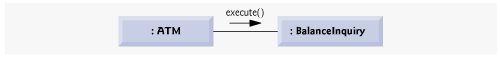
The solid filled arrow in Fig. 7.28 represents a messageor synchronous callin the UML and a function call in C++. This arrow indicates that the flow of control is from the sending object (the ATM) to the receiving object (a BalanceInquiry). Since this is a synchronous call, the sending object may not send another message, or do anything at all, until the receiving object processes the message and returns control to the sending object. The sender just waits. For example, in Fig. 7.28, the ATM calls member function execute of a BalanceInquiry and may not send another message until execute has finished and returns control to the ATM. [Note: If this were an asynchronous call, represented by a stick arrowhead, the sending object would not have to wait for the receiving object to return controlit would continue sending additional messages immediately following the asynchronous call. Asynchronous calls often can be implemented in C++ using platform-specific libraries provided with your compiler. Such techniques are beyond the scope of this book.]
Sequence of Messages in a Communication Diagram
Figure 7.29 shows a communication diagram that models the interactions among objects in the system when an object of class BalanceInquiry executes. We assume that the object's accountNumber attribute contains the account number of the current user. The collaborations in Fig. 7.29 begin after the ATM sends an execute message to a BalanceInquiry (i.e., the interaction modeled in Fig. 7.28). The number to the left of a message name indicates the order in which the message is passed. The sequence of messages in a communication diagram progresses in numerical order from least to greatest. In this diagram, the numbering starts with message 1 and ends with message 3. The BalanceInquiry first sends a getAvailableBalance message to the BankDatabase (message 1), then sends a getTotalBalance message to the BankDatabase (message 2). Within the parentheses following a message name, we can specify a comma-separated list of the names of the parameters sent with the message (i.e., arguments in a C++ function call)the BalanceInquiry passes attribute accountNumber with its messages to the BankDatabase to indicate which Account's balance information to retrieve. Recall from Fig. 6.33 that operations getAvailableBalance and getTotalBalance of class BankDatabase each require a parameter to identify an account. The BalanceInquiry next displays the availableBalance and the totalBalance to the user by passing a displayMessage message to the Screen (message 3) that includes a parameter indicating the message to be displayed.
Figure 7.29. Communication diagram for executing a balance inquiry.
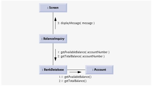
Note, however, that Fig. 7.29 models two additional messages passing from the BankDatabase to an Account (message 1.1 and message 2.1). To provide the ATM with the two balances of the user's Account (as requested by messages 1 and 2), the BankDatabase must pass a getAvailableBalance and a getTotalBalance message to the user's Account. Such messages passed within the handling of another message are called nested messages. The UML recommends using a decimal numbering scheme to indicate nested messages. For example, message 1.1 is the first message nested in message 1the BankDatabase passes a getAvailableBalance message during BankDatabase's processing of a message by the same name. [Note: If the BankDatabase needed to pass a second nested message while processing message 1, the second message would be numbered 1.2.] A message may be passed only when all the nested messages from the previous message have been passed. For example, the BalanceInquiry passes message 3 only after messages 2 and 2.1 have been passed, in that order.
The nested numbering scheme used in communication diagrams helps clarify precisely when and in what context each message is passed. For example, if we numbered the messages in Fig. 7.29 using a flat numbering scheme (i.e., 1, 2, 3, 4, 5), someone looking at the diagram might not be able to determine that BankDatabase passes the getAvailableBalance message (message 1.1) to an Account during the BankDatabase's processing of message 1, as opposed to after completing the processing of message 1. The nested decimal numbers make it clear that the second getAvailableBalance message (message 1.1) is passed to an Account within the handling of the first getAvailableBalance message (message 1) by the BankDatabase.
Sequence Diagrams
Communication diagrams emphasize the participants in collaborations but model their timing a bit awkwardly. A sequence diagram helps model the timing of collaborations more clearly. Figure 7.30 shows a sequence diagram modeling the sequence of interactions that occur when a Withdrawal executes. The dotted line extending down from an object's rectangle is that object's lifeline, which represents the progression of time. Actions typically occur along an object's lifeline in chronological order from top to bottoman action near the top typically happens before one near the bottom.
Figure 7.30. Sequence diagram that models a Withdrawal executing.
(This item is displayed on page 382 in the print version)
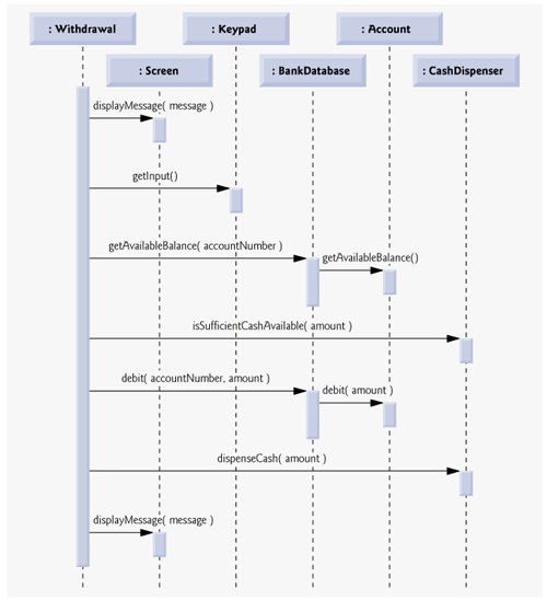
Message passing in sequence diagrams is similar to message passing in communication diagrams. A solid arrow with a filled arrowhead extending from the sending object to the receiving object represents a message between two objects. The arrowhead points to an activation on the receiving object's lifeline. An activation, shown as a thin vertical rectangle, indicates that an object is executing. When an object returns control, a return message, represented as a dashed line with a stick arrowhead, extends from the activation of the object returning control to the activation of the object that initially sent the message. To eliminate clutter, we omit the return-message arrowsthe UML allows this practice to make diagrams more readable. Like communication diagrams, sequence diagrams can indicate message parameters between the parentheses following a message name.
The sequence of messages in Fig. 7.30 begins when a Withdrawal prompts the user to choose a withdrawal amount by sending a displayMessage message to the Screen. The Withdrawal then sends a getInput message to the Keypad, which obtains input from the user. We have already modeled the control logic involved in a Withdrawal in the activity diagram of Fig. 5.28, so we do not show this logic in the sequence diagram of Fig. 7.30. Instead, we model the best-case scenario in which the balance of the user's account is greater than or equal to the chosen withdrawal amount, and the cash dispenser contains a sufficient amount of cash to satisfy the request. For information on how to model control logic in a sequence diagram, please refer to the Web resources and recommended readings listed at the end of Section 2.8.
After obtaining a withdrawal amount, the Withdrawal sends a getAvailableBalance message to the BankDatabase, which in turn sends a getAvailableBalance message to the user's Account. Assuming that the user's account has enough money available to permit the transaction, the Withdrawal next sends an isSufficientCashAvailable message to the CashDispenser. Assuming that there is enough cash available, the Withdrawal decreases the balance of the user's account (i.e., both the totalBalance and the availableBalance) by sending a debit message to the BankDatabase. The BankDatabase responds by sending a debit message to the user's Account. Finally, the Withdrawal sends a dispenseCash message to the CashDispenser and a displayMessage message to the Screen, telling the user to remove the cash from the machine.
We have identified the collaborations among objects in the ATM system and modeled some of these collaborations using UML interaction diagramsboth communication diagrams and sequence diagrams. In the next "Software Engineering Case Study" section (Section 9.12), we enhance the structure of our model to complete a preliminary object-oriented design, then we begin implementing the ATM system.
Software Engineering Case Study Self-Review Exercises
| 7.1 |
A(n) __________ consists of an object of one class sending a message to an object of another class.
|
| 7.2 |
Which form of interaction diagram emphasizes what collaborations occur? Which form emphasizes when collaborations occur? |
|
|
|
| 7.3 |
Create a sequence diagram that models the interactions among objects in the ATM system that occur when a Deposit executes successfully, and explain the sequence of messages modeled by the diagram. |
Answers to Software Engineering Case Study Self-Review Exercises
| 7.1 |
c. |
| 7.2 |
Communication diagrams emphasize what collaborations occur. Sequence diagrams emphasize when collaborations occur. |
| 7.3 |
Figure 7.31 presents a sequence diagram that models the interactions between objects in the ATM system that occur when a Deposit executes successfully. Figure 7.31 indicates that a Deposit first sends a displayMessage message to the Screen to ask the user to enter a deposit amount. Next the Deposit sends a getInput message to the Keypad to receive input from the user. The Deposit then instructs the user to enter a deposit envelope by sending a displayMessage message to the Screen. The Deposit next sends an isEnvelopeReceived message to the DepositSlot to confirm that the deposit envelope has been received by the ATM. Finally, the Deposit increases the totalBalance attribute (but not the availableBalance attribute) of the user's Account by sending a credit message to the BankDatabase. The BankDatabase responds by sending the same message to the user's Account. Figure 7.31. Sequence diagram that models a Deposit executing. 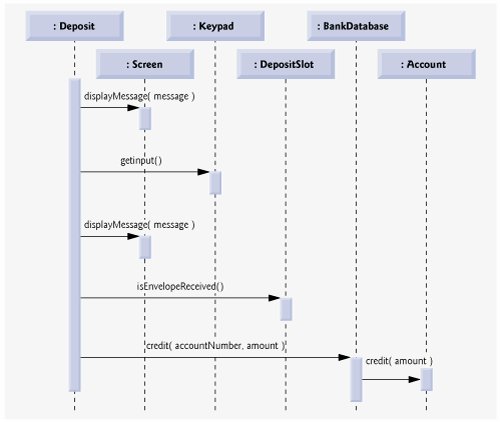
|
Introduction to Computers, the Internet and World Wide Web
- Introduction
- What Is a Computer?
- Computer Organization
- Early Operating Systems
- Personal, Distributed and Client/Server Computing
- The Internet and the World Wide Web
- Machine Languages, Assembly Languages and High-Level Languages
- History of C and C++
- C++ Standard Library
- History of Java
- FORTRAN, COBOL, Pascal and Ada
- Basic, Visual Basic, Visual C++, C# and .NET
- Key Software Trend: Object Technology
- Typical C++ Development Environment
- Notes About C++ and C++ How to Program, 5/e
- Test-Driving a C++ Application
- Software Engineering Case Study: Introduction to Object Technology and the UML (Required)
- Wrap-Up
- Web Resources
- Summary
- Terminology
- Self-Review Exercises
- Exercises
Introduction to C++ Programming
- Introduction
- First Program in C++: Printing a Line of Text
- Modifying Our First C++ Program
- Another C++ Program: Adding Integers
- Memory Concepts
- Arithmetic
- Decision Making: Equality and Relational Operators
- (Optional) Software Engineering Case Study: Examining the ATM Requirements Document
- Wrap-Up
- Summary
- Terminology
- Self-Review Exercises
- Exercises
Introduction to Classes and Objects
- Introduction
- Classes, Objects, Member Functions and Data Members
- Overview of the Chapter Examples
- Defining a Class with a Member Function
- Defining a Member Function with a Parameter
- Data Members, set Functions and get Functions
- Initializing Objects with Constructors
- Placing a Class in a Separate File for Reusability
- Separating Interface from Implementation
- Validating Data with set Functions
- (Optional) Software Engineering Case Study: Identifying the Classes in the ATM Requirements Document
- Wrap-Up
- Summary
- Terminology
- Self-Review Exercises
- Exercises
Control Statements: Part 1
- Introduction
- Algorithms
- Pseudocode
- Control Structures
- if Selection Statement
- if...else Double-Selection Statement
- while Repetition Statement
- Formulating Algorithms: Counter-Controlled Repetition
- Formulating Algorithms: Sentinel-Controlled Repetition
- Formulating Algorithms: Nested Control Statements
- Assignment Operators
- Increment and Decrement Operators
- (Optional) Software Engineering Case Study: Identifying Class Attributes in the ATM System
- Wrap-Up
- Summary
- Terminology
- Self-Review Exercises
- Exercises
Control Statements: Part 2
- Introduction
- Essentials of Counter-Controlled Repetition
- for Repetition Statement
- Examples Using the for Statement
- do...while Repetition Statement
- switch Multiple-Selection Statement
- break and continue Statements
- Logical Operators
- Confusing Equality (==) and Assignment (=) Operators
- Structured Programming Summary
- (Optional) Software Engineering Case Study: Identifying Objects States and Activities in the ATM System
- Wrap-Up
- Summary
- Terminology
- Self-Review Exercises
- Exercises
Functions and an Introduction to Recursion
- Introduction
- Program Components in C++
- Math Library Functions
- Function Definitions with Multiple Parameters
- Function Prototypes and Argument Coercion
- C++ Standard Library Header Files
- Case Study: Random Number Generation
- Case Study: Game of Chance and Introducing enum
- Storage Classes
- Scope Rules
- Function Call Stack and Activation Records
- Functions with Empty Parameter Lists
- Inline Functions
- References and Reference Parameters
- Default Arguments
- Unary Scope Resolution Operator
- Function Overloading
- Function Templates
- Recursion
- Example Using Recursion: Fibonacci Series
- Recursion vs. Iteration
- (Optional) Software Engineering Case Study: Identifying Class Operations in the ATM System
- Wrap-Up
- Summary
- Terminology
- Self-Review Exercises
- Exercises
Arrays and Vectors
- Introduction
- Arrays
- Declaring Arrays
- Examples Using Arrays
- Passing Arrays to Functions
- Case Study: Class GradeBook Using an Array to Store Grades
- Searching Arrays with Linear Search
- Sorting Arrays with Insertion Sort
- Multidimensional Arrays
- Case Study: Class GradeBook Using a Two-Dimensional Array
- Introduction to C++ Standard Library Class Template vector
- (Optional) Software Engineering Case Study: Collaboration Among Objects in the ATM System
- Wrap-Up
- Summary
- Terminology
- Self-Review Exercises
- Exercises
- Recursion Exercises
- vector Exercises
Pointers and Pointer-Based Strings
- Introduction
- Pointer Variable Declarations and Initialization
- Pointer Operators
- Passing Arguments to Functions by Reference with Pointers
- Using const with Pointers
- Selection Sort Using Pass-by-Reference
- sizeof Operators
- Pointer Expressions and Pointer Arithmetic
- Relationship Between Pointers and Arrays
- Arrays of Pointers
- Case Study: Card Shuffling and Dealing Simulation
- Function Pointers
- Introduction to Pointer-Based String Processing
- Wrap-Up
- Summary
- Terminology
- Self-Review Exercises
- Exercises
- Special Section: Building Your Own Computer
- More Pointer Exercises
- String-Manipulation Exercises
- Special Section: Advanced String-Manipulation Exercises
- A Challenging String-Manipulation Project
Classes: A Deeper Look, Part 1
- Introduction
- Time Class Case Study
- Class Scope and Accessing Class Members
- Separating Interface from Implementation
- Access Functions and Utility Functions
- Time Class Case Study: Constructors with Default Arguments
- Destructors
- When Constructors and Destructors Are Called
- Time Class Case Study: A Subtle TrapReturning a Reference to a private Data Member
- Default Memberwise Assignment
- Software Reusability
- (Optional) Software Engineering Case Study: Starting to Program the Classes of the ATM System
- Wrap-Up
- Summary
- Terminology
- Self-Review Exercises
- Exercises
Classes: A Deeper Look, Part 2
- Introduction
- const (Constant) Objects and const Member Functions
- Composition: Objects as Members of Classes
- friend Functions and friend Classes
- Using the this Pointer
- Dynamic Memory Management with Operators new and delete
- static Class Members
- Data Abstraction and Information Hiding
- Container Classes and Iterators
- Proxy Classes
- Wrap-Up
- Summary
- Terminology
- Self-Review Exercises
- Exercises
Operator Overloading; String and Array Objects
- Introduction
- Fundamentals of Operator Overloading
- Restrictions on Operator Overloading
- Operator Functions as Class Members vs. Global Functions
- Overloading Stream Insertion and Stream Extraction Operators
- Overloading Unary Operators
- Overloading Binary Operators
- Case Study: Array Class
- Converting between Types
- Case Study: String Class
- Overloading ++ and --
- Case Study: A Date Class
- Standard Library Class string
- explicit Constructors
- Wrap-Up
- Summary
- Terminology
- Self-Review Exercises
- Exercises
Object-Oriented Programming: Inheritance
- Introduction
- Base Classes and Derived Classes
- protected Members
- Relationship between Base Classes and Derived Classes
- Constructors and Destructors in Derived Classes
- public, protected and private Inheritance
- Software Engineering with Inheritance
- Wrap-Up
- Summary
- Terminology
- Self-Review Exercises
- Exercises
Object-Oriented Programming: Polymorphism
- Introduction
- Polymorphism Examples
- Relationships Among Objects in an Inheritance Hierarchy
- Type Fields and switch Statements
- Abstract Classes and Pure virtual Functions
- Case Study: Payroll System Using Polymorphism
- (Optional) Polymorphism, Virtual Functions and Dynamic Binding Under the Hood
- Case Study: Payroll System Using Polymorphism and Run-Time Type Information with Downcasting, dynamic_cast, typeid and type_info
- Virtual Destructors
- (Optional) Software Engineering Case Study: Incorporating Inheritance into the ATM System
- Wrap-Up
- Summary
- Terminology
- Self-Review Exercises
- Exercises
Templates
- Introduction
- Function Templates
- Overloading Function Templates
- Class Templates
- Nontype Parameters and Default Types for Class Templates
- Notes on Templates and Inheritance
- Notes on Templates and Friends
- Notes on Templates and static Members
- Wrap-Up
- Summary
- Terminology
- Self-Review Exercises
- Exercises
Stream Input/Output
- Introduction
- Streams
- Stream Output
- Stream Input
- Unformatted I/O using read, write and gcount
- Introduction to Stream Manipulators
- Stream Format States and Stream Manipulators
- Stream Error States
- Tying an Output Stream to an Input Stream
- Wrap-Up
- Summary
- Terminology
- Self-Review Exercises
- Exercises
Exception Handling
- Introduction
- Exception-Handling Overview
- Example: Handling an Attempt to Divide by Zero
- When to Use Exception Handling
- Rethrowing an Exception
- Exception Specifications
- Processing Unexpected Exceptions
- Stack Unwinding
- Constructors, Destructors and Exception Handling
- Exceptions and Inheritance
- Processing new Failures
- Class auto_ptr and Dynamic Memory Allocation
- Standard Library Exception Hierarchy
- Other Error-Handling Techniques
- Wrap-Up
- Summary
- Terminology
- Self-Review Exercises
- Exercises
File Processing
- Introduction
- The Data Hierarchy
- Files and Streams
- Creating a Sequential File
- Reading Data from a Sequential File
- Updating Sequential Files
- Random-Access Files
- Creating a Random-Access File
- Writing Data Randomly to a Random-Access File
- Reading from a Random-Access File Sequentially
- Case Study: A Transaction-Processing Program
- Input/Output of Objects
- Wrap-Up
- Summary
- Terminology
- Self-Review Exercises
- Exercises
Class string and String Stream Processing
- Introduction
- string Assignment and Concatenation
- Comparing strings
- Substrings
- Swapping strings
- string Characteristics
- Finding Strings and Characters in a string
- Replacing Characters in a string
- Inserting Characters into a string
- Conversion to C-Style Pointer-Based char * Strings
- Iterators
- String Stream Processing
- Wrap-Up
- Summary
- Terminology
- Self-Review Exercises
- Exercises
Web Programming
- Introduction
- HTTP Request Types
- Multitier Architecture
- Accessing Web Servers
- Apache HTTP Server
- Requesting XHTML Documents
- Introduction to CGI
- Simple HTTP Transactions
- Simple CGI Scripts
- Sending Input to a CGI Script
- Using XHTML Forms to Send Input
- Other Headers
- Case Study: An Interactive Web Page
- Cookies
- Server-Side Files
- Case Study: Shopping Cart
- Wrap-Up
- Internet and Web Resources
- Summary
- Terminology
- Self-Review Exercises
- Exercises
Searching and Sorting
- Introduction
- Searching Algorithms
- Sorting Algorithms
- Wrap-Up
- Summary
- Terminology
- Self-Review Exercises
- Exercises
Data Structures
- Introduction
- Self-Referential Classes
- Dynamic Memory Allocation and Data Structures
- Linked Lists
- Stacks
- Queues
- Trees
- Wrap-Up
- Summary
- Terminology
- Self-Review Exercises
- Exercises
- Special Section: Building Your Own Compiler
Bits, Characters, C-Strings and structs
- Introduction
- Structure Definitions
- Initializing Structures
- Using Structures with Functions
- typedef
- Example: High-Performance Card Shuffling and Dealing Simulation
- Bitwise Operators
- Bit Fields
- Character-Handling Library
- Pointer-Based String-Conversion Functions
- Search Functions of the Pointer-Based String-Handling Library
- Memory Functions of the Pointer-Based String-Handling Library
- Wrap-Up
- Summary
- Terminology
- Self-Review Exercises
- Exercises
Standard Template Library (STL)
- Introduction to the Standard Template Library (STL)
- Sequence Containers
- Associative Containers
- Container Adapters
- Algorithms
- Class bitset
- Function Objects
- Wrap-Up
- STL Internet and Web Resources
- Summary
- Terminology
- Self-Review Exercises
- Exercises
- Recommended Reading
Other Topics
- Introduction
- const_cast Operator
- namespaces
- Operator Keywords
- mutable Class Members
- Pointers to Class Members (.* and ->*)
- Multiple Inheritance
- Multiple Inheritance and virtual Base Classes
- Wrap-Up
- Closing Remarks
- Summary
- Terminology
- Self-Review Exercises
- Exercises
Appendix A. Operator Precedence and Associativity Chart
Appendix B. ASCII Character Set
Appendix C. Fundamental Types
Appendix D. Number Systems
- D.1. Introduction
- D.2. Abbreviating Binary Numbers as Octal and Hexadecimal Numbers
- D.3. Converting Octal and Hexadecimal Numbers to Binary Numbers
- D.4. Converting from Binary, Octal or Hexadecimal to Decimal
- D.5. Converting from Decimal to Binary, Octal or Hexadecimal
- D.6. Negative Binary Numbers: Twos Complement Notation
- Summary
- Terminology
- Self-Review Exercises
- Exercises
Appendix E. C Legacy Code Topics
- E.1. Introduction
- E.2. Redirecting Input/Output on UNIX/LINUX/Mac OS X and Windows Systems
- E.3. Variable-Length Argument Lists
- E.4. Using Command-Line Arguments
- E.5. Notes on Compiling Multiple-Source-File Programs
- E.6. Program Termination with exit and atexit
- E.7. The volatile Type Qualifier
- E.8. Suffixes for Integer and Floating-Point Constants
- E.9. Signal Handling
- E.10. Dynamic Memory Allocation with calloc and realloc
- E.11. The Unconditional Branch: goto
- E.12. Unions
- E.13. Linkage Specifications
- E.14. Wrap-Up
- Summary
- Terminology
- Self-Review Exercises
- Exercises
Appendix F. Preprocessor
- F.1. Introduction
- F.2. The #include Preprocessor Directive
- F.3. The #define Preprocessor Directive: Symbolic Constants
- F.4. The #define Preprocessor Directive: Macros
- F.5. Conditional Compilation
- F.6. The #error and #pragma Preprocessor Directives
- F.7. The # and ## Operators
- F.8. Predefined Symbolic Constants
- F.9. Assertions
- F.10. Wrap-Up
- Summary
- Terminology
- Self-Review Exercises
- Exercises
Appendix G. ATM Case Study Code
- Appendix G. ATM Case Study Code
- G.1. ATM Case Study Implementation
- G.2. Class ATM
- G.3. Class Screen
- G.4. Class Keypad
- G.5. Class CashDispenser
- G.6. Class DepositSlot
- G.7. Class Account
- G.8. Class BankDatabase
- G.9. Class Transaction
- G.10. Class BalanceInquiry
- G.11. Class Withdrawal
- G.12. Class Deposit
- G.13. Test Program ATMCaseStudy.cpp
- G.14. Wrap-Up
Appendix H. UML 2: Additional Diagram Types
Appendix I. C++ Internet and Web Resources
- Appendix I. C++ Internet and Web Resources
- I.1. Resources
- I.2. Tutorials
- I.3. FAQs
- I.4. Visual C++
- I.5. Newsgroups
- I.6. Compilers and Development Tools
- I.7. Standard Template Library
Appendix J. Introduction to XHTML
- J.1. Introduction
- J.2. Editing XHTML
- J.3. First XHTML Example
- J.4. Headers
- J.5. Linking
- J.6. Images
- J.7. Special Characters and More Line Breaks
- J.8. Unordered Lists
- J.9. Nested and Ordered Lists
- J.10. Basic XHTML Tables
- J.11. Intermediate XHTML Tables and Formatting
- J.12. Basic XHTML Forms
- J.13. More Complex XHTML Forms
- J.14. Internet and World Wide Web Resources
- Summary
- Terminology
Appendix K. XHTML Special Characters
Appendix L. Using the Visual Studio .NET Debugger
- L.1. Introduction
- L.2. Breakpoints and the Continue Command
- L.3. The Locals and Watch Windows
- L.4. Controlling Execution Using the Step Into, Step Over, Step Out and Continue Commands
- L.5. The Autos Window
- L.6. Wrap-Up
- Summary
- Terminology
- Self-Review Exercises
Appendix M. Using the GNU C++ Debugger
- M.1. Introduction
- M.2. Breakpoints and the run, stop, continue and print Commands
- M.3. The print and set Commands
- M.4. Controlling Execution Using the step, finish and next Commands
- M.5. The watch Command
- M.6. Wrap-Up
- Summary
- Terminology
- Self-Review Exercises
Bibliography
EAN: 2147483647
Pages: 627
- Chapter II Information Search on the Internet: A Causal Model
- Chapter V Consumer Complaint Behavior in the Online Environment
- Chapter X Converting Browsers to Buyers: Key Considerations in Designing Business-to-Consumer Web Sites
- Chapter XV Customer Trust in Online Commerce
- Chapter XVIII Web Systems Design, Litigation, and Online Consumer Behavior
