(Optional) Software Engineering Case Study: Identifying Objects States and Activities in the ATM System
(Optional) Software Engineering Case Study Identifying Objects States and Activities in the ATM System
In Section 4.13, we identified many of the class attributes needed to implement the ATM system and added them to the class diagram in Fig. 4.24. In this section, we show how these attributes represent an object's state. We identify some key states that our objects may occupy and discuss how objects change state in response to various events occurring in the system. We also discuss the workflow, or activities, that objects perform in the ATM system. We present the activities of BalanceInquiry and Withdrawal TRansaction objects in this section, as they represent two of the key activities in the ATM system.
State Machine Diagrams
Each object in a system goes through a series of discrete states. An object's current state is indicated by the values of the object's attributes at a given time. State machine diagrams (commonly called state diagrams) model key states of an object and show under what circumstances the object changes state. Unlike the class diagrams presented in earlier case study sections, which focused primarily on the structure of the system, state diagrams model some of the behavior of the system.
Figure 5.26 is a simple state diagram that models some of the states of an object of class ATM. The UML represents each state in a state diagram as a rounded rectangle with the name of the state placed inside it. A solid circle with an attached stick arrowhead designates the initial state. Recall that we modeled this state information as the Boolean attribute userAuthenticated in the class diagram of Fig. 4.24. This attribute is initialized to false, or the "User not authenticated" state, according to the state diagram.
Figure 5.26. State diagram for the ATM object.
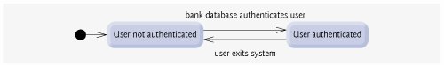
The arrows with stick arrowheads indicate transitions between states. An object can transition from one state to another in response to various events that occur in the system. The name or description of the event that causes a transition is written near the line that corresponds to the transition. For example, the ATM object changes from the "User not authenticated" state to the "User authenticated" state after the database authenticates the user. Recall from the requirements document that the database authenticates a user by comparing the account number and PIN entered by the user with those of the corresponding account in the database. If the database indicates that the user has entered a valid account number and the correct PIN, the ATM object transitions to the "User authenticated" state and changes its userAuthenticated attribute to a value of true. When the user exits the system by choosing the "exit" option from the main menu, the ATM object returns to the "User not authenticated" state in preparation for the next ATM user.
Software Engineering Observation 5.3
 |
Software designers do not generally create state diagrams showing every possible state and state transition for all attributesthere are simply too many of them. State diagrams typically show only the most important or complex states and state transitions. |
Activity Diagrams
Like a state diagram, an activity diagram models aspects of system behavior. Unlike a state diagram, an activity diagram models an object's workflow (sequence of events) during program execution. An activity diagram models the actions the object will perform and in what order. Recall that we used UML activity diagrams to illustrate the flow of control for the control statements presented in Chapter 4 and Chapter 5.
The activity diagram in Fig. 5.27 models the actions involved in executing a BalanceInquiry transaction. We assume that a BalanceInquiry object has already been initialized and assigned a valid account number (that of the current user), so the object knows which balance to retrieve. The diagram includes the actions that occur after the user selects a balance inquiry from the main menu and before the ATM returns the user to the main menua BalanceInquiry object does not perform or initiate these actions, so we do not model them here. The diagram begins with retrieving the available balance of the user's account from the database. Next, the BalanceInquiry retrieves the total balance of the account. Finally, the transaction displays the balances on the screen. This action completes the execution of the transaction.
Figure 5.27. Activity diagram for a BalanceInquiry transaction.
(This item is displayed on page 223 in the print version)
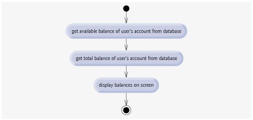
The UML represents an action in an activity diagram as an action state modeled by a rectangle with its left and right sides replaced by arcs curving outward. Each action state contains an action expressionfor example, "get available balance of user's account from database"that specifies an action to be performed. An arrow with a stick arrowhead connects two action states, indicating the order in which the actions represented by the action states occur. The solid circle (at the top of Fig. 5.27) represents the activity's initial statethe beginning of the workflow before the object performs the modeled actions. In this case, the transaction first executes the "get available balance of user's account from database" action expression. Second, the transaction retrieves the total balance. Finally, the transaction displays both balances on the screen. The solid circle enclosed in an open circle (at the bottom of Fig. 5.27) represents the final statethe end of the workflow after the object performs the modeled actions.
Figure 5.28 shows an activity diagram for a Withdrawal transaction. We assume that a Withdrawal object has been assigned a valid account number. We do not model the user selecting a withdrawal from the main menu or the ATM returning the user to the main menu because these are not actions performed by a Withdrawal object. The transaction first displays a menu of standard withdrawal amounts (Fig. 2.17) and an option to cancel the transaction. The transaction then inputs a menu selection from the user. The activity flow now arrives at a decision symbol. This point determines the next action based on the associated guard conditions. If the user cancels the transaction, the system displays an appropriate message. Next, the cancellation flow reaches a merge symbol, where this activity flow joins the transaction's other possible activity flows (which we discuss shortly). Note that a merge can have any number of incoming transition arrows, but only one outgoing transition arrow. The decision at the bottom of the diagram determines whether the transaction should repeat from the beginning. When the user has canceled the transaction, the guard condition "cash dispensed or user canceled transaction" is true, so control transitions to the activity's final state.
Figure 5.28. Activity diagram for a Withdrawal TRansaction.
(This item is displayed on page 225 in the print version)
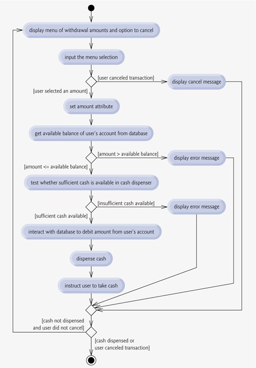
If the user selects a withdrawal amount from the menu, the transaction sets amount (an attribute of class Withdrawal originally modeled in Fig. 4.24) to the value chosen by the user. The transaction next gets the available balance of the user's account (i.e., the availableBalance attribute of the user's Account object) from the database. The activity flow then arrives at another decision. If the requested withdrawal amount exceeds the user's available balance, the system displays an appropriate error message informing the user of the problem. Control then merges with the other activity flows before reaching the decision at the bottom of the diagram. The guard decision "cash not dispensed and user did not cancel" is true, so the activity flow returns to the top of the diagram, and the transaction prompts the user to input a new amount.
If the requested withdrawal amount is less than or equal to the user's available balance, the transaction tests whether the cash dispenser has enough cash to satisfy the withdrawal request. If it does not, the transaction displays an appropriate error message and passes through the merge before reaching the final decision. Cash was not dispensed, so the activity flow returns to the beginning of the activity diagram, and the transaction prompts the user to choose a new amount. If sufficient cash is available, the transaction interacts with the database to debit the withdrawal amount from the user's account (i.e., subtract the amount from both the availableBalance and totalBalance attributes of the user's Account object). The transaction then dispenses the desired amount of cash and instructs the user to take the cash that is dispensed. The main flow of activity next merges with the two error flows and the cancellation flow. In this case, cash was dispensed, so the activity flow reaches the final state.
We have taken the first steps in modeling the behavior of the ATM system and have shown how an object's attributes participate in the object's activities. In Section 6.22, we investigate the operations of our classes to create a more complete model of the system's behavior.
Software Engineering Case Study Self-Review Exercises
| 5.1 |
State whether the following statement is true or false, and if false, explain why: State diagrams model structural aspects of a system. |
| 5.2 |
An activity diagram models the_________that an object performs and the order in which it performs them.
|
| 5.3 |
Based on the requirements document, create an activity diagram for a deposit transaction. |
Answers to Software Engineering Case Study Self-Review Exercises
| 5.1 |
False. State diagrams model some of the behavior of a system. |
| 5.2 |
a. |
| 5.3 |
Figure 5.29 presents an activity diagram for a deposit transaction. The diagram models the actions that occur after the user chooses the deposit option from the main menu and before the ATM returns the user to the main menu. Recall that part of receiving a deposit amount from the user involves converting an integer number of cents to a dollar amount. Also recall that crediting a deposit amount to an account involves increasing only the totalBalance attribute of the user's Account object. The bank updates the availableBalance attribute of the user's Account object only after confirming the amount of cash in the deposit envelope and after the enclosed checks clearthis occurs independently of the ATM system. Figure 5.29. Activity diagram for a Deposit TRansaction. (This item is displayed on page 227 in the print version) 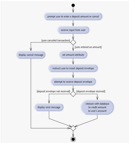
|
Introduction to Computers, the Internet and World Wide Web
- Introduction
- What Is a Computer?
- Computer Organization
- Early Operating Systems
- Personal, Distributed and Client/Server Computing
- The Internet and the World Wide Web
- Machine Languages, Assembly Languages and High-Level Languages
- History of C and C++
- C++ Standard Library
- History of Java
- FORTRAN, COBOL, Pascal and Ada
- Basic, Visual Basic, Visual C++, C# and .NET
- Key Software Trend: Object Technology
- Typical C++ Development Environment
- Notes About C++ and C++ How to Program, 5/e
- Test-Driving a C++ Application
- Software Engineering Case Study: Introduction to Object Technology and the UML (Required)
- Wrap-Up
- Web Resources
- Summary
- Terminology
- Self-Review Exercises
- Exercises
Introduction to C++ Programming
- Introduction
- First Program in C++: Printing a Line of Text
- Modifying Our First C++ Program
- Another C++ Program: Adding Integers
- Memory Concepts
- Arithmetic
- Decision Making: Equality and Relational Operators
- (Optional) Software Engineering Case Study: Examining the ATM Requirements Document
- Wrap-Up
- Summary
- Terminology
- Self-Review Exercises
- Exercises
Introduction to Classes and Objects
- Introduction
- Classes, Objects, Member Functions and Data Members
- Overview of the Chapter Examples
- Defining a Class with a Member Function
- Defining a Member Function with a Parameter
- Data Members, set Functions and get Functions
- Initializing Objects with Constructors
- Placing a Class in a Separate File for Reusability
- Separating Interface from Implementation
- Validating Data with set Functions
- (Optional) Software Engineering Case Study: Identifying the Classes in the ATM Requirements Document
- Wrap-Up
- Summary
- Terminology
- Self-Review Exercises
- Exercises
Control Statements: Part 1
- Introduction
- Algorithms
- Pseudocode
- Control Structures
- if Selection Statement
- if...else Double-Selection Statement
- while Repetition Statement
- Formulating Algorithms: Counter-Controlled Repetition
- Formulating Algorithms: Sentinel-Controlled Repetition
- Formulating Algorithms: Nested Control Statements
- Assignment Operators
- Increment and Decrement Operators
- (Optional) Software Engineering Case Study: Identifying Class Attributes in the ATM System
- Wrap-Up
- Summary
- Terminology
- Self-Review Exercises
- Exercises
Control Statements: Part 2
- Introduction
- Essentials of Counter-Controlled Repetition
- for Repetition Statement
- Examples Using the for Statement
- do...while Repetition Statement
- switch Multiple-Selection Statement
- break and continue Statements
- Logical Operators
- Confusing Equality (==) and Assignment (=) Operators
- Structured Programming Summary
- (Optional) Software Engineering Case Study: Identifying Objects States and Activities in the ATM System
- Wrap-Up
- Summary
- Terminology
- Self-Review Exercises
- Exercises
Functions and an Introduction to Recursion
- Introduction
- Program Components in C++
- Math Library Functions
- Function Definitions with Multiple Parameters
- Function Prototypes and Argument Coercion
- C++ Standard Library Header Files
- Case Study: Random Number Generation
- Case Study: Game of Chance and Introducing enum
- Storage Classes
- Scope Rules
- Function Call Stack and Activation Records
- Functions with Empty Parameter Lists
- Inline Functions
- References and Reference Parameters
- Default Arguments
- Unary Scope Resolution Operator
- Function Overloading
- Function Templates
- Recursion
- Example Using Recursion: Fibonacci Series
- Recursion vs. Iteration
- (Optional) Software Engineering Case Study: Identifying Class Operations in the ATM System
- Wrap-Up
- Summary
- Terminology
- Self-Review Exercises
- Exercises
Arrays and Vectors
- Introduction
- Arrays
- Declaring Arrays
- Examples Using Arrays
- Passing Arrays to Functions
- Case Study: Class GradeBook Using an Array to Store Grades
- Searching Arrays with Linear Search
- Sorting Arrays with Insertion Sort
- Multidimensional Arrays
- Case Study: Class GradeBook Using a Two-Dimensional Array
- Introduction to C++ Standard Library Class Template vector
- (Optional) Software Engineering Case Study: Collaboration Among Objects in the ATM System
- Wrap-Up
- Summary
- Terminology
- Self-Review Exercises
- Exercises
- Recursion Exercises
- vector Exercises
Pointers and Pointer-Based Strings
- Introduction
- Pointer Variable Declarations and Initialization
- Pointer Operators
- Passing Arguments to Functions by Reference with Pointers
- Using const with Pointers
- Selection Sort Using Pass-by-Reference
- sizeof Operators
- Pointer Expressions and Pointer Arithmetic
- Relationship Between Pointers and Arrays
- Arrays of Pointers
- Case Study: Card Shuffling and Dealing Simulation
- Function Pointers
- Introduction to Pointer-Based String Processing
- Wrap-Up
- Summary
- Terminology
- Self-Review Exercises
- Exercises
- Special Section: Building Your Own Computer
- More Pointer Exercises
- String-Manipulation Exercises
- Special Section: Advanced String-Manipulation Exercises
- A Challenging String-Manipulation Project
Classes: A Deeper Look, Part 1
- Introduction
- Time Class Case Study
- Class Scope and Accessing Class Members
- Separating Interface from Implementation
- Access Functions and Utility Functions
- Time Class Case Study: Constructors with Default Arguments
- Destructors
- When Constructors and Destructors Are Called
- Time Class Case Study: A Subtle TrapReturning a Reference to a private Data Member
- Default Memberwise Assignment
- Software Reusability
- (Optional) Software Engineering Case Study: Starting to Program the Classes of the ATM System
- Wrap-Up
- Summary
- Terminology
- Self-Review Exercises
- Exercises
Classes: A Deeper Look, Part 2
- Introduction
- const (Constant) Objects and const Member Functions
- Composition: Objects as Members of Classes
- friend Functions and friend Classes
- Using the this Pointer
- Dynamic Memory Management with Operators new and delete
- static Class Members
- Data Abstraction and Information Hiding
- Container Classes and Iterators
- Proxy Classes
- Wrap-Up
- Summary
- Terminology
- Self-Review Exercises
- Exercises
Operator Overloading; String and Array Objects
- Introduction
- Fundamentals of Operator Overloading
- Restrictions on Operator Overloading
- Operator Functions as Class Members vs. Global Functions
- Overloading Stream Insertion and Stream Extraction Operators
- Overloading Unary Operators
- Overloading Binary Operators
- Case Study: Array Class
- Converting between Types
- Case Study: String Class
- Overloading ++ and --
- Case Study: A Date Class
- Standard Library Class string
- explicit Constructors
- Wrap-Up
- Summary
- Terminology
- Self-Review Exercises
- Exercises
Object-Oriented Programming: Inheritance
- Introduction
- Base Classes and Derived Classes
- protected Members
- Relationship between Base Classes and Derived Classes
- Constructors and Destructors in Derived Classes
- public, protected and private Inheritance
- Software Engineering with Inheritance
- Wrap-Up
- Summary
- Terminology
- Self-Review Exercises
- Exercises
Object-Oriented Programming: Polymorphism
- Introduction
- Polymorphism Examples
- Relationships Among Objects in an Inheritance Hierarchy
- Type Fields and switch Statements
- Abstract Classes and Pure virtual Functions
- Case Study: Payroll System Using Polymorphism
- (Optional) Polymorphism, Virtual Functions and Dynamic Binding Under the Hood
- Case Study: Payroll System Using Polymorphism and Run-Time Type Information with Downcasting, dynamic_cast, typeid and type_info
- Virtual Destructors
- (Optional) Software Engineering Case Study: Incorporating Inheritance into the ATM System
- Wrap-Up
- Summary
- Terminology
- Self-Review Exercises
- Exercises
Templates
- Introduction
- Function Templates
- Overloading Function Templates
- Class Templates
- Nontype Parameters and Default Types for Class Templates
- Notes on Templates and Inheritance
- Notes on Templates and Friends
- Notes on Templates and static Members
- Wrap-Up
- Summary
- Terminology
- Self-Review Exercises
- Exercises
Stream Input/Output
- Introduction
- Streams
- Stream Output
- Stream Input
- Unformatted I/O using read, write and gcount
- Introduction to Stream Manipulators
- Stream Format States and Stream Manipulators
- Stream Error States
- Tying an Output Stream to an Input Stream
- Wrap-Up
- Summary
- Terminology
- Self-Review Exercises
- Exercises
Exception Handling
- Introduction
- Exception-Handling Overview
- Example: Handling an Attempt to Divide by Zero
- When to Use Exception Handling
- Rethrowing an Exception
- Exception Specifications
- Processing Unexpected Exceptions
- Stack Unwinding
- Constructors, Destructors and Exception Handling
- Exceptions and Inheritance
- Processing new Failures
- Class auto_ptr and Dynamic Memory Allocation
- Standard Library Exception Hierarchy
- Other Error-Handling Techniques
- Wrap-Up
- Summary
- Terminology
- Self-Review Exercises
- Exercises
File Processing
- Introduction
- The Data Hierarchy
- Files and Streams
- Creating a Sequential File
- Reading Data from a Sequential File
- Updating Sequential Files
- Random-Access Files
- Creating a Random-Access File
- Writing Data Randomly to a Random-Access File
- Reading from a Random-Access File Sequentially
- Case Study: A Transaction-Processing Program
- Input/Output of Objects
- Wrap-Up
- Summary
- Terminology
- Self-Review Exercises
- Exercises
Class string and String Stream Processing
- Introduction
- string Assignment and Concatenation
- Comparing strings
- Substrings
- Swapping strings
- string Characteristics
- Finding Strings and Characters in a string
- Replacing Characters in a string
- Inserting Characters into a string
- Conversion to C-Style Pointer-Based char * Strings
- Iterators
- String Stream Processing
- Wrap-Up
- Summary
- Terminology
- Self-Review Exercises
- Exercises
Web Programming
- Introduction
- HTTP Request Types
- Multitier Architecture
- Accessing Web Servers
- Apache HTTP Server
- Requesting XHTML Documents
- Introduction to CGI
- Simple HTTP Transactions
- Simple CGI Scripts
- Sending Input to a CGI Script
- Using XHTML Forms to Send Input
- Other Headers
- Case Study: An Interactive Web Page
- Cookies
- Server-Side Files
- Case Study: Shopping Cart
- Wrap-Up
- Internet and Web Resources
- Summary
- Terminology
- Self-Review Exercises
- Exercises
Searching and Sorting
- Introduction
- Searching Algorithms
- Sorting Algorithms
- Wrap-Up
- Summary
- Terminology
- Self-Review Exercises
- Exercises
Data Structures
- Introduction
- Self-Referential Classes
- Dynamic Memory Allocation and Data Structures
- Linked Lists
- Stacks
- Queues
- Trees
- Wrap-Up
- Summary
- Terminology
- Self-Review Exercises
- Exercises
- Special Section: Building Your Own Compiler
Bits, Characters, C-Strings and structs
- Introduction
- Structure Definitions
- Initializing Structures
- Using Structures with Functions
- typedef
- Example: High-Performance Card Shuffling and Dealing Simulation
- Bitwise Operators
- Bit Fields
- Character-Handling Library
- Pointer-Based String-Conversion Functions
- Search Functions of the Pointer-Based String-Handling Library
- Memory Functions of the Pointer-Based String-Handling Library
- Wrap-Up
- Summary
- Terminology
- Self-Review Exercises
- Exercises
Standard Template Library (STL)
- Introduction to the Standard Template Library (STL)
- Sequence Containers
- Associative Containers
- Container Adapters
- Algorithms
- Class bitset
- Function Objects
- Wrap-Up
- STL Internet and Web Resources
- Summary
- Terminology
- Self-Review Exercises
- Exercises
- Recommended Reading
Other Topics
- Introduction
- const_cast Operator
- namespaces
- Operator Keywords
- mutable Class Members
- Pointers to Class Members (.* and ->*)
- Multiple Inheritance
- Multiple Inheritance and virtual Base Classes
- Wrap-Up
- Closing Remarks
- Summary
- Terminology
- Self-Review Exercises
- Exercises
Appendix A. Operator Precedence and Associativity Chart
Appendix B. ASCII Character Set
Appendix C. Fundamental Types
Appendix D. Number Systems
- D.1. Introduction
- D.2. Abbreviating Binary Numbers as Octal and Hexadecimal Numbers
- D.3. Converting Octal and Hexadecimal Numbers to Binary Numbers
- D.4. Converting from Binary, Octal or Hexadecimal to Decimal
- D.5. Converting from Decimal to Binary, Octal or Hexadecimal
- D.6. Negative Binary Numbers: Twos Complement Notation
- Summary
- Terminology
- Self-Review Exercises
- Exercises
Appendix E. C Legacy Code Topics
- E.1. Introduction
- E.2. Redirecting Input/Output on UNIX/LINUX/Mac OS X and Windows Systems
- E.3. Variable-Length Argument Lists
- E.4. Using Command-Line Arguments
- E.5. Notes on Compiling Multiple-Source-File Programs
- E.6. Program Termination with exit and atexit
- E.7. The volatile Type Qualifier
- E.8. Suffixes for Integer and Floating-Point Constants
- E.9. Signal Handling
- E.10. Dynamic Memory Allocation with calloc and realloc
- E.11. The Unconditional Branch: goto
- E.12. Unions
- E.13. Linkage Specifications
- E.14. Wrap-Up
- Summary
- Terminology
- Self-Review Exercises
- Exercises
Appendix F. Preprocessor
- F.1. Introduction
- F.2. The #include Preprocessor Directive
- F.3. The #define Preprocessor Directive: Symbolic Constants
- F.4. The #define Preprocessor Directive: Macros
- F.5. Conditional Compilation
- F.6. The #error and #pragma Preprocessor Directives
- F.7. The # and ## Operators
- F.8. Predefined Symbolic Constants
- F.9. Assertions
- F.10. Wrap-Up
- Summary
- Terminology
- Self-Review Exercises
- Exercises
Appendix G. ATM Case Study Code
- Appendix G. ATM Case Study Code
- G.1. ATM Case Study Implementation
- G.2. Class ATM
- G.3. Class Screen
- G.4. Class Keypad
- G.5. Class CashDispenser
- G.6. Class DepositSlot
- G.7. Class Account
- G.8. Class BankDatabase
- G.9. Class Transaction
- G.10. Class BalanceInquiry
- G.11. Class Withdrawal
- G.12. Class Deposit
- G.13. Test Program ATMCaseStudy.cpp
- G.14. Wrap-Up
Appendix H. UML 2: Additional Diagram Types
Appendix I. C++ Internet and Web Resources
- Appendix I. C++ Internet and Web Resources
- I.1. Resources
- I.2. Tutorials
- I.3. FAQs
- I.4. Visual C++
- I.5. Newsgroups
- I.6. Compilers and Development Tools
- I.7. Standard Template Library
Appendix J. Introduction to XHTML
- J.1. Introduction
- J.2. Editing XHTML
- J.3. First XHTML Example
- J.4. Headers
- J.5. Linking
- J.6. Images
- J.7. Special Characters and More Line Breaks
- J.8. Unordered Lists
- J.9. Nested and Ordered Lists
- J.10. Basic XHTML Tables
- J.11. Intermediate XHTML Tables and Formatting
- J.12. Basic XHTML Forms
- J.13. More Complex XHTML Forms
- J.14. Internet and World Wide Web Resources
- Summary
- Terminology
Appendix K. XHTML Special Characters
Appendix L. Using the Visual Studio .NET Debugger
- L.1. Introduction
- L.2. Breakpoints and the Continue Command
- L.3. The Locals and Watch Windows
- L.4. Controlling Execution Using the Step Into, Step Over, Step Out and Continue Commands
- L.5. The Autos Window
- L.6. Wrap-Up
- Summary
- Terminology
- Self-Review Exercises
Appendix M. Using the GNU C++ Debugger
- M.1. Introduction
- M.2. Breakpoints and the run, stop, continue and print Commands
- M.3. The print and set Commands
- M.4. Controlling Execution Using the step, finish and next Commands
- M.5. The watch Command
- M.6. Wrap-Up
- Summary
- Terminology
- Self-Review Exercises
Bibliography
EAN: 2147483647
Pages: 627
