(Optional) Software Engineering Case Study: Identifying the Classes in the ATM Requirements Document
(Optional) Software Engineering Case Study Identifying the Classes in the ATM Requirements Document
Now we begin designing the ATM system that we introduced in Chapter 2. In this section, we identify the classes that are needed to build the ATM system by analyzing the nouns and noun phrases that appear in the requirements document. We introduce UML class diagrams to model the relationships between these classes. This is an important first step in defining the structure of our system.
Identifying the Classes in a System
We begin our OOD process by identifying the classes required to build the ATM system. We will eventually describe these classes using UML class diagrams and implement these classes in C++. First, we review the requirements document of Section 2.8 and find key nouns and noun phrases to help us identify classes that comprise the ATM system. We may decide that some of these nouns and noun phrases are attributes of other classes in the system. We may also conclude that some of the nouns do not correspond to parts of the system and thus should not be modeled at all. Additional classes may become apparent to us as we proceed through the design process.
Figure 3.18 lists the nouns and noun phrases in the requirements document. We list them from left to right in the order in which they appear in the requirements document. We list only the singular form of each noun or noun phrase.
We create classes only for the nouns and noun phrases that have significance in the ATM system. We do not need to model "bank" as a class, because the bank is not a part of the ATM systemthe bank simply wants us to build the ATM. "Customer" and "user" also represent entities outside of the systemthey are important because they interact with our ATM system, but we do not need to model them as classes in the ATM software. Recall that we modeled an ATM user (i.e., a bank customer) as the actor in the use case diagram of Fig. 2.18.
We do not model "$20 bill" or "deposit envelope" as classes. These are physical objects in the real world, but they are not part of what is being automated. We can adequately represent the presence of bills in the system using an attribute of the class that models the cash dispenser. (We assign attributes to classes in Section 4.13.) For example, the cash dispenser maintains a count of the number of bills it contains. The requirements document does not say anything about what the system should do with deposit envelopes after it receives them. We can assume that simply acknowledging the receipt of an envelopean operation performed by the class that models the deposit slotis sufficient to represent the presence of an envelope in the system. (We assign operations to classes in Section 6.22.)
|
Nouns and noun phrases in the requirements document |
||
|---|---|---|
|
bank |
money / fund |
account number |
|
ATM |
screen |
PIN |
|
user |
keypad |
bank database |
|
customer |
cash dispenser |
balance inquiry |
|
transaction |
$20 bill / cash |
withdrawal |
|
account |
deposit slot |
deposit |
|
balance |
deposit envelope |
|
In our simplified ATM system, representing various amounts of "money," including the "balance" of an account, as attributes of other classes seems most appropriate. Likewise, the nouns "account number" and "PIN" represent significant pieces of information in the ATM system. They are important attributes of a bank account. They do not, however, exhibit behaviors. Thus, we can most appropriately model them as attributes of an account class.
Though the requirements document frequently describes a "transaction" in a general sense, we do not model the broad notion of a financial transaction at this time. Instead, we model the three types of transactions (i.e., "balance inquiry," "withdrawal" and "deposit") as individual classes. These classes possess specific attributes needed for executing the transactions they represent. For example, a withdrawal needs to know the amount of money the user wants to withdraw. A balance inquiry, however, does not require any additional data. Furthermore, the three transaction classes exhibit unique behaviors. A withdrawal includes dispensing cash to the user, whereas a deposit involves receiving deposit envelopes from the user. [Note: In Section 13.10, we "factor out" common features of all transactions into a general "transaction" class using the object-oriented concepts of abstract classes and inheritance.]
We determine the classes for our system based on the remaining nouns and noun phrases from Fig. 3.18. Each of these refers to one or more of the following:
- ATM
- screen
- keypad
- cash dispenser
- deposit slot
- account
- bank database
- balance inquiry
- withdrawal
- deposit
The elements of this list are likely to be classes we will need to implement our system.
We can now model the classes in our system based on the list we have created. We capitalize class names in the design processa UML conventionas we will do when we write the actual C++ code that implements our design. If the name of a class contains more than one word, we run the words together and capitalize each word (e.g., MultipleWordName). Using this convention, we create classes ATM, Screen, Keypad, CashDispenser, DepositSlot, Account, BankDatabase, BalanceInquiry, Withdrawal and Deposit. We construct our system using all of these classes as building blocks. Before we begin building the system, however, we must gain a better understanding of how the classes relate to one another.
Modeling Classes
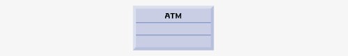
The UML enables us to model, via class diagrams, the classes in the ATM system and their interrelationships. Figure 3.19 represents class ATM. In the UML, each class is modeled as a rectangle with three compartments. The top compartment contains the name of the class, centered horizontally and in boldface. The middle compartment contains the class's attributes. (We discuss attributes in Section 4.13 and Section 5.11.) The bottom compartment contains the class's operations (discussed in Section 6.22). In Fig. 3.19 the middle and bottom compartments are empty, because we have not yet determined this class's attributes and operations.
Figure 3.19. Representing a class in the UML using a class diagram.
Class diagrams also show the relationships between the classes of the system. Figure 3.20 shows how our classes ATM and Withdrawal relate to one another. For the moment, we choose to model only this subset of classes for simplicity. We present a more complete class diagram later in this section. Notice that the rectangles representing classes in this diagram are not subdivided into compartments. The UML allows the suppression of class attributes and operations in this manner, when appropriate, to create more readable diagrams. Such a diagram is said to be an elided diagramone in which some information, such as the contents of the second and third compartments, is not modeled. We will place information in these compartments in Section 4.13 and Section 6.22
Figure 3.20. Class diagram showing an association among classes.

In Fig. 3.20, the solid line that connects the two classes represents an associationa relationship between classes. The numbers near each end of the line are multiplicity values, which indicate how many objects of each class participate in the association. In this case, following the line from one end to the other reveals that, at any given moment, one ATM object participates in an association with either zero or one Withdrawal objectszero if the current user is not currently performing a transaction or has requested a different type of transaction, and one if the user has requested a withdrawal. The UML can model many types of multiplicity. Figure 3.21 lists and explains the multiplicity types.
An association can be named. For example, the word Executes above the line connecting classes ATM and Withdrawal in Fig. 3.20 indicates the name of that association. This part of the diagram reads "one object of class ATM executes zero or one objects of class Withdrawal." Note that association names are directional, as indicated by the filled arrow-headso it would be improper, for example, to read the preceding association from right to left as "zero or one objects of class Withdrawal execute one object of class ATM."
The word currentTransaction at the Withdrawal end of the association line in Fig. 3.20 is a role name, which identifies the role the Withdrawal object plays in its relationship with the ATM. A role name adds meaning to an association between classes by identifying the role a class plays in the context of an association. A class can play several roles in the same system. For example, in a school personnel system, a person may play the role of "professor" when relating to students. The same person may take on the role of "colleague" when participating in a relationship with another professor, and "coach" when coaching student athletes. In Fig. 3.20, the role name currentTransaction indicates that the Withdrawal object participating in the Executes association with an object of class ATM represents the transaction currently being processed by the ATM. In other contexts, a Withdrawal object may take on other roles (e.g., the previous transaction). Notice that we do not specify a role name for the ATM end of the Executes association. Role names in class diagrams are often omitted when the meaning of an association is clear without them.
In addition to indicating simple relationships, associations can specify more complex relationships, such as objects of one class being composed of objects of other classes. Consider a real-world automated teller machine. What "pieces" does a manufacturer put together to build a working ATM? Our requirements document tells us that the ATM is composed of a screen, a keypad, a cash dispenser and a deposit slot.
|
Symbol |
Meaning |
|---|---|
|
0 |
None |
|
1 |
One |
|
m |
An integer value |
|
0..1 |
Zero or one |
|
m, n |
m or n |
|
m..n |
At least m, but not more than n |
|
* |
Any nonnegative integer (zero or more) |
|
0..* |
Zero or more (identical to *) |
|
1..* |
One or more |
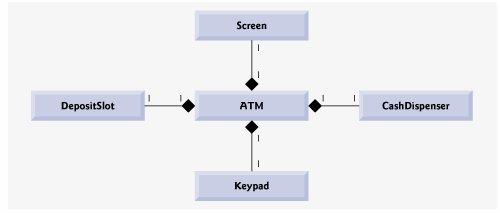
In Fig. 3.22, the solid diamonds attached to the association lines of class ATM indicate that class ATM has a composition relationship with classes Screen, Keypad, CashDispenser and DepositSlot. Composition implies a whole/part relationship. The class that has the composition symbol (the solid diamond) on its end of the association line is the whole (in this case, ATM), and the classes on the other end of the association lines are the partsin this case, classes Screen, Keypad, CashDispenser and DepositSlot. The compositions in Fig. 3.22 indicate that an object of class ATM is formed from one object of class Screen, one object of class CashDispenser, one object of class Keypad and one object of class DepositSlot. The ATM "has a" screen, a keypad, a cash dispenser and a deposit slot. The "has-a" relationship defines composition. (We will see in the "Software Engineering Case Study" section in Chapter 13 that the "is-a" relationship defines inheritance.)
Figure 3.22. Class diagram showing composition relationships.
According to the UML specification, composition relationships have the following properties:
- Only one class in the relationship can represent the whole (i.e., the diamond can be placed on only one end of the association line). For example, either the screen is part of the ATM or the ATM is part of the screen, but the screen and the ATM cannot both represent the whole in the relationship.
- The parts in the composition relationship exist only as long as the whole, and the whole is responsible for the creation and destruction of its parts. For example, the act of constructing an ATM includes manufacturing its parts. Furthermore, if the ATM is destroyed, its screen, keypad, cash dispenser and deposit slot are also destroyed.
- A part may belong to only one whole at a time, although the part may be removed and attached to another whole, which then assumes responsibility for the part.
The solid diamonds in our class diagrams indicate composition relationships that fulfill these three properties. If a "has-a" relationship does not satisfy one or more of these criteria, the UML specifies that hollow diamonds be attached to the ends of association lines to indicate aggregationa weaker form of composition. For example, a personal computer and a computer monitor participate in an aggregation relationshipthe computer "has a" monitor, but the two parts can exist independently, and the same monitor can be attached to multiple computers at once, thus violating the second and third properties of composition.
Figure 3.23 shows a class diagram for the ATM system. This diagram models most of the classes that we identified earlier in this section, as well as the associations between them that we can infer from the requirements document. [Note: Classes BalanceInquiry and Deposit participate in associations similar to those of class Withdrawal, so we have chosen to omit them from this diagram to keep it simple. In Chapter 13, we expand our class diagram to include all the classes in the ATM system.]
Figure 3.23. Class diagram for the ATM system model.
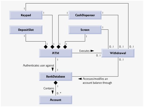
Figure 3.23 presents a graphical model of the structure of the ATM system. This class diagram includes classes BankDatabase and Account, and several associations that were not present in either Fig. 3.20 or Fig. 3.22. The class diagram shows that class ATM has a one-to-one relationship with class BankDatabaseone ATM object authenticates users against one BankDatabase object. In Fig. 3.23, we also model the fact that the bank's database contains information about many accountsone object of class BankDatabase participates in a composition relationship with zero or more objects of class Account. Recall from Fig. 3.21 that the multiplicity value 0..* at the Account end of the association between class BankDatabase and class Account indicates that zero or more objects of class Account take part in the association. Class BankDatabase has a one-to-many relationship with class Accountthe BankDatabase stores many Accounts. Similarly, class Account has a many-to-one relationship with class BankDatabasethere can be many Accounts stored in the BankDatabase. [Note: Recall from Fig. 3.21 that the multiplicity value * is identical to 0..*. We include 0..* in our class diagrams for clarity.]
Figure 3.23 also indicates that if the user is performing a withdrawal, "one object of class Withdrawal accesses/modifies an account balance through one object of class BankDatabase." We could have created an association directly between class Withdrawal and class Account. The requirements document, however, states that the "ATM must interact with the bank's account information database" to perform transactions. A bank account contains sensitive information, and systems engineers must always consider the security of personal data when designing a system. Thus, only the BankDatabase can access and manipulate an account directly. All other parts of the system must interact with the database to retrieve or update account information (e.g., an account balance).
The class diagram in Fig. 3.23 also models associations between class Withdrawal and classes Screen, CashDispenser and Keypad. A withdrawal transaction includes prompting the user to choose a withdrawal amount and receiving numeric input. These actions require the use of the screen and the keypad, respectively. Furthermore, dispensing cash to the user requires access to the cash dispenser.
Classes BalanceInquiry and Deposit, though not shown in Fig. 3.23, take part in several associations with the other classes of the ATM system. Like class Withdrawal, each of these classes associates with classes ATM and BankDatabase. An object of class BalanceInquiry also associates with an object of class Screen to display the balance of an account to the user. Class Deposit associates with classes Screen, Keypad and DepositSlot. Like withdrawals, deposit transactions require use of the screen and the keypad to display prompts and receive input, respectively. To receive deposit envelopes, an object of class Deposit accesses the deposit slot.
We have now identified the classes in our ATM system (although we may discover others as we proceed with the design and implementation). In Section 4.13, we determine the attributes for each of these classes, and in Section 5.11, we use these attributes to examine how the system changes over time. In Section 6.22, we determine the operations of the classes in our system.
Software Engineering Case Study Self-Review Exercises
| 3.1 |
Suppose we have a class Car that represents a car. Think of some of the different pieces that a manufacturer would put together to produce a whole car. Create a class diagram (similar to Fig. 3.22) that models some of the composition relationships of class Car. |
| 3.2 |
Suppose we have a class File that represents an electronic document in a stand-alone, non-networked computer represented by class Computer. What sort of association exists between class Computer and class File?
|
| 3.3 |
State whether the following statement is true or false, and if false, explain why: A UML diagram in which a class's second and third compartments are not modeled is said to be an elided diagram. |
| 3.4 |
Modify the class diagram of Fig. 3.23 to include class Deposit instead of class Withdrawal. |
Answers to Software Engineering Case Study Self-Review Exercises
| 3.1 |
[Note: Student answers may vary.] Figure 3.24 presents a class diagram that shows some of the composition relationships of a class Car. Figure 3.24. Class diagram showing composition relationships of a class Car. (This item is displayed on page 117 in the print version) 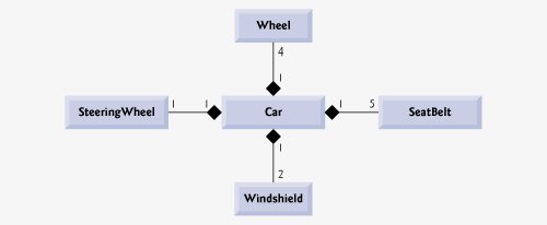
|
| 3.2 |
c. [Note: In a computer network, this relationship could be many-to-many.] |
|
|
|
| 3.3 |
True. |
| 3.4 |
Figure 3.25 presents a class diagram for the ATM including class Deposit instead of class Withdrawal (as in Fig. 3.23). Note that Deposit does not access CashDispenser, but does access DepositSlot. Figure 3.25. Class diagram for the ATM system model including class Deposit. 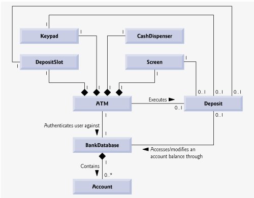
|
Introduction to Computers, the Internet and World Wide Web
- Introduction
- What Is a Computer?
- Computer Organization
- Early Operating Systems
- Personal, Distributed and Client/Server Computing
- The Internet and the World Wide Web
- Machine Languages, Assembly Languages and High-Level Languages
- History of C and C++
- C++ Standard Library
- History of Java
- FORTRAN, COBOL, Pascal and Ada
- Basic, Visual Basic, Visual C++, C# and .NET
- Key Software Trend: Object Technology
- Typical C++ Development Environment
- Notes About C++ and C++ How to Program, 5/e
- Test-Driving a C++ Application
- Software Engineering Case Study: Introduction to Object Technology and the UML (Required)
- Wrap-Up
- Web Resources
- Summary
- Terminology
- Self-Review Exercises
- Exercises
Introduction to C++ Programming
- Introduction
- First Program in C++: Printing a Line of Text
- Modifying Our First C++ Program
- Another C++ Program: Adding Integers
- Memory Concepts
- Arithmetic
- Decision Making: Equality and Relational Operators
- (Optional) Software Engineering Case Study: Examining the ATM Requirements Document
- Wrap-Up
- Summary
- Terminology
- Self-Review Exercises
- Exercises
Introduction to Classes and Objects
- Introduction
- Classes, Objects, Member Functions and Data Members
- Overview of the Chapter Examples
- Defining a Class with a Member Function
- Defining a Member Function with a Parameter
- Data Members, set Functions and get Functions
- Initializing Objects with Constructors
- Placing a Class in a Separate File for Reusability
- Separating Interface from Implementation
- Validating Data with set Functions
- (Optional) Software Engineering Case Study: Identifying the Classes in the ATM Requirements Document
- Wrap-Up
- Summary
- Terminology
- Self-Review Exercises
- Exercises
Control Statements: Part 1
- Introduction
- Algorithms
- Pseudocode
- Control Structures
- if Selection Statement
- if...else Double-Selection Statement
- while Repetition Statement
- Formulating Algorithms: Counter-Controlled Repetition
- Formulating Algorithms: Sentinel-Controlled Repetition
- Formulating Algorithms: Nested Control Statements
- Assignment Operators
- Increment and Decrement Operators
- (Optional) Software Engineering Case Study: Identifying Class Attributes in the ATM System
- Wrap-Up
- Summary
- Terminology
- Self-Review Exercises
- Exercises
Control Statements: Part 2
- Introduction
- Essentials of Counter-Controlled Repetition
- for Repetition Statement
- Examples Using the for Statement
- do...while Repetition Statement
- switch Multiple-Selection Statement
- break and continue Statements
- Logical Operators
- Confusing Equality (==) and Assignment (=) Operators
- Structured Programming Summary
- (Optional) Software Engineering Case Study: Identifying Objects States and Activities in the ATM System
- Wrap-Up
- Summary
- Terminology
- Self-Review Exercises
- Exercises
Functions and an Introduction to Recursion
- Introduction
- Program Components in C++
- Math Library Functions
- Function Definitions with Multiple Parameters
- Function Prototypes and Argument Coercion
- C++ Standard Library Header Files
- Case Study: Random Number Generation
- Case Study: Game of Chance and Introducing enum
- Storage Classes
- Scope Rules
- Function Call Stack and Activation Records
- Functions with Empty Parameter Lists
- Inline Functions
- References and Reference Parameters
- Default Arguments
- Unary Scope Resolution Operator
- Function Overloading
- Function Templates
- Recursion
- Example Using Recursion: Fibonacci Series
- Recursion vs. Iteration
- (Optional) Software Engineering Case Study: Identifying Class Operations in the ATM System
- Wrap-Up
- Summary
- Terminology
- Self-Review Exercises
- Exercises
Arrays and Vectors
- Introduction
- Arrays
- Declaring Arrays
- Examples Using Arrays
- Passing Arrays to Functions
- Case Study: Class GradeBook Using an Array to Store Grades
- Searching Arrays with Linear Search
- Sorting Arrays with Insertion Sort
- Multidimensional Arrays
- Case Study: Class GradeBook Using a Two-Dimensional Array
- Introduction to C++ Standard Library Class Template vector
- (Optional) Software Engineering Case Study: Collaboration Among Objects in the ATM System
- Wrap-Up
- Summary
- Terminology
- Self-Review Exercises
- Exercises
- Recursion Exercises
- vector Exercises
Pointers and Pointer-Based Strings
- Introduction
- Pointer Variable Declarations and Initialization
- Pointer Operators
- Passing Arguments to Functions by Reference with Pointers
- Using const with Pointers
- Selection Sort Using Pass-by-Reference
- sizeof Operators
- Pointer Expressions and Pointer Arithmetic
- Relationship Between Pointers and Arrays
- Arrays of Pointers
- Case Study: Card Shuffling and Dealing Simulation
- Function Pointers
- Introduction to Pointer-Based String Processing
- Wrap-Up
- Summary
- Terminology
- Self-Review Exercises
- Exercises
- Special Section: Building Your Own Computer
- More Pointer Exercises
- String-Manipulation Exercises
- Special Section: Advanced String-Manipulation Exercises
- A Challenging String-Manipulation Project
Classes: A Deeper Look, Part 1
- Introduction
- Time Class Case Study
- Class Scope and Accessing Class Members
- Separating Interface from Implementation
- Access Functions and Utility Functions
- Time Class Case Study: Constructors with Default Arguments
- Destructors
- When Constructors and Destructors Are Called
- Time Class Case Study: A Subtle TrapReturning a Reference to a private Data Member
- Default Memberwise Assignment
- Software Reusability
- (Optional) Software Engineering Case Study: Starting to Program the Classes of the ATM System
- Wrap-Up
- Summary
- Terminology
- Self-Review Exercises
- Exercises
Classes: A Deeper Look, Part 2
- Introduction
- const (Constant) Objects and const Member Functions
- Composition: Objects as Members of Classes
- friend Functions and friend Classes
- Using the this Pointer
- Dynamic Memory Management with Operators new and delete
- static Class Members
- Data Abstraction and Information Hiding
- Container Classes and Iterators
- Proxy Classes
- Wrap-Up
- Summary
- Terminology
- Self-Review Exercises
- Exercises
Operator Overloading; String and Array Objects
- Introduction
- Fundamentals of Operator Overloading
- Restrictions on Operator Overloading
- Operator Functions as Class Members vs. Global Functions
- Overloading Stream Insertion and Stream Extraction Operators
- Overloading Unary Operators
- Overloading Binary Operators
- Case Study: Array Class
- Converting between Types
- Case Study: String Class
- Overloading ++ and --
- Case Study: A Date Class
- Standard Library Class string
- explicit Constructors
- Wrap-Up
- Summary
- Terminology
- Self-Review Exercises
- Exercises
Object-Oriented Programming: Inheritance
- Introduction
- Base Classes and Derived Classes
- protected Members
- Relationship between Base Classes and Derived Classes
- Constructors and Destructors in Derived Classes
- public, protected and private Inheritance
- Software Engineering with Inheritance
- Wrap-Up
- Summary
- Terminology
- Self-Review Exercises
- Exercises
Object-Oriented Programming: Polymorphism
- Introduction
- Polymorphism Examples
- Relationships Among Objects in an Inheritance Hierarchy
- Type Fields and switch Statements
- Abstract Classes and Pure virtual Functions
- Case Study: Payroll System Using Polymorphism
- (Optional) Polymorphism, Virtual Functions and Dynamic Binding Under the Hood
- Case Study: Payroll System Using Polymorphism and Run-Time Type Information with Downcasting, dynamic_cast, typeid and type_info
- Virtual Destructors
- (Optional) Software Engineering Case Study: Incorporating Inheritance into the ATM System
- Wrap-Up
- Summary
- Terminology
- Self-Review Exercises
- Exercises
Templates
- Introduction
- Function Templates
- Overloading Function Templates
- Class Templates
- Nontype Parameters and Default Types for Class Templates
- Notes on Templates and Inheritance
- Notes on Templates and Friends
- Notes on Templates and static Members
- Wrap-Up
- Summary
- Terminology
- Self-Review Exercises
- Exercises
Stream Input/Output
- Introduction
- Streams
- Stream Output
- Stream Input
- Unformatted I/O using read, write and gcount
- Introduction to Stream Manipulators
- Stream Format States and Stream Manipulators
- Stream Error States
- Tying an Output Stream to an Input Stream
- Wrap-Up
- Summary
- Terminology
- Self-Review Exercises
- Exercises
Exception Handling
- Introduction
- Exception-Handling Overview
- Example: Handling an Attempt to Divide by Zero
- When to Use Exception Handling
- Rethrowing an Exception
- Exception Specifications
- Processing Unexpected Exceptions
- Stack Unwinding
- Constructors, Destructors and Exception Handling
- Exceptions and Inheritance
- Processing new Failures
- Class auto_ptr and Dynamic Memory Allocation
- Standard Library Exception Hierarchy
- Other Error-Handling Techniques
- Wrap-Up
- Summary
- Terminology
- Self-Review Exercises
- Exercises
File Processing
- Introduction
- The Data Hierarchy
- Files and Streams
- Creating a Sequential File
- Reading Data from a Sequential File
- Updating Sequential Files
- Random-Access Files
- Creating a Random-Access File
- Writing Data Randomly to a Random-Access File
- Reading from a Random-Access File Sequentially
- Case Study: A Transaction-Processing Program
- Input/Output of Objects
- Wrap-Up
- Summary
- Terminology
- Self-Review Exercises
- Exercises
Class string and String Stream Processing
- Introduction
- string Assignment and Concatenation
- Comparing strings
- Substrings
- Swapping strings
- string Characteristics
- Finding Strings and Characters in a string
- Replacing Characters in a string
- Inserting Characters into a string
- Conversion to C-Style Pointer-Based char * Strings
- Iterators
- String Stream Processing
- Wrap-Up
- Summary
- Terminology
- Self-Review Exercises
- Exercises
Web Programming
- Introduction
- HTTP Request Types
- Multitier Architecture
- Accessing Web Servers
- Apache HTTP Server
- Requesting XHTML Documents
- Introduction to CGI
- Simple HTTP Transactions
- Simple CGI Scripts
- Sending Input to a CGI Script
- Using XHTML Forms to Send Input
- Other Headers
- Case Study: An Interactive Web Page
- Cookies
- Server-Side Files
- Case Study: Shopping Cart
- Wrap-Up
- Internet and Web Resources
- Summary
- Terminology
- Self-Review Exercises
- Exercises
Searching and Sorting
- Introduction
- Searching Algorithms
- Sorting Algorithms
- Wrap-Up
- Summary
- Terminology
- Self-Review Exercises
- Exercises
Data Structures
- Introduction
- Self-Referential Classes
- Dynamic Memory Allocation and Data Structures
- Linked Lists
- Stacks
- Queues
- Trees
- Wrap-Up
- Summary
- Terminology
- Self-Review Exercises
- Exercises
- Special Section: Building Your Own Compiler
Bits, Characters, C-Strings and structs
- Introduction
- Structure Definitions
- Initializing Structures
- Using Structures with Functions
- typedef
- Example: High-Performance Card Shuffling and Dealing Simulation
- Bitwise Operators
- Bit Fields
- Character-Handling Library
- Pointer-Based String-Conversion Functions
- Search Functions of the Pointer-Based String-Handling Library
- Memory Functions of the Pointer-Based String-Handling Library
- Wrap-Up
- Summary
- Terminology
- Self-Review Exercises
- Exercises
Standard Template Library (STL)
- Introduction to the Standard Template Library (STL)
- Sequence Containers
- Associative Containers
- Container Adapters
- Algorithms
- Class bitset
- Function Objects
- Wrap-Up
- STL Internet and Web Resources
- Summary
- Terminology
- Self-Review Exercises
- Exercises
- Recommended Reading
Other Topics
- Introduction
- const_cast Operator
- namespaces
- Operator Keywords
- mutable Class Members
- Pointers to Class Members (.* and ->*)
- Multiple Inheritance
- Multiple Inheritance and virtual Base Classes
- Wrap-Up
- Closing Remarks
- Summary
- Terminology
- Self-Review Exercises
- Exercises
Appendix A. Operator Precedence and Associativity Chart
Appendix B. ASCII Character Set
Appendix C. Fundamental Types
Appendix D. Number Systems
- D.1. Introduction
- D.2. Abbreviating Binary Numbers as Octal and Hexadecimal Numbers
- D.3. Converting Octal and Hexadecimal Numbers to Binary Numbers
- D.4. Converting from Binary, Octal or Hexadecimal to Decimal
- D.5. Converting from Decimal to Binary, Octal or Hexadecimal
- D.6. Negative Binary Numbers: Twos Complement Notation
- Summary
- Terminology
- Self-Review Exercises
- Exercises
Appendix E. C Legacy Code Topics
- E.1. Introduction
- E.2. Redirecting Input/Output on UNIX/LINUX/Mac OS X and Windows Systems
- E.3. Variable-Length Argument Lists
- E.4. Using Command-Line Arguments
- E.5. Notes on Compiling Multiple-Source-File Programs
- E.6. Program Termination with exit and atexit
- E.7. The volatile Type Qualifier
- E.8. Suffixes for Integer and Floating-Point Constants
- E.9. Signal Handling
- E.10. Dynamic Memory Allocation with calloc and realloc
- E.11. The Unconditional Branch: goto
- E.12. Unions
- E.13. Linkage Specifications
- E.14. Wrap-Up
- Summary
- Terminology
- Self-Review Exercises
- Exercises
Appendix F. Preprocessor
- F.1. Introduction
- F.2. The #include Preprocessor Directive
- F.3. The #define Preprocessor Directive: Symbolic Constants
- F.4. The #define Preprocessor Directive: Macros
- F.5. Conditional Compilation
- F.6. The #error and #pragma Preprocessor Directives
- F.7. The # and ## Operators
- F.8. Predefined Symbolic Constants
- F.9. Assertions
- F.10. Wrap-Up
- Summary
- Terminology
- Self-Review Exercises
- Exercises
Appendix G. ATM Case Study Code
- Appendix G. ATM Case Study Code
- G.1. ATM Case Study Implementation
- G.2. Class ATM
- G.3. Class Screen
- G.4. Class Keypad
- G.5. Class CashDispenser
- G.6. Class DepositSlot
- G.7. Class Account
- G.8. Class BankDatabase
- G.9. Class Transaction
- G.10. Class BalanceInquiry
- G.11. Class Withdrawal
- G.12. Class Deposit
- G.13. Test Program ATMCaseStudy.cpp
- G.14. Wrap-Up
Appendix H. UML 2: Additional Diagram Types
Appendix I. C++ Internet and Web Resources
- Appendix I. C++ Internet and Web Resources
- I.1. Resources
- I.2. Tutorials
- I.3. FAQs
- I.4. Visual C++
- I.5. Newsgroups
- I.6. Compilers and Development Tools
- I.7. Standard Template Library
Appendix J. Introduction to XHTML
- J.1. Introduction
- J.2. Editing XHTML
- J.3. First XHTML Example
- J.4. Headers
- J.5. Linking
- J.6. Images
- J.7. Special Characters and More Line Breaks
- J.8. Unordered Lists
- J.9. Nested and Ordered Lists
- J.10. Basic XHTML Tables
- J.11. Intermediate XHTML Tables and Formatting
- J.12. Basic XHTML Forms
- J.13. More Complex XHTML Forms
- J.14. Internet and World Wide Web Resources
- Summary
- Terminology
Appendix K. XHTML Special Characters
Appendix L. Using the Visual Studio .NET Debugger
- L.1. Introduction
- L.2. Breakpoints and the Continue Command
- L.3. The Locals and Watch Windows
- L.4. Controlling Execution Using the Step Into, Step Over, Step Out and Continue Commands
- L.5. The Autos Window
- L.6. Wrap-Up
- Summary
- Terminology
- Self-Review Exercises
Appendix M. Using the GNU C++ Debugger
- M.1. Introduction
- M.2. Breakpoints and the run, stop, continue and print Commands
- M.3. The print and set Commands
- M.4. Controlling Execution Using the step, finish and next Commands
- M.5. The watch Command
- M.6. Wrap-Up
- Summary
- Terminology
- Self-Review Exercises
Bibliography
EAN: 2147483647
Pages: 627
