Extra for Experts: Maximal Linear System Response to a Digital Input
Extra for Experts Maximal Linear System Response to a Digital Input
The remainder of this Chapter 1 shall fill with a theorem from linear system theory concerning the worst-case response of linear time-invariant systems when driven by digital signals. This theorem is useful for evaluating, among other things, worst-case crosstalk voltages and worst-case power supply noise voltages. The theorem begins with a rather abstract situation that reduces in the end to a more familiar digital situation.
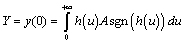
The mathematical model underlying the theorem appears in Figure 1.5. This figure shows an ideal source, producing a waveform x ( t ) with an output limited to the range of ± A . No other requirements are placed upon x ( t ). It may have infinitely fast rise and fall times, it can transition at any time (not limited only to clock intervals), and it may attain intermediate voltages within the range of ±A. The signal x ( t ) is a superset of the class of all digital signals.
Figure 1.5. The maximum output from system H is bounded by equation [1.21]
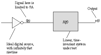
The ideal source output is then presented to a linear, time-invariant system with transfer function H ( f ), corresponding impulse response h ( t ), and step response h ( t ), and step response 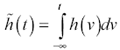 . The output of the linear, time-invariant system is signal y ( t ).
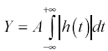
The theorem states a bound Y on the amplitude of y ( t ) that holds for all possible signals x ( t ). Furthermore, this is a constructive theorem in that it also develops at least one particular function x ( t ) that is guaranteed to excite y ( t ) to its maximum value. The bound Y on the output amplitude is
Equation 1.21
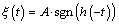
One signal x ( t ) that will cause the bound to be reached is
Equation 1.22
|
where |
the function sgn() is the sign function, |
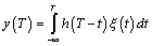
The proof of this solution follows from an examination of the convolution integral for linear, time-invariant systems. The output y ( T ) at time T in response to any excitation is thus defined:
Equation 1.23
If we wish to maximize the output at any particular time T , this integral grants us enormous flexibility to do so. We are free to assign whatever values to x ( t ) we choose, at every point t in time, provided that no value may fall outside the range ±A. Note that the various values of x ( t ) each are used but once inside the integral, with no complicating constraints. They may all be independently assigned. Therefore, the way to maximize the integral is simply to maximize the integrand for each value of t .
For example, the best choice for x ( ) would be whatever value maximizes its elemental contribution to the integral, h ( T “ 0 ) x ( ). If the algebraic sign of h ( T ) is positive, choose x ( ) = + A (the largest possible positive value). If the algebraic sign of h ( T ) is negative, choose x ( ) = “ A. That's all there is to it.
In general, the values for x ( t ) that maximize y at time T are x ( t ) = A sgn( h(T “ t )). In the special case where you wish to maximize the output at time T = 0, equation [1.22] results. Equation [1.21] results from inserting solution [1.22] into equation [1.23], evaluating the result at T = 0, and recognizing that h ( t ) sgn( h ( t )) = h ( t ).
Similar reasoning holds in the reverse algebraic direction. To minimize y , use x ( t ) = -A sgn( h ( T “ t )). For a linear system with symmetrical input (no DC offset), the worst-case positive and negative amplitudes are equal.
Let's extend this theorem to treat some special forms of impulse response. For example, what if the impulse response is everywhere positive? In that case the particular signal that maximizes the response is simply x ( t ) = A , a full-valued, steady-state input. This says that systems with purely positive impulse responses are special. In response to a bounded input, their outputs can never exceed the steady-state maximum output. In other words, they have no overshoot .
The condition h ( t )  0 may also be expressed in terms of the step response. The equivalent condition imposed on the step response is that the step response be monotonic. These three properties, therefore, always go together:
- Nonnegative impulse response
- Monotonic step response
- No overshoot in response to bounded input
What if the impulse response goes negative, but just for a short interval? That would place a dip in the step response, a short interval of nonmonotonic behavior. What happens to the maximum output signal in this case? I'd like to show you this answer and express it in terms directly observable on the step response waveform. To do so requires a little more calculus.
The answer may be found directly from equation [1.23], substituting our known solution for x ( t ), choosing to maximize the response at point T = 0, and substituting a new time variable u = - t .
Equation 1.24
Suppose now that you are given a list of the intervals of time [ pstart n , pend n ] over which h ( u ) were positive, and another list of intervals [ qstart m , qend m ] over which h ( u ) were known to be negative. You could then rewrite the integral as a sum of component integrals:
Equation 1.25
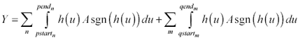
By the construction of the p -intervals, the value of A sgn( h ( u )) within them is always A , so that factor may be pulled out from under the integral. Similarly, over all the q -intervals the value of A sgn( h ( u )) is “A , so that factor may be pulled out as well. The resulting expression looks like this:
Equation 1.26
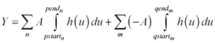
Now you have a series of ordinary integrals of the impulse function of a linear system. Express these integrals in terms of differences between various points on the step response  :
:
Equation 1.27

If you have followed me so far, you will note that each of the terms within the left-hand summation is positive. Each of the terms within the rightmost summation is positive as well, by virtue of having been multiplied by “A . I can therefore eliminate all references to the sign of A by using the absolute value symbol:
Equation 1.28
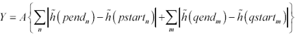
What this equation tells you to do is to first mark out all the maxima and minima on the step response. These are the points where the slope (the impulse response) changes sign. The take the absolute value of the successive differences between each of these extrema and add them up ( D 1 + D 2 + D 3 ...). Multiply by A and you have your answer. That's the biggest output you will ever see in response to a bounded input (Figure 1.6).
Figure 1.6. The response to a bounded excitation can grow larger than step response.
Applying this theory to a real digital system takes a few more manipulations. First, we need to treat the issue of DC offset, because the voltages 0 and V CC , not ± A , generally bound a digital signal. Finally, we need to treat the issue of finite risetime.
The DC offset issue easily succumbs to a superposition analysis. To generate a solution, break the input signal into two components , a DC offset (V CC /2) and an AC signal (with amplitude A = V CC /2). Use your intuition to derive the DC steady-state output ( assuming the driver constantly put out V CC /2). Use the maximal value theorem [1.22] to tell you how much the output may range above or below the DC steady-state output. [2]
[2] This use of superposition works only for linear systems.
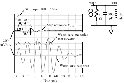
The mathematical model used to solve the finite-risetime part of the problem appears in Figure 1.7.
Figure 1.7. The magnitude of the largest possible response at y ( t ) is a function of the step response of the combined filter G ( f ) H ( f ).
Here the signal x ( t ) is put through a low-pass filter function G ( f ) whose purpose is to round off the (possibly) square edges of x ( t ) such that x ( t ) will never display a transition faster than that allowed by the step response of the filter G ( f ). For a suitable choice of G ( f ), the space of all signals available at x ( t ) includes pretty nearly all the things that could come out of a digital driver with rise and fall time t r . You will want to set up the filter G ( f ) to have a monotonic step response, and unity DC gain, in order that the excursion limits at x match those at x .
As a practical matter, what I do is make a step response measurement from the system under test using the system's own driver as the step source . The system driver therefore implements the function G ( f ) for me. I then mark off the extrema of the step response, measure the magnitudes of the inter-extreme excursions, sum their values, and divide by two (I measured the step response with a driver with range [0, V CC ] for which A = V CC /2; ergo, I scale the measured output by 1/2). The result tells me how much the output may range above or below the DC steady-state output.
This theorem applies to linear, time-invariant systems. It does not apply to limited, clamped, or nonlinear systems, or to systems that change significantly during the time within which the output is created.
It does, however, apply reasonably well to systems with nonlinear totem-pole drivers provided that the driver after each rising edge rapidly attains an output near V CC before the first reflections return from the end of the line. Under this condition the behavior of the driver during the time the signal reflects off the driver is indistinguishable from a simple, linear source connected to V CC , so the theorem applies. The same reasoning applies to drivers that rapidly pull low, attaining a near-zero state prior to the arrival of the first reflections from the far end of the line.
The space of candidate functions x used in the construction of the maximal solution includes all functions that slam back and forth between the given limits, without regard to the times at which they may do so. This space is a superset of the collection of all synchronous waveforms clocked at some fixed rate. Therefore, the upper bound Y is just that, an upper bound on the maximal excursion. It is possible in some situations that the maximal solution function x and its corresponding filtered version x cannot be produced by the target system and are therefore of little or no concern in worst-case analysis. This can happen in systems that have risetimes much shorter than the baud interval. In these cases it's a good idea to examine the waveform x so you can decide whether or not to worry about it.
In the design of high-speed LAN communications systems I have found this theorem to be of great value. In LAN systems the risetime and the baud interval are closely related , and the difference between the calculated Y and the actual, real-world upper bound is negligible.
This discussion highlights an important point about crosstalk in cable systems ”the long, lingering, diddling crosstalk signals that show up in response to a step input can, if excited with a worst-case input, easily be made to build up to significant voltages. Equation [1.28] predicts the worst-case crosstalk response from a single measurement of the step response of the system.
Equation [1.28] is also of great benefit in predicting the worst-case response of a power system to random surges of current. From a single measurement of the step response of a digital system ( swinging from minimum current to maximum current in one quick step) equation [1.28] predicts the worst-case power-supply excursion. This result will always meet or exceed the excursions computed based upon simulations of the power system response using sinusoidal or square-wave excitations.
POINT TO REMEMBER
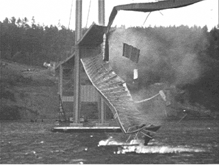
- Resonance affects all physical structures, including bridges (Figure 1.8).
Figure 1.8. The Tacoma Narrows bridge collapsed on July 1, 1940.
For further study see: www.sigcon.com
Fundamentals
- Impedance of Linear, Time-Invariant, Lumped-Element Circuits
- Power Ratios
- Rules of Scaling
- The Concept of Resonance
- Extra for Experts: Maximal Linear System Response to a Digital Input
Transmission Line Parameters
- Transmission Line Parameters
- Telegraphers Equations
- Derivation of Telegraphers Equations
- Ideal Transmission Line
- DC Resistance
- DC Conductance
- Skin Effect
- Skin-Effect Inductance
- Modeling Internal Impedance
- Concentric-Ring Skin-Effect Model
- Proximity Effect
- Surface Roughness
- Dielectric Effects
- Impedance in Series with the Return Path
- Slow-Wave Mode On-Chip
Performance Regions
- Performance Regions
- Signal Propagation Model
- Hierarchy of Regions
- Necessary Mathematics: Input Impedance and Transfer Function
- Lumped-Element Region
- RC Region
- LC Region (Constant-Loss Region)
- Skin-Effect Region
- Dielectric Loss Region
- Waveguide Dispersion Region
- Summary of Breakpoints Between Regions
- Equivalence Principle for Transmission Media
- Scaling Copper Transmission Media
- Scaling Multimode Fiber-Optic Cables
- Linear Equalization: Long Backplane Trace Example
- Adaptive Equalization: Accelerant Networks Transceiver
Frequency-Domain Modeling
- Frequency-Domain Modeling
- Going Nonlinear
- Approximations to the Fourier Transform
- Discrete Time Mapping
- Other Limitations of the FFT
- Normalizing the Output of an FFT Routine
- Useful Fourier Transform-Pairs
- Effect of Inadequate Sampling Rate
- Implementation of Frequency-Domain Simulation
- Embellishments
- Checking the Output of Your FFT Routine
Pcb (printed-circuit board) Traces
- Pcb (printed-circuit board) Traces
- Pcb Signal Propagation
- Limits to Attainable Distance
- Pcb Noise and Interference
- Pcb Connectors
- Modeling Vias
- The Future of On-Chip Interconnections
Differential Signaling
- Differential Signaling
- Single-Ended Circuits
- Two-Wire Circuits
- Differential Signaling
- Differential and Common-Mode Voltages and Currents
- Differential and Common-Mode Velocity
- Common-Mode Balance
- Common-Mode Range
- Differential to Common-Mode Conversion
- Differential Impedance
- Pcb Configurations
- Pcb Applications
- Intercabinet Applications
- LVDS Signaling
Generic Building-Cabling Standards
- Generic Building-Cabling Standards
- Generic Cabling Architecture
- SNR Budgeting
- Glossary of Cabling Terms
- Preferred Cable Combinations
- FAQ: Building-Cabling Practices
- Crossover Wiring
- Plenum-Rated Cables
- Laying Cables in an Uncooled Attic Space
- FAQ: Older Cable Types
100-Ohm Balanced Twisted-Pair Cabling
- 100-Ohm Balanced Twisted-Pair Cabling
- UTP Signal Propagation
- UTP Transmission Example: 10BASE-T
- UTP Noise and Interference
- UTP Connectors
- Issues with Screening
- Category-3 UTP at Elevated Temperature
150-Ohm STP-A Cabling
- 150-Ohm STP-A Cabling
- 150- W STP-A Signal Propagation
- 150- W STP-A Noise and Interference
- 150- W STP-A: Skew
- 150- W STP-A: Radiation and Safety
- 150- W STP-A: Comparison with UTP
- 150- W STP-A Connectors
Coaxial Cabling
- Coaxial Cabling
- Coaxial Signal Propagation
- Coaxial Cable Noise and Interference
- Coaxial Cable Connectors
Fiber-Optic Cabling
- Fiber-Optic Cabling
- Making Glass Fiber
- Finished Core Specifications
- Cabling the Fiber
- Wavelengths of Operation
- Multimode Glass Fiber-Optic Cabling
- Single-Mode Fiber-Optic Cabling
Clock Distribution
- Clock Distribution
- Extra Fries, Please
- Arithmetic of Clock Skew
- Clock Repeaters
- Stripline vs. Microstrip Delay
- Importance of Terminating Clock Lines
- Effect of Clock Receiver Thresholds
- Effect of Split Termination
- Intentional Delay Adjustments
- Driving Multiple Loads with Source Termination
- Daisy-Chain Clock Distribution
- The Jitters
- Power Supply Filtering for Clock Sources, Repeaters, and PLL Circuits
- Intentional Clock Modulation
- Reduced-Voltage Signaling
- Controlling Crosstalk on Clock Lines
- Reducing Emissions
Time-Domain Simulation Tools and Methods
- Ringing in a New Era
- Signal Integrity Simulation Process
- The Underlying Simulation Engine
- IBIS (I/O Buffer Information Specification)
- IBIS: History and Future Direction
- IBIS: Issues with Interpolation
- IBIS: Issues with SSO Noise
- Nature of EMC Work
- Power and Ground Resonance
Points to Remember
Appendix A. Building a Signal Integrity Department
Appendix B. Calculation of Loss Slope
Appendix C. Two-Port Analysis
- Appendix C. Two-Port Analysis
- Simple Cases Involving Transmission Lines
- Fully Configured Transmission Line
- Complicated Configurations
Appendix D. Accuracy of Pi Model
Appendix E. erf( )
Notes
EAN: N/A
Pages: 163
