Hierarchy of Regions
The transmission loss associated with any conductive transmission media increases monotonically with frequency. Sweeping from low frequencies to high, the slope of the loss curve changes in a predictable way as you pass the onset of various regions of operation. The progression of regions, and the transmission performance within each region, is the subject of this chapter.
Alternate forms of transmission structures exist, such as fiber- optic waveguides and various forms of RF waveguides, that cannot convey DC signals. In these alternate structures the loss function must be necessarily be nonmonotonic, leading to a different hierarchy of performance regions. The discussion of regions presented here applies only to conductive transmission structures as normally used in digital applications.
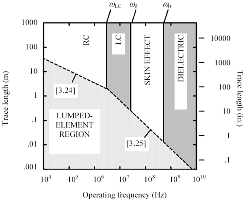
Figure 3.2 illustrates the general arrangement of performance regions pertaining to copper media. The particular data shown in this diagram represents a 150- m m (6-mil), 50- W FR-4 pcb stripline . The waveguide dispersion region for this trace begins at frequencies higher than shown on the chart.
Figure 3.2. Performance regions for a 150- m m (6-mil), 50- W , FR-4 stripline.
The distinguishing features of each region may be determined by analysis of the transmission-line propagation coefficient [3.13], propagation function [3.14], and characteristic impedance [3.15].
Equation 3.13
Equation 3.14

Equation 3.15
|
where |
R ( w ), L , and C ( w ) represent the per-meter parameters of resistance, inductance, and capacitance respectively, |
|
the line conductance G is assumed zero, and |
|
|
the propagation function H at frequency w (rad/s) varies exponentially with the product of the length l and the propagation coefficient g . |
Near DC the magnitude of the inductive reactance, w L dwindles to insignificance in comparison to the DC resistance. All that matters below this point is the relation between the DC resistance of the line and its capacitance. Lines at such low frequencies are said to operate in the RC region.
At higher frequencies the inductive reactance grows, eventually exceeding the magnitude of the DC resistance, forcing the line into the LC region.
Beyond the LC transition the internal inductance of the conductors (a mere fraction of the total inductance) becomes significant compared to the DC resistance. This development forces a redistribution of current within the bodies of the conductors. The redistribution of current heralds the arrival of the skin-effect region.
Dielectric losses are present at all frequencies, growing progressively more severe at higher frequencies. These losses become noticeable only when they rise to a level comparable with the resistive losses, a point after which the line is said to operate in the dielectric-loss-limited region.
At frequencies so high that the wavelength of the signals conveyed shrinks to a size comparable with the cross-sectional dimensions of the transmission line, other non-TEM modes of propagation appear. These modes do not by themselves portend a loss of signal power, but they can create objectionable phase distortion (i.e., dispersion of the rising and falling edges) that limits the maximum speed of operation. The region in which non-TEM modes must be taken into consideration is called the waveguide region.
At any frequency, regardless of the mode of operation, a transmission line can always be shortened to a length l LE ( w ) below which the line operates not in a distributed fashion, but in a mode reminiscent of a simple lumped-element circuit. The lumped-element region appears as a broad band underlying all the other regions in Figure 3.2, bounded by two dotted -line segments describing the function l LE ( w ).
As the length of a transmission line continues to shrink, at a point several orders of magnitude below l LE ( w ) it acts as a perfect wire.
POINTS TO REMEMBER
- Sweeping from low frequencies to high, the loss curve for a transmission line changes in a predictable way as you pass the onset of various regions of operation.
- The distinguishing features of each region are determined by the propagation coefficient, propagation function, and characteristic impedance.
- The regions usually appear in this order: lumped-element, RC, LC, skin-effect, dielectric, and waveguide.
3.2.1 A Transmission Line Is Always a Transmission Line
POINTS TO REMEMBER
- A pcb trace of any length always remains a transmission line, supportig two modes of propagation (out and back).
- When a transmission line is short, two modes of propagation still exist, only their temporal superposition creates the illusion of a direct connection between source and load.
Fundamentals
- Impedance of Linear, Time-Invariant, Lumped-Element Circuits
- Power Ratios
- Rules of Scaling
- The Concept of Resonance
- Extra for Experts: Maximal Linear System Response to a Digital Input
Transmission Line Parameters
- Transmission Line Parameters
- Telegraphers Equations
- Derivation of Telegraphers Equations
- Ideal Transmission Line
- DC Resistance
- DC Conductance
- Skin Effect
- Skin-Effect Inductance
- Modeling Internal Impedance
- Concentric-Ring Skin-Effect Model
- Proximity Effect
- Surface Roughness
- Dielectric Effects
- Impedance in Series with the Return Path
- Slow-Wave Mode On-Chip
Performance Regions
- Performance Regions
- Signal Propagation Model
- Hierarchy of Regions
- Necessary Mathematics: Input Impedance and Transfer Function
- Lumped-Element Region
- RC Region
- LC Region (Constant-Loss Region)
- Skin-Effect Region
- Dielectric Loss Region
- Waveguide Dispersion Region
- Summary of Breakpoints Between Regions
- Equivalence Principle for Transmission Media
- Scaling Copper Transmission Media
- Scaling Multimode Fiber-Optic Cables
- Linear Equalization: Long Backplane Trace Example
- Adaptive Equalization: Accelerant Networks Transceiver
Frequency-Domain Modeling
- Frequency-Domain Modeling
- Going Nonlinear
- Approximations to the Fourier Transform
- Discrete Time Mapping
- Other Limitations of the FFT
- Normalizing the Output of an FFT Routine
- Useful Fourier Transform-Pairs
- Effect of Inadequate Sampling Rate
- Implementation of Frequency-Domain Simulation
- Embellishments
- Checking the Output of Your FFT Routine
Pcb (printed-circuit board) Traces
- Pcb (printed-circuit board) Traces
- Pcb Signal Propagation
- Limits to Attainable Distance
- Pcb Noise and Interference
- Pcb Connectors
- Modeling Vias
- The Future of On-Chip Interconnections
Differential Signaling
- Differential Signaling
- Single-Ended Circuits
- Two-Wire Circuits
- Differential Signaling
- Differential and Common-Mode Voltages and Currents
- Differential and Common-Mode Velocity
- Common-Mode Balance
- Common-Mode Range
- Differential to Common-Mode Conversion
- Differential Impedance
- Pcb Configurations
- Pcb Applications
- Intercabinet Applications
- LVDS Signaling
Generic Building-Cabling Standards
- Generic Building-Cabling Standards
- Generic Cabling Architecture
- SNR Budgeting
- Glossary of Cabling Terms
- Preferred Cable Combinations
- FAQ: Building-Cabling Practices
- Crossover Wiring
- Plenum-Rated Cables
- Laying Cables in an Uncooled Attic Space
- FAQ: Older Cable Types
100-Ohm Balanced Twisted-Pair Cabling
- 100-Ohm Balanced Twisted-Pair Cabling
- UTP Signal Propagation
- UTP Transmission Example: 10BASE-T
- UTP Noise and Interference
- UTP Connectors
- Issues with Screening
- Category-3 UTP at Elevated Temperature
150-Ohm STP-A Cabling
- 150-Ohm STP-A Cabling
- 150- W STP-A Signal Propagation
- 150- W STP-A Noise and Interference
- 150- W STP-A: Skew
- 150- W STP-A: Radiation and Safety
- 150- W STP-A: Comparison with UTP
- 150- W STP-A Connectors
Coaxial Cabling
- Coaxial Cabling
- Coaxial Signal Propagation
- Coaxial Cable Noise and Interference
- Coaxial Cable Connectors
Fiber-Optic Cabling
- Fiber-Optic Cabling
- Making Glass Fiber
- Finished Core Specifications
- Cabling the Fiber
- Wavelengths of Operation
- Multimode Glass Fiber-Optic Cabling
- Single-Mode Fiber-Optic Cabling
Clock Distribution
- Clock Distribution
- Extra Fries, Please
- Arithmetic of Clock Skew
- Clock Repeaters
- Stripline vs. Microstrip Delay
- Importance of Terminating Clock Lines
- Effect of Clock Receiver Thresholds
- Effect of Split Termination
- Intentional Delay Adjustments
- Driving Multiple Loads with Source Termination
- Daisy-Chain Clock Distribution
- The Jitters
- Power Supply Filtering for Clock Sources, Repeaters, and PLL Circuits
- Intentional Clock Modulation
- Reduced-Voltage Signaling
- Controlling Crosstalk on Clock Lines
- Reducing Emissions
Time-Domain Simulation Tools and Methods
- Ringing in a New Era
- Signal Integrity Simulation Process
- The Underlying Simulation Engine
- IBIS (I/O Buffer Information Specification)
- IBIS: History and Future Direction
- IBIS: Issues with Interpolation
- IBIS: Issues with SSO Noise
- Nature of EMC Work
- Power and Ground Resonance
Points to Remember
Appendix A. Building a Signal Integrity Department
Appendix B. Calculation of Loss Slope
Appendix C. Two-Port Analysis
- Appendix C. Two-Port Analysis
- Simple Cases Involving Transmission Lines
- Fully Configured Transmission Line
- Complicated Configurations
Appendix D. Accuracy of Pi Model
Appendix E. erf( )
Notes
EAN: N/A
Pages: 163
