Crossover Wiring
Many UTP star-wired LAN standards, like 10BASE-T and 100BASE-T, designate distinct pairs of wires for unidirectional transmission and reception . At the hub and at the client, these pairs occupy specific pin positions on the data connectors. In the preferred arrangement, the hub and client have complementary pin assignments so that the wiring may be accomplished straight through, from end to end, connecting pin 1 on the client to pin 1 on the hub, pin 2 to pin 2, and so forth. This is what you should do for copper . For fiber, you label the TX and RX connectors on your equipment and expect the user to cross them over for you.
The preferred wiring arrangement is illustrated in Figure 7.4. In this figure, the client has a normal pin assignment, and the hub a complementary one. The wires run straight through. Inside the hub, adjacent to the imaginary transmitter and receiver, is where you are supposed to implement the crossover. A wiring crossover is an essential function in every link. It must reside either in the client, the hub, or the wiring. [63] The preferred location for a crossover is in the hub.
[63] Technically, the requirement is for an odd number of crossovers.
Figure 7.4. Example of straight-through wiring with internal crossover in hub.
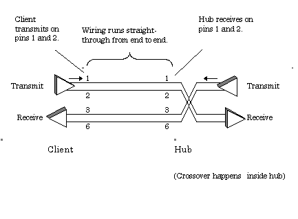
The use of straight-through wiring simplifies installation and maintenance considerably. It eliminates any concern about whether a link might have a crossover at one end, the other, or both.
Certain exception conditions exist, like the connection between two hub ports. In this case both pieces of equipment may already include an internal crossover. The installer is expected to provide an external crossover (that is, a crossover explicitly implemented in the wiring).
When necessary, an external crossover should be implemented in a short, clearly visible section of cabling and boldly labeled.
Examples of crossover connections appropriate for Fast Ethernet (100BASE-TX) appear in Table 7.3 and Table 7.4
Table 7.3. Wiring Crossover for 100- W Balanced Cables
|
Pair 3 |
Pair 2 |
Pair 1 |
Pair 4 |
|||||
|---|---|---|---|---|---|---|---|---|
|
From pin: [1] |
1 |
2 |
3 |
6 |
4 |
5 |
7 |
8 |
|
To pin: [1] |
3 |
6 |
1 |
2 |
7 |
8 |
4 |
5 |
 2
2[2] NOTE (2) ”RJ-45 pin numbers .
[1] NOTE (1) ”Not used by 100BASE-TX.
Table 7.4. Wiring Crossover for 150- W STP-A; References Are to DB-9 Pin Numbers
|
Pair 1 |
Pair 2 |
Other Pins Not Used |
|||
|---|---|---|---|---|---|
|
From pin: [1] |
5 |
9 |
1 |
6 |
2,3,4,7,8 |
|
To pin: [1] |
1 |
6 |
5 |
9 |
|
[1] NOTE (1) ”DB-9 pin numbers.
POINTS TO REMEMBER
- Multi-pair building cables should be installed straight-through with no crossing of the pairs.
- When necessary, an external crossover should be implemented in a short, clearly visible section of cabling and boldly labeled.
Fundamentals
- Impedance of Linear, Time-Invariant, Lumped-Element Circuits
- Power Ratios
- Rules of Scaling
- The Concept of Resonance
- Extra for Experts: Maximal Linear System Response to a Digital Input
Transmission Line Parameters
- Transmission Line Parameters
- Telegraphers Equations
- Derivation of Telegraphers Equations
- Ideal Transmission Line
- DC Resistance
- DC Conductance
- Skin Effect
- Skin-Effect Inductance
- Modeling Internal Impedance
- Concentric-Ring Skin-Effect Model
- Proximity Effect
- Surface Roughness
- Dielectric Effects
- Impedance in Series with the Return Path
- Slow-Wave Mode On-Chip
Performance Regions
- Performance Regions
- Signal Propagation Model
- Hierarchy of Regions
- Necessary Mathematics: Input Impedance and Transfer Function
- Lumped-Element Region
- RC Region
- LC Region (Constant-Loss Region)
- Skin-Effect Region
- Dielectric Loss Region
- Waveguide Dispersion Region
- Summary of Breakpoints Between Regions
- Equivalence Principle for Transmission Media
- Scaling Copper Transmission Media
- Scaling Multimode Fiber-Optic Cables
- Linear Equalization: Long Backplane Trace Example
- Adaptive Equalization: Accelerant Networks Transceiver
Frequency-Domain Modeling
- Frequency-Domain Modeling
- Going Nonlinear
- Approximations to the Fourier Transform
- Discrete Time Mapping
- Other Limitations of the FFT
- Normalizing the Output of an FFT Routine
- Useful Fourier Transform-Pairs
- Effect of Inadequate Sampling Rate
- Implementation of Frequency-Domain Simulation
- Embellishments
- Checking the Output of Your FFT Routine
Pcb (printed-circuit board) Traces
- Pcb (printed-circuit board) Traces
- Pcb Signal Propagation
- Limits to Attainable Distance
- Pcb Noise and Interference
- Pcb Connectors
- Modeling Vias
- The Future of On-Chip Interconnections
Differential Signaling
- Differential Signaling
- Single-Ended Circuits
- Two-Wire Circuits
- Differential Signaling
- Differential and Common-Mode Voltages and Currents
- Differential and Common-Mode Velocity
- Common-Mode Balance
- Common-Mode Range
- Differential to Common-Mode Conversion
- Differential Impedance
- Pcb Configurations
- Pcb Applications
- Intercabinet Applications
- LVDS Signaling
Generic Building-Cabling Standards
- Generic Building-Cabling Standards
- Generic Cabling Architecture
- SNR Budgeting
- Glossary of Cabling Terms
- Preferred Cable Combinations
- FAQ: Building-Cabling Practices
- Crossover Wiring
- Plenum-Rated Cables
- Laying Cables in an Uncooled Attic Space
- FAQ: Older Cable Types
100-Ohm Balanced Twisted-Pair Cabling
- 100-Ohm Balanced Twisted-Pair Cabling
- UTP Signal Propagation
- UTP Transmission Example: 10BASE-T
- UTP Noise and Interference
- UTP Connectors
- Issues with Screening
- Category-3 UTP at Elevated Temperature
150-Ohm STP-A Cabling
- 150-Ohm STP-A Cabling
- 150- W STP-A Signal Propagation
- 150- W STP-A Noise and Interference
- 150- W STP-A: Skew
- 150- W STP-A: Radiation and Safety
- 150- W STP-A: Comparison with UTP
- 150- W STP-A Connectors
Coaxial Cabling
- Coaxial Cabling
- Coaxial Signal Propagation
- Coaxial Cable Noise and Interference
- Coaxial Cable Connectors
Fiber-Optic Cabling
- Fiber-Optic Cabling
- Making Glass Fiber
- Finished Core Specifications
- Cabling the Fiber
- Wavelengths of Operation
- Multimode Glass Fiber-Optic Cabling
- Single-Mode Fiber-Optic Cabling
Clock Distribution
- Clock Distribution
- Extra Fries, Please
- Arithmetic of Clock Skew
- Clock Repeaters
- Stripline vs. Microstrip Delay
- Importance of Terminating Clock Lines
- Effect of Clock Receiver Thresholds
- Effect of Split Termination
- Intentional Delay Adjustments
- Driving Multiple Loads with Source Termination
- Daisy-Chain Clock Distribution
- The Jitters
- Power Supply Filtering for Clock Sources, Repeaters, and PLL Circuits
- Intentional Clock Modulation
- Reduced-Voltage Signaling
- Controlling Crosstalk on Clock Lines
- Reducing Emissions
Time-Domain Simulation Tools and Methods
- Ringing in a New Era
- Signal Integrity Simulation Process
- The Underlying Simulation Engine
- IBIS (I/O Buffer Information Specification)
- IBIS: History and Future Direction
- IBIS: Issues with Interpolation
- IBIS: Issues with SSO Noise
- Nature of EMC Work
- Power and Ground Resonance
Points to Remember
Appendix A. Building a Signal Integrity Department
Appendix B. Calculation of Loss Slope
Appendix C. Two-Port Analysis
- Appendix C. Two-Port Analysis
- Simple Cases Involving Transmission Lines
- Fully Configured Transmission Line
- Complicated Configurations
Appendix D. Accuracy of Pi Model
Appendix E. erf( )
Notes
EAN: N/A
Pages: 163
