THE DFT OF RECTANGULAR FUNCTIONS
We conclude this chapter by providing the mathematical details of two important aspects of the DFT. First, we obtain the expressions for the DFT of a rectangular function (rectangular window), and then we'll use these results to illustrate the magnitude response of the DFT. We're interested in the DFT's magnitude response because it provides an alternate viewpoint to understand the leakage that occurs when we use the DFT as a signal analysis tool.
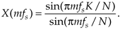
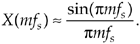
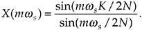
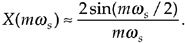
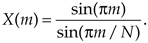
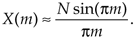
One of the most prevalent and important computations encountered in digital signal processing is the DFT of a rectangular function. We see it in sampling theory, window functions, discussions of convolution, spectral analysis, and in the design of digital filters. As common as it is, however, the literature covering the DFT of rectangular functions can be confusing for several reasons for the digital signal processing beginner. The standard mathematical notation is a bit hard to follow at first, and sometimes the equations are presented with too little explanation. Compounding the problem, for the beginner, are the various expressions of this particular DFT. In the literature, we're likely to find any one of the following forms for the DFT of a rectangular function:
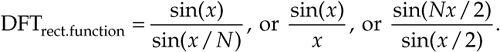
In this section we'll show how the forms in Eq. (3-34) were obtained, see how they're related, and create a kind of Rosetta stone table allowing us to move back and forth between the various DFT expressions. Take a deep breath and let's begin our discussion with the definition of a rectangular function.
3.13.1 DFT of a General Rectangular Function
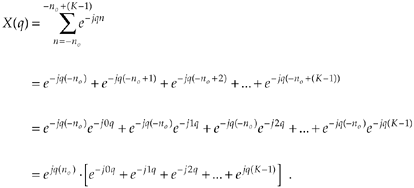
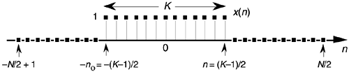
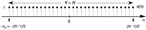
A general rectangular function x(n) can be defined as N samples containing K unity-valued samples as shown in Figure 3-24. The full N-point sequence, x(n), is the rectangular function that we want to transform. We call this the general form of a rectangular function because the K unity samples begin at a arbitrary index value of –no. Let's take the DFT of x(n) in Figure 3-24 to get our desired X(m). Using m as our frequency-domain sample index, the expression for an N-point DFT is
Equation 3-35
Figure 3-24. Rectangular function of width K samples defined over N samples where K < N.
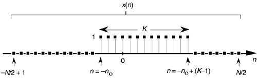
With x(n) being nonzero only over the range of –no  n –no + (K–1), we can modify the summation limits of Eq. (3-35) to express X(m) as
Equation 3-36
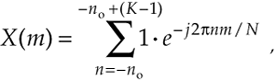
because only the K samples contribute to X(m). That last step is important because it allows us to eliminate the x(n) terms and make Eq. (3-36) easier to handle. To keep the following equations from being too messy, let's use the dummy variable q = 2pm/N.
OK, here's where the algebra comes in. Over our new limits of summation, we eliminate the factor of 1 and Eq. (3-36) becomes
Equation 3-37
The series inside the brackets of Eq. (3-37) allows the use of a summation, such as
Equation 3-38
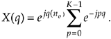
Equation (3-38) certainly doesn't look any simpler than Eq. (3-36), but it is. Equation (3-38) is a geometric series and, from the discussion in Appendix B, it can be evaluated to the closed form of
Equation 3-39
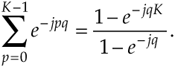
We can now simplify Eq. (3-39)—here's the clever step. If we multiply and divide the numerator and denominator of Eq. (3-39)'s right-hand side by the appropriate half-angled exponentials, we break the exponentials into two parts and get
Equation 3-40
Let's pause for a moment here to remind ourselves where we're going. We're trying to get Eq. (3-40) into a usable form because it's part of Eq. (3-38) that we're using to evaluate X(m) in Eq. (3-36) in our quest for an understandable expression for the DFT of a rectangular function.
Equation (3-40) looks even more complicated than Eq. (3-39), but things can be simplified inside the parentheses. From Euler's equation: sin(ø) = (ejø – e–jø)/2j, Eq. (3-40) becomes
Equation 3-41
Substituting Eq. (3-41) for the summation in Eq. (3-38), our expression for X(q) becomes
Equation 3-42
Returning our dummy variable q to its original value of 2pm/N,
Equation 3-43
So there it is (Whew!). Equation (3-43) is the general expression for the DFT of the rectangular function as shown in Figure 3-24. Our X(m) is a complex expression (pun intended) where a ratio of sine terms is the amplitude of X(m) and the exponential term is the phase angle of X(m).[ ] The ratio of sines factor in Eq. (3-43) lies on the periodic curve shown in Figure 3-25(a), and like all N-point DFT representations, the periodicity of X(m) is N. This curve is known as the Dirichlet kernel (or the aliased sinc function) and has been thoroughly described in the literature[10,13,14]. (It's named after the nineteenth-century German mathematician Peter Dirichlet (pronounced dee-ree-klay'), who studied the convergence of trigonometric series used to represent arbitrary functions.)
[
Figure 3-25. The Dirichlet kernel of X(m): (a) periodic continuous curve on which the X(m) samples lie; (b) X(m) amplitudes about the m = 0 sample; (c) |X(m)| magnitudes about the m = 0 sample.
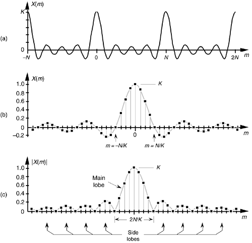
We can zoom in on the curve at the m = 0 point and see more detail in Figure 3-25(b). The dots are shown in Figure 3-25(b) to remind us that the DFT of our rectangular function results in discrete amplitude values that lie on the curve. So when we perform DFTs, our discrete results are sampled values of the continuous sinc function's curve in Figure 3-25(a). As we'll show later, we're primarily interested in the absolute value, or magnitude, of the Dirichlet kernel in Eq. (3-43). That magnitude |X(m)| is shown in Figure 3-25(c). Although we first saw the sinc function's curve in Figure 3-9 in Section 3.8, where we introduced the topic of DFT leakage, we'll encounter this curve often in our study of digital signal processing.
For now, there are just a few things we need to keep in mind concerning the Dirichlet kernel. First, the DFT of a rectangular function has a main lobe, centered about the m = 0 point. The peak amplitude of the main lobe is K. This peak value makes sense, right? The m = 0 sample of a DFT X(0) is the sum of the original samples, and the sum of K unity-valued samples is K. We can show this in a more substantial way by evaluating Eq. (3-43) for m = 0. A difficulty arises when we plug m = 0 into Eq. (3-43) because we end up with sin(0)/sin(0), which is the indeterminate ratio 0/0. Well, hardcore mathematics to the rescue here. We can use L'Hopital's rule to take the derivative of the numerator and the denominator of Eq. (3-43), and then set m = 0 to determine the peak value of the magnitude of the Dirichlet kernel.[] We proceed as
[
-p
-t
l, like baby doll.
Equation 3-44
which is what we set out to show. (We could have been clever and evaluated Eq. (3-35) with m = 0 to get the result of Eq. (3-44). Try it, and keep in mind that ej0 = 1.) Had the amplitudes of the nonzero samples of x(n) been different than unity, say some amplitude Ao, then, of course, the peak value of the Dirichlet kernel would be AoK instead of just K. The next important thing to notice about the Dirichlet kernel is the main lobe's width. The first zero crossing of Eq. (3-43) occurs when the numerator's argument is equal to p. That is, when pmK/N = p. So the value of m at the first zero crossing is given by
Equation 3-45
as shown in Figure 3-25(b). Thus the main lobe width 2N/K, as shown in Figure 3-25(c), is inversely proportional to K.[]
[
Notice that the main lobe in Figure 3-25(a) is surrounded by a series of oscillations, called sidelobes, as in Figure 3-25(c). These sidelobe magnitudes decrease the farther they're separated from the main lobe. However, no matter how far we look away from the main lobe, these sidelobes never reach zero magnitude—and they cause a great deal of heartache for practitioners in digital signal processing. These sidelobes cause high-amplitude signals to overwhelm and hide neighboring low-amplitude signals in spectral analysis, and they complicate the design of digital filters. As we'll see in Chapter 5, the unwanted ripple in the passband and the poor stopband attenuation in simple digital filters are caused by the rectangular function's DFT sidelobes. (The development, analysis, and application of window functions came about to minimize the ill effects of those sidelobes in Figure 3-25.)
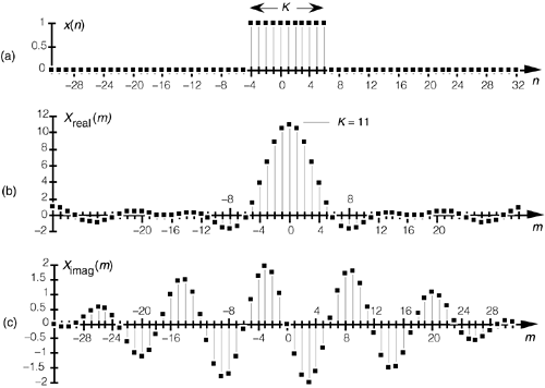
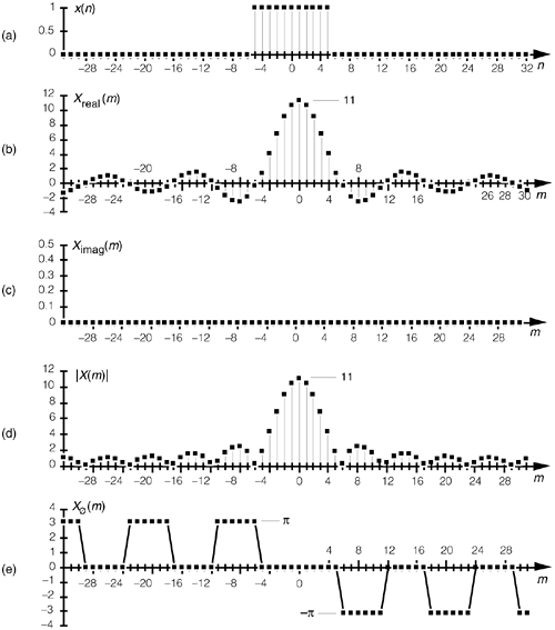
Let's demonstrate the relationship in Eq. (3-45) by way of a simple but concrete example. Assume that we're taking a 64-point DFT of the 64-sample rectangular function, with eleven unity values, shown in Figure 3-26(a). In this example, N = 64 and K = 11. Taking the 64-point DFT of the sequence in Figure 3-26(a) results in an X(m) whose real and imaginary parts, Xreal(m) and Ximag(m), are shown in Figure 3-26(b) and Figure 3-26(c) respectively. Figure 3-26(b) is a good illustration of how the real part of the DFT of a real input sequence has even symmetry, and Figure 3-26(c) confirms that the imaginary part of the DFT of a real input sequence has odd symmetry.
Figure 3-26. DFT of a rectangular function: (a) original function x(n) ; (b) real part of the DFT of x(n), Xreal(m); (c) imaginary part of the DFT of x(n), Ximag(m).
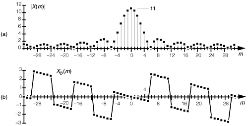
Although Xreal(m) and Ximag(m) tell us everything there is to know about the DFT of x(n), it's a bit easier to comprehend the true spectral nature of X(m) by viewing its absolute magnitude. This magnitude, from Eq. (3-7), is provided in Figure 3-27(a) where the main and sidelobes are clearly evident now. As we expected, the peak value of the main lobe is 11 because we had K = 11 samples in x(n). The width of the main lobe from Eq. (3-45) is 64/11, or 5.82. Thus, the first positive frequency zero-crossing location lies just below the m = 6 sample of our discrete |X(m)| represented by the squares in Figure 3-27(a). The phase angles associated with |X(m)|, first introduced in Equations (3-6) and (3-8), are shown in Figure 3-27(b).
Figure 3-27. DFT of a generalized rectangular function: (a) magnitude |X(m)|; (b) phase angle in radians.
To understand the nature of the DFT of rectangular functions more fully, let's discuss a few more examples using less general rectangular functions that are more common in digital signal processing than the x(n) in Figure 3-24.
3.13.2 DFT of a Symmetrical Rectangular Function
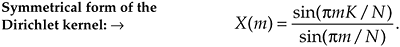
Equation (3-43) is a bit complicated because our original function x(n) was so general. In practice, special cases of rectangular functions lead to simpler versions of Eq. (3-43). Consider the symmetrical x(n) rectangular function in Figure 3-28. As shown in Figure 3-28, we often need to determine the DFT of a rectangular function that's centered about the n = 0 index point. In this case, the K unity-valued samples begin at n = –no = –(K–1)/2. So substituting (K–1)/2 for no in Eq. (3-43) yields
Figure 3-28. Rectangular x(n) with K samples centered about n = 0.
Equation 3-46
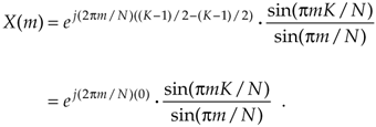
Because ej0 = 1, Eq. (3-46) becomes
Equation 3-47
Equation (3-47) indicates that the DFT of the symmetrical rectangular function in Figure 3-28 is itself a real function; that is, there's no complex exponential in Eq. (3-47), so this particular DFT contains no imaginary part or phase term. As we stated in Section 3.2, if x(n) is real and even, x(n) = x(–n), then Xreal(m) is nonzero and Ximag(m) is always zero. We demonstrate this by taking the 64-point DFT of the sequence in Figure 3-29(a). Our x(n) is 11 unity-valued samples centered about the n = 0 index. Here the DFT results in an X(m) whose real and imaginary parts are shown in Figure 3-29(b) and Figure 3-29(c), respectively. As Eq. (3-47) predicted, Xreal(m) is nonzero and Ximag(m) is zero. The magnitude and phase of X(m) are depicted in Figure 3-29(d) and Figure 3-29(e).
Figure 3-29. DFT of a rectangular function centered about n = 0: (a) original x(n) ; (b) Xreal(m); (c) Ximag(m); (d) magnitude of X(m); (e) phase angle of X(m) in radians.
Notice that the magnitudes in Figure 3-27(a) and Figure 3-29(d) are identical. This verifies the very important shifting theorem of the DFT; that is, the magnitude |X(m)| depends only on the number of nonzero samples in x(n), K, and not on their position relative to the n = 0 index value. Shifting the K unity-valued samples to center them about the n = 0 index merely affects the phase angle of X(m), not its magnitude.
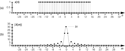
Speaking of phase angles, it's interesting to realize here that even though Ximag(m) is zero in Figure 3-29(c), the phase angle of X(m) is not always zero. In this case, X(m)'s individual phase angles in Figure 3-29(e) are either +p, zero, or –p radians. With +p and –p radians both being equal to –1, we could easily reconstruct Xreal(m) from |X(m)| and the phase angle Xø(m) if we must. Xreal(m) is equal to |X(m)| with the signs of |X(m)|'s alternate sidelobes reversed.[] To gain some further appreciation of how the DFT of a rectangular function is a sampled version of the Dirichlet kernel, let's increase the number of our nonzero x(n) samples. Figure 3-30(a) shows a 64-point x(n) where 31 unity-valued samples are centered about the n = 0 index location. The magnitude of X(m) is provided in Figure 3-30(b). By broadening the x(n) function, i.e., increasing K, we've narrowed the Dirichlet kernel of X(m). This follows from Eq. (3-45), right? The kernel's first zero crossing is inversely proportional to K, so, as we extend the width of K, we squeeze |X(m)| in toward m = 0. In this example, N = 64 and K = 31. From Eq. (3-45) the first positive zero crossing of X(m) occurs at 64/31, or just slightly to the right of the m = 2 sample in Figure 3-30(b). Also notice that the peak value of |X(m)| = K = 31, as mandated by Eq. (3-44).
[
Figure 3-30. DFT of a symmetrical rectangular function with 31 unity values: (a) original x(n); (b) magnitude of X(m).
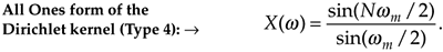
3.13.3 DFT of an All Ones Rectangular Function
The DFT of a special form of x(n) is routinely called for, leading to yet another simplified form of Eq. (3-43). In the literature, we often encounter a rectangular function where K = N; that is, all N samples of x(n) are nonzero, as shown in Figure 3-31. In this case, the N unity-valued samples begin at n = –no = –(N–1)/2. We obtain the expression for the DFT of the function in Figure 3-31 by substituting K = N and no = (N–1)/2 in Eq. (3-43) to get
Figure 3-31. Rectangular function with N unity-valued samples.
Equation 3-48
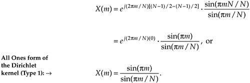
Equation (3-48) takes the first form of Eq. (3-34) that we alluded to at the beginning of Section 3.13.[] Figure 3-32 demonstrates the meaning of Eq. (3-48). The DFT magnitude of the all ones function, x(n) in Figure 3-32(a), is shown in Figure 3-32(b) and Figure 3-32(c). Take note that if m was continuous Eq. (3-48) describes the shaded curves in Figure 3-32(b) and Figure 3-32(c). If m is restricted to be integers, then Eq. (3-48) represents the dots in those figures.
[] By the way, there's nothing official about calling Eq. (3-48) a Type 1 Dirichlet kernel. We're using the phrase Type 1 merely to distinguish Eq. (3-48) from other mathematical expressions for the Dirichlet kernel that we're about to encounter.
Figure 3-32. All ones function: (a) rectangular function with N = 64 unity-valued samples; (b) DFT magnitude of the all ones time function; (c) close-up view of the DFT magnitude of an all ones time function.
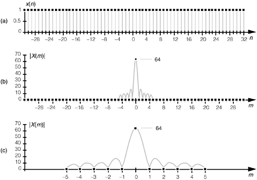
The Dirichlet kernel of X(m) in Figure 3-32(b) is now as narrow as it can get. The main lobe's first positive zero crossing occurs at the m = 64/64 = 1 sample in Figure 3-32(b) and the peak value of |X(m)| = N = 64. With x(n) being all ones, |X(m)| is zero for all m  0. The sinc function in Eq. (3-48) is of utmost importance—as we'll see at the end of this chapter, it defines the overall DFT frequency response to an input sinusoidal sequence, and it's also the amplitude response of a single DFT bin.
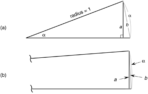
The form of Eq. (3-48) allows us to go one step further to identify the most common expression for the DFT of an all ones rectangular function found in the literature. To do this, we have to use an approximation principle found in the mathematics of trigonometry that you may have heard before. It states that when a is small, then sin(a) is approximately equal to a, i.e., sin(a)  a. This idea comes about when we consider a pie-shaped section of a circle whose radius is 1 as shown in Figure 3-33(a). That section is defined by the length of the arc a measured in radians and a's chord b. If we draw a right triangle inside the section, we can say that a = sin(a). As a gets smaller the long sides of our triangle become almost parallel, the length of chord b approaches the length of arc a, and the length of line a approaches the length of b. So, as depicted in Figure 3-33(b), when a is small, a b a = sin(a). We use this sin(a) a approximation when we look at the denominator of Eq. (3-48). When pm/N is small, then sin(pm/N) is approximately equal to pm/N. So we can, when N is large, state
Figure 3-33. Relationships between an angle a, line a = sin(a), and a's chord b: (a) large angle a; (b) small angle a.
Equation 3-49
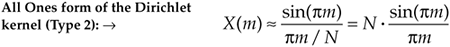
It has been shown that when N is larger than, say, 10 in Eq. (3-48), Eq. (3-49) accurately describes the DFT's output.[] Equation (3-49) is often normalized by dividing it by N, so we can express the normalized DFT of an all ones rectangular function as
[
Equation 3-50
Equation (3-50), taking the second form of Eq. (3-34) that is so often seen in the literature, also has the DFT magnitude shown in Figure 3-32(b) and Figure 3-32(c).
3.13.4 Time and Frequency Axes Associated with Rectangular Functions
Let's establish the physical dimensions associated with the n and m index values. So far in our discussion, the n index was merely an integer enabling us to keep track of individual x(n) sample values. If the n index represents instants in time, we can identify the time period separating adjacent x(n) samples to establish the time scale for the x(n) axis and the frequency scale for the X(m) axis. Consider the time-domain rectangular function given in Figure 3-34(a). That function comprises N time samples obtained ts seconds apart, and the full sample interval is Nts seconds. Each x(n) sample occurs at nts seconds for some value of n. For example, the n = 9 sample value, x(9) = 0, occurs at 9ts seconds.
Figure 3-34. DFT time and frequency axis dimensions: (a) time-domain axis uses time index n; (b) various representations of the DFT's frequency axis.
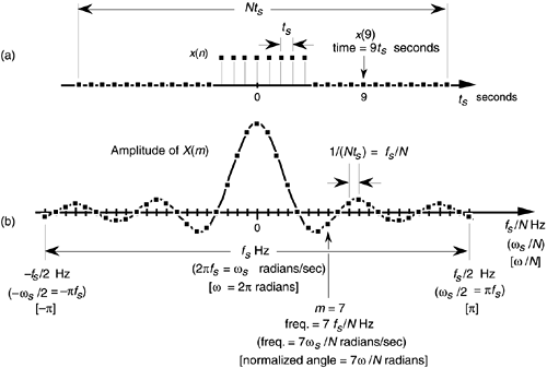
The frequency axis of X(m) can be represented in a number of different ways. Three popular types of DFT frequency axis labeling are shown in Figure 3-34(b) and listed in Table 3-1. Let's consider each representation individually.
3.13.4.1 DFT Frequency Axis in Hz
If we decide to relate X(m) to the time sample period ts, or the sample rate fs = 1/ts, then the frequency axis variable is m/Nts = mfs/N. So each X(m) sample is associated with a cyclic frequency of mfs/N Hz. In this case, the resolution of X(m) is fs/N. The DFT repetition period, or periodicity, is fs Hz, as shown in Figure 3-34(b). If we substitute the cyclic frequency variable mfs/N for the generic variable of m/N in Eq. (3-47), we obtain an expression for the DFT of a symmetrical rectangular function, where K < N, in terms of the sample rate fs in Hz. That expression is
Table 3-1. Characteristics of Various DFT Frequency Axis Representations
|
DFT Frequency Axis Representation |
X(m) Frequency Variable |
Resolution of X(m) |
Repetition Interval of X(m) |
Frequency Axis Range |
|---|---|---|---|---|
|
Frequency in Hz |
mfs/N |
fs/N |
fs |
–fs/2 to fs/2 |
|
Frequency in radians |
mws/N or 2pmfs/N |
ws/N or 2pfs/N |
ws or 2pfs |
–ws/2 to ws/2 or –pfs to pfs |
|
Normalized angle in radians |
2pm/N |
2p/N |
2p |
–p to p |
Equation 3-51
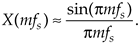
For an all ones rectangular function where K = N, the amplitude normalized sin(x)/x approximation in Eq. (3-50) can be rewritten in terms of sample rate fs in Hz as
Equation 3-52
3.13.4.2 DFT Frequency Axis in Radians/Second
We can measure X(m)'s frequency in radians/s by defining the time-domain sample rate in radians/s as ws = 2pfs. So each X(m) sample is associated with a radian frequency of mws/N = 2pmfs/N radians/s. In this case, X(m)'s resolution is ws/N = 2pfs/N radians/s, and the DFT repetition period is ws = 2pfs radians/s, as shown by the expressions in parentheses in Figure 3-34(b). With ws = 2pfs, then pfs = ws/2. If we substitute ws/2 for pfs in Eq. (3-51), we obtain an expression for the DFT of a symmetrical rectangular function, where K < N, in terms of the sample rate ws in radians/s:
Equation 3-53
For an all ones rectangular function where K = N, the amplitude normalized sin(x)/x approximation in Eq. (3-50) can be stated in terms of a sample rate ws in radians/s as
Equation 3-54
3.13.4.3 DFT Frequency Axis Using a Normalized Angle Variable
Many authors simplify the notation of their equations by using a normalized variable for the radian frequency ws = 2pfs. By normalized, we mean that the sample rate fs is assumed to be equal to 1, and this establishes a normalized radian frequency ws equal to 2p. Thus, the frequency axis of X(m) now becomes a normalized angle w, and each X(m) sample is associated with an angle of mw/N radians. Using this convention, X(m)'s resolution is w/N radians, and the DFT repetition period is w= 2p radians, as shown by the expressions in brackets in Figure 3-34(b).
Unfortunately the usage of these three different representations of the DFT's frequency axis is sometimes confusing for the beginner. When reviewing the literature, the reader can learn to convert between these frequency axis notations by consulting Figure 3-34 and Table 3-1.
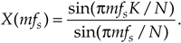
3.13.5 Alternate Form of the DFT of an All Ones Rectangular Function
Using the normalized radian angle notation for the DFT axis from the bottom row of Table 3-1 leads to another prevalent form of the DFT of the all ones rectangular function in Figure 3-31. Letting our normalized discrete frequency axis variable be wm = 2pm/N, then pm = Nwm/2. Substituting the term Nwm/2 for pm in Eq. (3-48), we obtain
Equation 3-55
Equation (3-55), taking the third form of Eq. (3-34) sometimes seen in the literature, also has the DFT magnitude shown in Figure 3-32(b) and Figure 3-32(c).
We've covered so many different expressions for the DFT of various rectangular functions that it's reasonable to compile their various forms in Table 3-2.
3.13.6 Inverse DFT of a General Rectangular Function
Let's think now about computing the inverse DFT of a rectangular frequency-domain function; that is, given a rectangular X(m) function, find a time- domain function x(n). We can define the general form of a rectangular frequency-domain function, as we did for Figure 3-24, to be that shown in Figure 3-35. The inverse DFT of the rectangular function X(m) in Figure 3-35 is
Equation 3-56
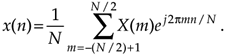
Figure 3-35. General rectangular frequency-domain function of width K samples defined over N samples where K < N.
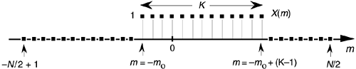
The same algebraic acrobatics we used to arrive at Eq. (3-43) can be applied to Eq. (3-56), guiding us to
Equation 3-57
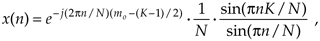
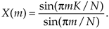
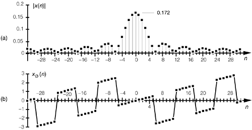
for the inverse DFT of the rectangular function in Figure 3-35. The descriptions we gave for Eq. (3-43) apply equally well to Eq. (3-57) with the exception of a 1/N scale factor term and a change in the sign of Eq. (3-43)'s phase angle. Let's use Eq. (3-57) to take a 64-point inverse DFT of the 64-sample rectangular function shown in Figure 3-36(a). The inverse DFT of the sequence in Figure 3-36(a) results in an x(n) whose real and imaginary parts, xreal(n) and ximag(n), are shown in Figure 3-36(b) and Figure 3-36(c), respectively. With N = 64 and K = 11 in this example, we've made the inverse DFT functions in Figure 3-36 easy to compare with those forward DFT functions in Figure 3-26. See the similarity between the real parts, Xreal(m) and xreal(n), in Figure 3-26(b) and Figure 3-36(b)? Also notice the sign change between the imaginary parts in Figure 3-26(c) and Figure 3-36(c).
Figure 3-36. Inverse DFT of a general rectangular function: (a) original function X(m); (b) real part, xreal(n); (c) imaginary part, ximag(n).
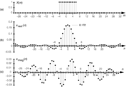
Table 3-2. DFT of Various Rectangular Functions
|
Description |
Expression |
|---|---|
|
DFT of a general rectangular function, where K < N, in terms of the integral frequency m variable |
Equation 3-46
|
|
DFT of a symmetrical rectangular function, where K < N, in terms of the integral frequency variable m |
Equation 3-47
|
|
DFT of an all ones rectangular function in terms of the integer frequency variable m (Dirichlet kernel Type 1) |
Equation 3-48
|
|
DFT of an all ones rectangular function in terms of the integer frequency variable m (Dirichlet kernel Type 2) |
Equation 3-49
|
|
Amplitude normalized DFT of an all ones rectangular function in terms of the integral frequency variable m (Dirichlet kernel Type 3) |
Equation 3-50
|
|
DFT of a symmetrical rectangular function, where K < N, in terms of the sample rate fs in Hz |
Equation 3-51
|
|
Amplitude normalized DFT of an all ones rectangular function in terms of the sample rate fs in Hz |
Equation 3-52
|
|
DFT of a symmetrical rectangular function, where K < N, in terms of the sample rate ws in radians/s |
Equation 3-53
|
|
Amplitude normalized DFT of an all ones rectangular function in terms of the sample rate ws in radians/s |
Equation 3-54
|
|
DFT of an all ones rectangular function in terms of the normalized discrete frequency variable wm (Dirichlet kernel Type 4). |
Equation 3-55
|
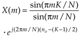
The magnitude and phase angle of x(n) are shown in Figure 3-37(a) and Figure 3-37(b). Note the differences in main lobe peak magnitude between Figure 3-27(a) and Figure 3-37(a). The peak magnitude value in Figure 3-37(a) is K/N = 11/64, or 0.172. Also notice the sign change between the phase angles in Figure 3-27(b) and Figure 3-37(b). The illustrations in Figures 3-26, 3-27, 3-36, and 3-37 are good examples of the fundamental duality relationships between the forward and inverse DFT.
Figure 3-37. Inverse DFT of a generalized rectangular function: (a) magnitude |x(n)|; (b) phase angle of x(n) in radians.
3.13.7 Inverse DFT of a Symmetrical Rectangular Function
The inverse DFT of the general rectangular function in Figure 3-36 is not very common in digital signal processing. However, in discussions concerning digital filters, we will encounter the inverse DFT of symmetrical rectangular functions. This inverse DFT process is found in the window design method of what are called low-pass finite impulse response (FIR) digital filters. That method begins with the definition of a symmetrical frequency function, H(m), such as that in Figure 3-38. The inverse DFT of the frequency samples in Figure 3-38 is then taken to determine the time-domain coefficients for use in a low-pass FIR filter. (Time-domain FIR filter coefficients are typically denoted h(n) instead of x(n), so we'll use h(n) throughout the remainder of this inverse DFT discussion.)
Figure 3-38. Frequency-domain rectangular function of width K samples defined over N samples.
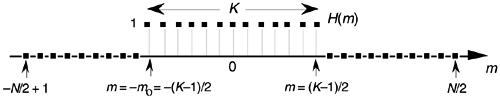
In the case of the frequency domain H(m) in Figure 3-38, the K unity- valued samples begin at m = –mo = –(K–1)/2. So plugging (K–1)/2 in for mo in Eq. (3-57) gives
Equation 3-58
Again, because ej0 = 1, Eq. (3-58) becomes
Equation 3-59
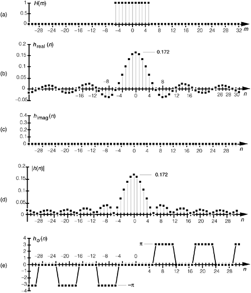
Equation (3-59) tells us that the inverse DFT of the symmetrical rectangular function in Figure 3-38 is itself a real function that we can illustrate by example. We'll perform a 64-point inverse DFT of the sequence in Figure 3-39(a). Our H(m) is 11 unity-valued samples centered about the m = 0 index. Here the inverse DFT results in an h(n) whose real and imaginary parts are shown in Figure 3-39(b) and Figure 3-39(c), respectively. As Eq. (3-47) predicted, hreal(n) is nonzero and himag(n) is zero. The magnitude and phase of h(n) are depicted in Figure 3-39(d) and Figure 3-39(e). (Again, we've made the functions in Figure 3-39 easy to compare with the forward DFT function in Figure 3-29.) It is h(n)'s real part that we're really after here. Those values of hreal(n) are used for the time-domain filter coefficients in the design of FIR low-pass filters that we'll discuss in Section 5.3.
Figure 3-39. Inverse DFT of a rectangular function centered about m = 0: (a) original H(m); (b) hreal(n); (c) himag(n); (d) magnitude of h(n); (e) phase of h(n) in radians.
URL http://proquest.safaribooksonline.com/0131089897/ch03lev1sec13
| Amazon | ||
