HIGH-SPEED VECTOR MAGNITUDE APPROXIMATION
The quadrature processing techniques employed in spectrum analysis, computer graphics, and digital communications routinely require high speed determination of the magnitude of a complex number (vector V) given its real and imaginary parts, i.e., the in-phase part I and the quadrature-phase part Q. This magnitude calculation requires a square root operation because the magnitude of V is
Assuming that the sum I2 + Q2 is available, the problem is efficiently to perform the square root operation.
There are several ways to obtain square roots. The optimum technique depends on the capabilities of the available hardware and software. For example, when performing a square root using a high-level software language, we employ whatever software square root function is available. Although accurate, software routines can be very slow. By contrast, if a system must accomplish a square root operation in 50 nanoseconds, high-speed magnitude approximations are required[4,5]. Let's look at a neat magnitude approximation scheme that's particularly hardware efficient.
There is a technique called the aMax+bMin (read as "alpha max plus beta min") algorithm for calculating the magnitude of a complex vector.[ ] It's a linear approximation to the vector magnitude problem that requires the determination of which orthogonal vector, I or Q, has the greater absolute value. If the maximum absolute value of I or Q is designated by Max, and the minimum absolute value of either I or Q is Min, an approximation of |V| using the aMax+bMin algorithm is expressed as
[
Equation 13-6
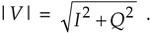
There are several pairs for the a and b constants that provide varying degrees of vector magnitude approximation accuracy to within 0.1 dB[4,7]. The aMax+bMin algorithms in Reference [10] determine a vector magnitude at whatever speed it takes a system to perform a magnitude comparison, two multiplications, and one addition. But those algorithms require, as a minimum, a 16-bit multiplier to achieve reasonably accurate results. If, however, hardware multipliers are not available, all is not lost. By restricting the a and b constants to reciprocals of integer powers of two, Eq. (13-6) lends itself well to implementation in binary integer arithmetic. A prevailing application of the aMax+bMin algorithm uses a = 1.0 and b = 0.5[8–10]. The 0.5 multiplication operation is performed by shifting the minimum quadrature vector magnitude, Min, to the right by one bit. We can gauge the accuracy of any vector magnitude estimation algorithm by plotting its error as a function of vector phase angle. Let's do that. The aMax+bMin estimate for a complex vector of unity magnitude, using
Equation 13-7
over the vector angular range of 0 to 90 degrees, is shown as the solid curve in Figure 13-7. (The curves in Figure 13-7 repeat every 90°.)
Figure 13-7. Normalized aMax+bMin estimates for a = 1; and b = 1/2, 1/4, and 3/8.
An ideal estimation curve for a unity magnitude vector would have a value of one. We'll use this ideal estimation curve as a yardstick to measure the merit of various aMax+bMin algorithms. Let's make sure we know what the solid curve in Figure 13-7 is telling us. It indicates that a unity magnitude vector oriented at an angle of approximately 26° will be estimated by Eq. (13-7) to have a magnitude of 1.118 instead of the correct magnitude of one. The error then, at 26°, is 11.8%, or 0.97 dB. Analyzing the entire solid curve in Figure 13-7 results in an average error, over the 0 to 90° range, of 8.6% (0.71 dB). Figure 13-7 also presents the error curves for the a = 1 and b = 1/4, and the a = 1 and b = 3/8 values.
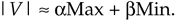
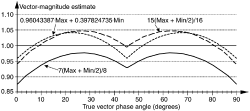
Although the values for a and b in Figure 13-7 yield rather accurate vector magnitude estimates, there are other values for a and b that deserve our attention because they result in smaller error standard deviations. Consider the a = 7/8 and b = 7/16 pair where its error curve is the solid curve in Figure 13-8. A further improvement can be obtained using a = 15/16 and b = 15/32 having an error shown by the dashed curve in Figure 13-8. The a = 15/16 and b = 15/32 pair give rather good results when compared to the optimum floating point values of a = 0.96043387 and b = 0.397824735 reported in Reference [11], whose error is the dotted curve in Figure 13-8.
Figure 13-8. aMax+bMin estimates for a = 7/8, b = 7/16; a = 15/16, b = 15/32; and a = 0.96043387, b = 0.397824735.
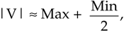
Although using b = 15/16 and b = 15/32 appears to require two multiplications and one addition, its digital hardware implementation can be straightforward, as shown in Figure 13-9. The diagonal lines, 1 for example, denote a hardwired shift of one bit to the right to implement a divide-by-two operation by truncation. Likewise, the 4 symbol indicates a right shift by four bits to realize a divide-by-16 operation. The |I|>|Q| control line is TRUE when the magnitude of I is greater than the magnitude of Q, so that Max = |I| and Min = |Q|. This condition enables the registers to apply the values |I| and |Q|/2 to the adder. When |I| > |Q| is FALSE, the registers apply the values |Q| and |I|/2 to the adder. Notice that the output of the adder, Max + Min/2, is the result of Eq. (13-26). Equation (13-29) is implemented via the subtraction of (Max + Min/2)/16 from Max + Min/2.
Figure 13-9. Hardware implementation using a = 15/16 and b = 15/32.
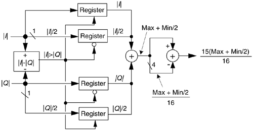
In Figure 13-9, all implied multiplications are performed by hardwired bit shifting and the total execution time is limited only by the delay times associated with the hardware components.
One thing to keep in mind. Because the various |V| estimations can exceed the correct normalized vector magnitude value, i.e., some magnitude estimates are greater than one. This means that although the correct magnitude value may be within the system's full-scale word width, an algorithm result may exceed the word width of the system and cause overflow errors. With aMax+bMin algorithms the user must be certain that no true vector magnitude exceeds the value that will produce an estimated magnitude greater than the maximum allowable word width.
The penalty we pay for the convenience of having a and b as powers of two is the error induced by the division-by-truncation process, and we haven't taken that error into account thus far. The error curves in Figure 13-7 and Figure 13-8 were obtained using a software simulation with its floating point accuracy, and are useful in evaluating different a and b values. However, the true error introduced by the aMax+bMin algorithm will be somewhat different, due to division errors when truncation is used with finite word widths. For aMax+bMin schemes, the truncation errors are a function of the data's word width, the algorithm used, the values of both |I| and |Q|, and the vector's phase angle. (These errors due to truncation compound the errors already inherent in our aMax+bMin algorithms.) However, modeling has shown that for an 8-bit system (maximum vector magnitude = 255) the truncation error is less than 1%. As the system word width increases the truncation errors approach 0%, this means that truncation errors add very little to the inherent aMax+bMin algorithm errors.
The relative performance of the various algorithms is summarized in Table 13-2.
The last column in Table 13-2 illustrates the maximum allowable true vector magnitude as a function of the system's full-scale (F.S.) word width to avoid overflow errors.
So, the aMax+bMin algorithm enables high speed vector magnitude computation without the need for math coprocessor or hardware multiplier chips. Of course, with the recent availability of high-speed floating point multiplier integrated circuits—with their ability to multiply in one or two clock cycles—a and b may not always need to be restricted to reciprocals of integer powers of two. It's also worth mentioning that this algorithm can be nicely implemented in a single hardware integrated circuit (for example, a field programmable gate array) affording high speed operation.
Table 13-2. aMax+bMin Algorithm Comparisons
|
Algorithm |V| |
Largest error (%) |
Largest error (dB) |
Average error (%) |
Average error (dB) |
Max |V| (% F.S.) |
|---|---|---|---|---|---|
|
Max + Min/2 |
11.8% |
0.97 dB |
8.6% |
0.71 dB |
89.4% |
|
Max + Min/4 |
–11.6% |
–1.07 dB |
–0.64% |
–0.06 dB |
97.0% |
|
Max + 3Min/8 |
6.8% |
0.57 dB |
3.97% |
0.34 dB |
93.6% |
|
7(Max + Min/2)/8 |
–12.5% |
–1.16 dB |
–4.99% |
–0.45 dB |
100% |
|
15(Max + Min/2)/16 |
–6.25% |
–0.56 dB |
1.79% |
0.15 dB |
95.4% |

URL http://proquest.safaribooksonline.com/0131089897/ch13lev1sec2
| Amazon | ||
