DESIGNING VERY HIGH-ORDER FIR FILTERS
There are linear phase filtering applications wherein we're interested in designing very high performance (very narrow passband widths, and/or very high attenuation) nonrecursive FIR filters. Consider the possibility that you've used Eq. (7-39), or some other algorithm, to determine that you need to implement a 2000-tap linear phase FIR filter. Then when you try to design such a filter using your trusty Remez-Exchange-based (Parks-McClellan) filter design software, you obtain unusable design results. It happens that some software incarnations of the Remez-Exchange algorithm have convergence problems (inaccurate results) when the number of filter taps, or filter order, exceeds four to five hundred. There's a slick way around this high-order FIR filter design problem using a frequency-domain zero stuffing technique.[ ]
]
[
] I thank my DSP pal Eric Jacobsen, Minister of Algorithms at Intel Corp., for publicizing this technique.
If our FIR filter design software cannot generate FIR coefficient sets whose lengths are in the thousands, then we can design a shorter length set of coefficients and interpolate those coefficients (time-domain impulse response) to whatever length we desire. Rather than use time-domain interpolation schemes and account for their inaccuracies, we can simplify the process by performing time-domain interpolation by means of frequency-domain zero stuffing.
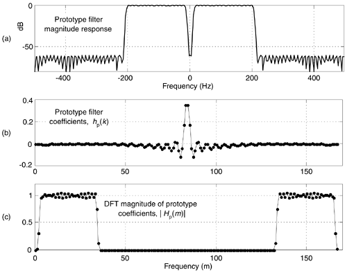
An example of the process is as follows: assume that we have a signal sampled at a rate of fs = 1000 Hz. We want a lowpass filter whose cutoff frequency is 20 Hz with 60 dB of stopband attenuation. Compounding the problem are the requirements for linear phase and removal of any DC (zero Hz) component from the signal. (Those last two requirements preclude using the DC-removal schemes in Section 13.23.) First, we design a prototype nonrecursive FIR filter having, say, N = 168 coefficients whose desired frequency response magnitude is shown in Figure 13-72(a), its hp(k) coefficients are depicted in Figure 13-72(b). Next, we compute a 168-point DFT of the coefficients to obtain the frequency-domain samples Hp(m) whose magnitudes are shown in Figure 13-72(c).
Figure 13-72. Prototype FIR filter: (a) magnitude response; (b) hp(k) coefficients; (c) |Hp(m)| magnitudes of the 168-point DFT of hp(k).

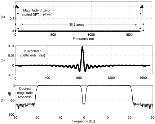
Under the assumption that our final desired filter required roughly 1600 taps, we'll interpolate the hp(k) prototype impulse response by a factor of M = 10. We perform the interpolation by inserting (M–1)N zeros in the center of the Hp(m) frequency-domain samples, yielding a 1680-point H(m) frequency-domain sequence whose magnitudes are shown in Figure 13-73(a). Finally, we perform a 1680-point inverse DFT on H(m) to obtain the interpolated h(k) impulse response (coefficients), shown in Figure 13-73(b), for our desired filter. (The ten-fold compression of the Hp(m) passband samples results in a ten-fold expansion of the hp(k) impulse response samples.) The frequency magnitude response of our final very high-order FIR filter, over the frequency range of –30 -to- 30 Hz, is provided in Figure 13-73(c).
Figure 13-73. Desired FIR filter: (a) magnitude of zero-stuffed Hp(m); (b) interpolated h(k) coefficients; (c) magnitude of desired frequency response.

With this process, the prototype filter's hp(k) coefficients are preserved within the interpolated filter's coefficients if the Hp(N/2) sample (fs/2) is zero. That condition ensures that H(m) exhibits conjugate symmetry and forces the h(k) coefficients to be real-only.
The design steps for this high-order filter design scheme are:
- With the desired filter requiring MN taps, set the number of prototype filter coefficients, N, to an integer value small enough so your FIR filter design software provides useable results. The integer interpolation factor M equals the number of desired taps divided by N.
- Design the N-tap prototype FIR filter accounting for the M-fold frequency compression in the final filter. (That is, cutoff frequencies for the prototype filter are M times the desired final cutoff frequencies.)
- Perform an N-point DFT on the prototype filter's hp(k) coefficients to obtain Hp(m).
- Insert M–1 zero-valued samples just before the Hp(N/2) sample of Hp(m) to obtain the new MN-point H(m) frequency response.
- Compute the MN-point inverse DFT of H(m) yielding an MN-length interpolated h(k) coefficient set. (Due to computational errors, discard the imaginary part of h(k), making it real-only.)
- Multiply h(k) by M to compensate for the 1/M amplitude loss induced by interpolation.
- Test the h(k) coefficient set to determine its actual frequency response using standard filter analysis methods. (One method: append thousands of zeros to h(k) and perform a very large FFT on the expanded sequence.)
An example application of this filter design is when you're building a high-performance lowpass polyphase filter, as discussed in Section 10.4. (The structures of the high-performance interpolated FIR and frequency sampling lowpass filters don't permit their decomposition into polyphase sub-filters for such an application.)
 |
Amazon |  |
