Elements of Assembly Language
Chapter 3 explains how to write assembly language programs. The first part describes the types and formats of statements that are accepted by MASM, the Microsoft Macro Assembler. Then follows an example of a complete assembly language program, with instructions on how to assemble, link, and execute this and other programs. The last portion of the chapter fills in details about constructs that have been illustrated in the example, laying the groundwork for programs in future chapters.
Assembly Language Statements
An assembly language source code file consists of a collection of statements. Most statements fit easily on an 80-character line, a good limit to observe so that source code can easily be printed or displayed on a monitor. However, MASM 6.1 accepts statements up to 512 characters long; these can be extended over more than one physical line using backslash () characters at the end of each line except the last.
Because assembly language programs are far from self-documenting, it is important to use an adequate number of comments. Comments can be used with any statement. A semicolon (;) begins the comment, and the comment then extends until the end of the line. An entire line is a comment if the semicolon is in column 1 or if a comment can follow working parts of a statement. In those rare cases where you use a backslash character to break a statement into multiple lines, a comment can follow the backslash.
There are three types of functional assembly language statements: instructions, directives, and macros. An instruction is translated by the assembler into one or more bytes of object code (machine code), which will be executed at run time. Each instruction corresponds to one of the operations that can be executed by the 80×86 CPU. The instruction
add eax, 158
was used as an example in Chapter 2.
A directive tells the assembler to take some action. Such an action does not result in machine instructions and often has no effect on the object code. For example, the assembler can produce a listing file showing the original source code, the object code, and other information. The directive
.NOLIST
anywhere in the source file tells the assembler to stop displaying source statements in the listing file. The object code produced is the same with or without the .NOLIST directive. (There is a .LIST directive to resume listing source statements.) These directives and many others start with a period, but others do not.
A macro is "shorthand" for a sequence of other statements, be they instructions, directives, or even other macros. The assembler expands a macro to the statements it represents and then assembles these new statements. Several macros will appear in the example program later in this chapter.
A statement that is more than just a comment almost always contains a mnemonic that identifies the purpose of the statement, and may have three other fields: name, operand, and comment. These components must be in the following order:
name mnemonic operand(s) ;comment
For example, a program might contain the statement
ZeroCount: mov ecx, 0 ; initialize count to zero
The name field always ends with a colon (:) when used with an instruction. When used with a directive, the name field has no colon. The mnemonic in a statement indicates a specific instruction, directive, or macro. Some statements have no operand, others have one, others have more. If there is more than one operand, they are separated by commas; spaces can also be added. Sometimes a single operand has several components with spaces between them, making it look like more than one operand.
In the instruction
add eax, 158
the mnemonic is add and the operands are eax and 158. The assembler recognizes add as a mnemonic for an instruction that will perform some sort of addition. The operands provide the rest of the information that the assembler needs. The first operand eax tells the assembler that the doubleword in the EAX register is to be one of the values added, and that the EAX register will be the destination of the sum. Since the second operand is a number (as opposed to another register designation or a memory designation), the assembler knows that it is the actual value to be added to the doubleword in the EAX register. The resulting object code is 05 00 00 00 9E, where 05 stands for "add the doubleword immediately following this byte in memory to the doubleword already in EAX." The assembler takes care of converting the decimal number 158 to its doubleword length 2's complement representation 0000009E. The bytes of this doubleword are actually stored backwards in the object code, a fact that we can almost always ignore.
One use for the name field is to label what will be symbolically, following assembly and linking of the program, an address in memory for an instruction. Other instructions can then easily refer to the labeled instruction. If the above add instruction needs to be repeatedly executed in a program loop, then it could be coded
addLoop: add eax, 158
The instruction can then be the destination of a jmp (jump) instruction, the assembly language version of a goto:
jmp addLoop ; repeat addition
Notice that the colon does not appear at the end of the name addLoop in the jmp instruction. High-level language loop structures like while or for are not available in machine language although they can be implemented using jmp or other instructions.
It is sometimes useful to have a line of source code consisting of just a name, for example
EndIfBlank:
Such a label might be used as the last line of code implementing an if-then-else-endif structure. This name effectively becomes a label for whatever instruction follows it, but it is convenient to implement a structure without worrying about what comes afterwards.
It is considered good coding practice to make labels descriptive. The label addLoop might help to clarify the assembly language code, identifying the first instruction of a program loop that includes an addition. Other labels, like EndIfBlank above, may parallel key words in a pseudocode design.
Names and other identifiers used in assembly language are formed from letters, digits, and special characters. The allowable special characters are underscore (_), question mark (?), dollar sign ($), and at sign (@). In this book, the special characters will be rarely used. A name may not begin with a digit. An identifier may have up to 247 characters, so that it is easy to form meaningful names. The Microsoft Macro Assembler will not allow instruction mnemonics, directive mnemonics, register designations, and other words that have a special meaning to the assembler to be used as names. Appendix C contains a list of such reserved identifiers.
The assembler will accept code that is almost impossible for a human to read. However, since your programs must also be read by other people, you should make them as readable as possible. Two things that help are good program formatting and use of lowercase letters.
Recall that assembly language statements can contain name, mnemonic, operand, and comment fields. A well-formatted program has these fields aligned as you read down the program. Always put names in column 1. Mnemonics might all start in column 12, operands might all start in column 18, and comments might all start in column 30-the particular columns are not as important as being consistent. Blank lines are allowed in an assembly language source file. Use blank lines to visually separate sections of assembly language code, just like breaking a written narrative into paragraphs.
Assembly language statements can be entered using either uppercase or lowercase letters. Normally the assembler does not distinguish between uppercase and lowercase. It can be instructed to distinguish within identifiers, but this is only needed when you are communicating with a program written in a language that is case-sensitive. Mixed-case code is easier for people to read than code written all in uppercase or lowercase. All uppercase code is especially difficult to read. One convention is to use mostly lowercase source code except for uppercase directives. This is the convention that will be followed for programs in this book.
Exercises 3.1
- Name and describe the three types of assembly language statements.
- For each combination of characters below, determine whether or not it is an allowable label (name). If not, give a reason.
(a)
repeat
(b)
exit
(c)
more
(d)
EndIf
(e)
2much
(f)
add
(g)
if
(h)
add2
(i)
EndOfProcessLoop
A Complete Example
This section presents a complete example of an assembly language program. We start with a pseudocode design for the program. It is easy to get lost in the details of assembly language, so your programming job will be much easier if you make a design first and then implement the design in assembly language code. This program will prompt for two numbers and then find and display their sum. The algorithm implemented by this program is
- prompt for the first number;
- input ASCII characters representing the first number;
- convert the characters to a 2's complement doubleword;
- store the first number in memory;
- prompt for the second number;
- input ASCII characters representing the second number;
- convert the characters to a 2's complement doubleword;
- add the first number to the second number;
- convert the sum to a string of ASCII characters;
- display a label and the characters representing the sum;
Figure 3.1 lists the complete program which implements this design. The parts are explained below.
 ; Example assembly language program -- adds two numbers
 ; Author: R. Detmer
 ; Date: revised 7/97
 .386
 .MODEL FLAT

 ExitProcess PROTO NEAR32 stdcall, dwExitCode:DWORD

 INCLUDE io.h ; header file for input/output

 cr EQU 0dh ; carriage return character
 Lf EQU 0ah ; line feed

 .STACK 4096 ; reserve 4096-byte stack

 .DATA ; reserve storage for data
 number1 DWORD ?
 number2 DWORD ?
 prompt1 BYTE "Enter first number: ", 0
 prompt2 BYTE "Enter second number: ", 0
 string BYTE 40 DUP (?)
 label1 BYTE cr, Lf, "The sum is "
 sum BYTE 11 DUP (?)
 BYTE cr, Lf, 0

 .CODE ; start of main program code
 _start:
 output prompt1 ; prompt for first number
 input string, 40 ; read ASCII characters
 atod string ; convert to integer
 mov number1, eax ; store in memory

 output prompt2 ; repeat for second number
 input string, 40
 atod string
 mov number2, eax


 mov eax, number1 ; first number to EAX
 add eax, number2 ; add second number
 dtoa sum, eax ; convert to ASCII characters
 output label1 ; output label and sum

 INVOKE ExitProcess, 0 ; exit with return code 0

 PUBLIC _start ; make entry point public

 END ; end of source code
Figure 3.1: A complete assembly language program
The example program begins with comments identifying the purpose of the program, the author, and the date the program was written. This is minimal documentation for any program; most organizations require much more. In the interest of saving space, the program documentation in this book will be relatively brief, although most lines of code will include comments.
The statements
 .386
 .MODEL FLAT
are both directives. Without the directive .386, MASM accepts only 8086/8088 instructions; with it, the assembler accepts the additional instructions that are executed by 80186, 80286, and 80386 processors. The .486 and .586 directives enable use of even more instructions, but we will not be programming with these instructions. There is also a .386P directive that allows the assembler to recognize privileged 80386 instructions; we will not use these instructions. The directive .MODEL FLAT tells the assembler to generate 32-bit code using a flat memory model. With MASM 6.1, this directive must follow the .386 directive.
The next statement
ExitProcess PROTO NEAR32 stdcall, dwExitCode:DWORD
is another directive. The PROTO directive is used to prototype a function. In this instance, the name of the function is ExitProcess, a system function used to terminate a program. It has one parameter, a doubleword symbolically called dwExitCode.
The next statement
INCLUDE io.h
is yet another directive. (In spite of the way it looks at this point, a program doesn't consist of only directives!) It instructs the assembler to copy the file IO.H into your program as the program is assembled.[1] The source file is not modified: It still contains just the INCLUDE directive, but for purposes of the assembly, the lines of IO.H are inserted at the point of the INCLUDE directive. In order to be included, this file should be in the same directory/folder as your source program when the assembler is invoked.
The file IO.H contains mostly definitions for macros that are described in Section 3.7. There are also several directives. The only statements from IO.H that you will see in your listing file are .NOLIST, .LIST, and a few comments. The .NOLIST directive, described above, suppresses listing most of the lines from IO.H. The last statement in IO.H is the directive .LIST that instructs the assembler to resume listing source statements. Another directive in IO.H tells the assembler to suppress listings of the statements into which a macro expands. This results in a shorter program listing.
The next two statements
 cr EQU 0dh ; carriage return character
 Lf EQU 0ah ; linefeed character
use the directive EQU to equate symbols to values. Following an EQU directive, the symbol can be used as a synonym for the value in subsequent source code. Using names rather than numbers can make clearer source code. In this example, cr is being equated to the hexadecimal number 0D, which is the ASCII code for a carriage return character; Lf is given the hex value 0A, the ASCII code for a linefeed character. An uppercase L has been used to avoid confusion with the number 1. Carriage return and linefeed characters are needed to move down to a new output line, and are frequently used in defining data to be displayed on a monitor or printed.
In these EQU directives the assembler recognizes the values 0dh and 0ah as hexadecimal because each has a trailing h. Numeric values in assembly language statements are in decimal unless otherwise indicated in the source code. Suffixes that indicate types of values other than hex will be introduced in Section 3.5. A hexadecimal value must start with a digit, not one of the hex digits "a" through "f" so that the assembler can distinguish it from a name.
The .STACK directive tells the assembler how many bytes to reserve for a run-time stack-4096 bytes is generous for the programs we will be writing. The stack is used primarily for procedure calls. Each macro in IO.H generates a procedure call to an associated procedure that actually does the task, and some of these procedures in turn call other procedures.
The directive .DATA starts the data segment of the program, the portion of the code where memory space for variables is reserved. In this program, the BYTE and DWORD directives are used to reserve bytes and doublewords of storage, respectively.
The directive
number1 DWORD ?
reserves a single doubleword of storage, associating the symbolic name number1 with the address 00000000 since it is the first data item. The question mark (?) indicates that this doubleword will have no designated initial value, although actually MASM 6.1 will initialize it to zero. The statement
number2 DWORD ?
reserves another doubleword of storage, associating the symbolic name number2 with the next available address, 00000004, since it follows the doubleword already reserved. The run-time addresses for number1 and number2 will be different than 00000000 and 00000004, but these doublewords will be stored consecutively in memory.
The directive
prompt1 BYTE "Enter first number: ", 0
has two operands, the string "Enter first number" and the number 0. It reserves one byte for each character inside the quotation marks and one byte for the number 0. For each character, the byte reserved is the ASCII code of the letter. For the number, it is simply its byte-length 2's complement representation. This directive thus reserves 22 bytes of memory containing 45 6E 74 65 72 20 66 69 72 73 74 20 6E 75 6D 62 65 72 3A 20 20 00. The name prompt1 is associated with the address 00000008 since eight previous bytes have been allocated.
The next BYTE directive reserves 23 bytes of memory, with the name prompt2 associated with address 0000001E. Then the directive
string BYTE 40 DUP (?)
reserves 40 uninitialized bytes of memory that will have the symbolic address string. The DUP operator says to repeat the item(s) in parentheses. The directive
label1 BYTE cr, Lf, "The sum is "
has three operands and reserves 13 bytes of storage. The first two bytes contain 0D and 0A since these are the values to which cr and Lf are equated. The next 11 bytes are the ASCII codes of the characters in quotation marks. Notice that there is no trailing 0 operand for this BYTE directive or the next, so there will be no trailing 00 byte generated. The next-to-last BYTE directive reserves 11 uninitialized bytes with address associated with the name sum. Even though the last BYTE directive has no label, it reserves three initialized bytes of memory immediately following the 11 for sum.
The next segment of the program contains executable statements. It begins with the directive
.CODE
The line of code with only the label
_start:
marks the entry point of the program, the address of the first statement to be executed. The name used is the programmer's choice, but we will consistently use _start for this purpose.
Finally we come to the statements that really do something! Since this program performs mostly input and output, the bulk of its statements are macros to perform these functions. The macro
output prompt1
displays characters stored at the address referenced by prompt1, using a null (00) byte to terminate the display. In this program, the user will be prompted to enter the first number. Since there is no carriage return or line feed character at the end of the prompt, the cursor will remain on the line following the colon and the two blanks. The statement
input string, 40 ; read ASCII characters
is a macro that functionally causes the computer to pause and wait for characters to be entered at the keyboard until the user presses the Enter key to terminate the input. The first operand (string) identifies where the ASCII codes for these characters will be stored. The second operand (40) identifies the maximum number of characters that can be entered. Notice that 40 uninitialized bytes were reserved at address string. More details about the input macro are in Section 3.6, but for now just note that you want to be fairly generous with the number of bytes you reserve in an input area.
The input macro inputs ASCII codes, but the CPU does arithmetic with numbers in 2's complement form. The atod (for "ASCII to double") macro scans memory at the address specified by its single operand and converts the ASCII codes there to the corresponding 2's complement doubleword; the result is stored in EAX. In this program
atod string ; convert to integer
scans memory starting at string, skips leading blanks, notes any plus (+) or minus (−) sign, and builds a number from ASCII codes for digits. The scan stops when any non digit is encountered.
The statement
mov number1, eax ; store in memory
is an instruction. The mnemonic mov stands for "move" but the instruction really performs a copy operation like an assignment statement in a high-level language. This particular instruction copies the value in the EAX register to the doubleword of memory at address number1.
The next four statements
 output prompt2 ; repeat for second number
 input string, 40
 atod string
 mov number2, eax
repeat the tasks just performed: prompt for the second number; input ASCII codes; convert the ASCII codes to a 2's complement doubleword; and copy the doubleword to memory. Note that the input area is reused.
The next two instructions add the numbers. Addition must be done in a register, so the first number is copied to the EAX register with the instruction
mov eax, number1 ; first number to AX
and then the second is added to the first with the instruction
add eax, number2 ; add second number
(Do you see a more efficient way to get the sum in EAX?)
The sum is now in the EAX register in 2's complement form. For display purposes we need a sequence of ASCII characters that represent this value. The dtoa ("double to ASCII") macro takes the doubleword specified by its second operand and converts it to a string exactly 11 bytes long at the destination specified by the first operand. In this program, the macro
dtoa sum, eax ; convert to ASCII characters
uses the contents of EAX as the source, and fills in the 11 bytes at sum with ASCII codes corresponding to this value. For a typical small number, leading space characters are used fill a total of 11 bytes. The macro
output label1 ; output label and sum
will display bytes of memory, starting at label1 and continuing until a null byte (00) is encountered. Since the undefined bytes at sum have been replaced by ASCII codes, the first null byte in memory will be the one following the carriage return and line feed codes in the unlabeled BYTE directive-a total of 26 characters will be displayed.
The statement
INVOKE ExitProcess, 0 ; exit with return code 0
is a directive that generates code to call the procedure ExitProcess with the value 0 for the parameter symbolically called dwExitCode in the prototype. Functionally this terminates the program, with exit code value 0 telling the operating system that the program terminated normally. (Nonzero values can be used to indicate error conditions.)
Normally the names used inside a file are visible only inside the file. The directive
PUBLIC _start ; make entry point public
makes the entry point address visible outside this file, so that the linker can identify the first instruction to be executed as it constructs an executable program file. We will later use this directive to make names of separately assembled procedures visible.
The final statement in an assembly language source file is the directive END. This marks the physical end of the program. There should be no statement following END.
Exercises 3.2
- Identify three directives that appear in the example program.
- Identify three macros that appear in the example program.
- Identify three instructions that appear in the example program.
- In the example program, why is prompt2 associated with address 0000001E? What are the contents of the 23 bytes reserved by this directive?
[1]The files IO.H, IO.OBJ, and IO.ASM are written by the author of this book and are available to the user.
How to Assemble, Link, and Run a Program
This book includes a CD with software to assemble and link a program. This software should be installed on your computer.
The source code for a program is entered using any standard text editor such as Notepad or Edit; no text editor is included on the CD. Assembly language source code is normally stored in a file with a .ASM type. For this section, we will assume that the source program from Fig. 3.1 is stored in the file EXAMPLE.ASM.
We will use the ML assembler from MASM 6.1 to assemble programs. To assemble EXAMPLE.ASM, you enter
ml /c /coff example.asm |
at a DOS prompt in a MS-DOS window. Assuming there is no error in your program, you will see a display like
 Microsoft (R) Macro Assembler Version 6.11
 Copyright (C) Microsoft Corp 1981−1993. All rights reserved.

 Assembling: example.asm
followed by a DOS prompt. The file EXAMPLE.OBJ will be added to your directory. If your program contains errors, error messages are displayed and no .OBJ file is produced.
There are two switches, /c and /coff, in this invocation of the assembler. The ML product is capable of both assembly and linking, and the switch /c says to assemble only. The /coff switch says to generate common object file format. ML switches are case-sensitive: They must be entered exactly as shown-these are in lowercase.
The linker we will use is named LINK. For this example, invoke it at the DOS prompt with
link /subsystem:console /entry:start /out:example.exe example.obj io.obj kernel32.lib |
This is entered as a single command, although it may wrap to a new line as you type. Again, assuming no errors, you will see
Microsoft (R) 32-Bit Incremental Linker Version 5.10.7303
Copyright (C) Microsoft Corp 1992−1997. All rights reserved.
followed by a DOS prompt. This LINK command links together EXAMPLE.OBJ, IO.OBJ, and KERNEL32.LIB to produce the output file EXAMPLE.EXE. The switch /subsystem:console tells LINK to produce a console application, one that runs in a DOS window. The switch /entry:start identifies the label of the program entry point; notice that you do not use an underscore here even though _start was the actual label for the entry point.
A program is executed by simply typing its name at the DOS prompt. Figure 3.2 shows a sample run of EXAMPLE.EXE, with user input underlined. Once the executable file has been produced, you can run the program as many times as you wish without assembling or linking it again.
 C:AsmFiles>example
 Enter first number: 98
 Enter second number: -35


 The sum is 63


 C:AsmFiles>
Figure 3.2: Execution of EXAMPLE.EXE
This book's software package includes Microsoft's Windbg, a symbolic debugger that can be used to trace execution of an assembly language program. This is a useful tool for finding errors and for seeing how the computer works at the machine level.
To use Windbg, you must add the /Zi switch (uppercase Z, lowercase i) to the assembly with ML. This causes the assembler to add debug information to its output. The assembly command now looks like
ml /c /coff /Zi example.asm |
Linking is changed to add one new switch, /debug, giving
link /debug /subsystem:console /entry:start /out:example.exe example.obj io.obj kernel32.lib |
Start the debugger by typing Windbg at the DOS prompt. You will be see a window similar to the one shown in Fig. 3.3. From the menu bar choose File, then Open Executable… Select example.exe or the name of your executable file, and click OK to get back to a window that looks almost like the opening screen shown in Fig. 3.3 except that example.exe appears in its title bar and a few lines appear in the Command window.
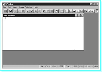
Figure 3.3: Windbg opening screen
Now press the step into button 
Click OK in the information window and then press the step into button again. Your source code now appears in a Windbg child window behind the Command window. Minimize the Command window. Next select View and then Registers to open a window that shows contents of the 80×86 registers. Then select View and Memory… to open a window that shows contents of memory. For this window you must enter the starting memory address; for the example program, use &number1 as the starting address-the C/C++ address-of operator (&) is used to indicate the address of number1, the first item in the data section. Finally size and rearrange windows until your screen looks something like the screen shown in Fig. 3.4. Notice that the right edge of the example program's output window is visible under the Windbg window. The rest of the desktop is covered by the window in which the assembler and linker were run, as well as a small strip of Microsoft Word that the author was also using.
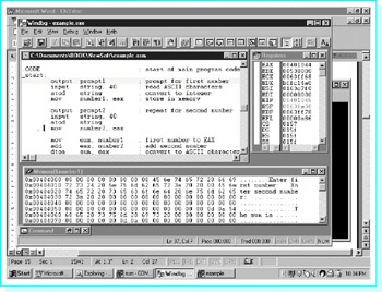
Figure 3.4: Windbg ready for tracing a program
The first statement of the example program is highlighted. Clicking the step into button causes this statement to be executed. Although this statement is a macro, it is executed as a single instruction, and Enter first number: appears on the output screen. (You can click on the edge of the output screen to put it on top.) Clicking step into again causes the input macro to be executed. When you enter a number and press return, Windbg returns to the debugger screen with the third statement highlighted. Two more clicks of the step into button causes the ASCII to double the macro to be executed, and the first mov instruction to be executed. The Windbg window now looks like the one shown in Fig. 3.5.

Figure 3.5: Windbg tracing a program
At this point, the Registers window shows that EAX contains 00000062, the 2's complement doubleword version of 98. The number 98 was entered in response to the prompt. You can see its ASCII codes stored in memory on the fourth line of the Memory window. Each line of the Memory window has three parts: its starting address, hex values for the bytes stored at that address, and printable characters that correspond to those bytes, if any. The first five characters of the fourth line are the end of prompt2, ASCII codes for r and colon, two spaces, and a null byte. The 40 bytes reserved for string come next in memory, and the first four have been replaced by 39, 38, 00, and 0A, ASCII codes for 98, a null byte, and a line feed. When 98 and Enter were pressed, the operating system stored 39 and 38 plus a carriage return character and a line feed character. The input macro replaced the carriage return by a null byte, but you can still see the line feed in memory. The atod macro scanned these ASCII codes to produce the value in EAX. The Memory window also shows a value of 62 00 00 00 for number1, the bytes of the number stored backwards, copied there by the mov instruction.
The rest of the program is traced similarly. Figure 3.6 shows Windbg just before program termination. The Memory window has been scrolled to show the part containing the output label. At this point, 35 has been entered for the second number, the sum 98 + (−35) has been calculated as a 2's complement number still visible in EAX, and this sum has been converted to an 11-byte-long string by the dtoa macro. You can see ten ASCII space characters (20) in memory prior to the codes for 6 and 3, 36 and 33.
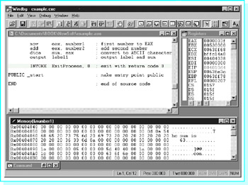
Figure 3.6: Windbg before program termination
Exercises 3.3
- Suppose that EXAMPLE.ASM is assembled and linked according to the first instructions (non-debugging) in this section. What additional files are generated by the assembler? By the linker?
- Suppose that EXAMPLE.ASM is assembled and linked according to the second instructions (debugging) in this section. What additional files are generated by the assembler? By the linker?
Programming Exercises 3.3
- Run the example program given in this section. Use a text editor to create the source code file EXAMPLE.ASM or copy it from the book's CD. Assemble, link, and execute it without generating debugging code. Run the program several times with different data.
- Trace the example program given in this section. Use a text editor to create the source code file EXAMPLE.ASM or copy it from the book's CD. Assemble, link, and execute it, generating debugging code. Trace the program several times with different data.
- Modify the example program given in this section to prompt for, input, and add three numbers. Call the source code file ADD3.ASM. Follow steps parallel to those of this section to assemble and link the program, producing ADD3.EXE. Run ADD3 several times with different data. Use the debugger if you have any trouble or if you want to trace the execution.
- The instruction
sub eax, label
will subtract the word at label from the word already in the EAX register. Modify the example program given in this section to prompt for and input two numbers, and then subtract the second number from the first. Call the source code file SUBTRACT.ASM. Follow steps parallel to those of this section to assemble and link the program, producing SUBTRACT.EXE. Run SUBTRACT several times with different data.
The Assembler Listing File
The ML assembler can produce a listing file as part of the assembly process. This .LST file shows the source code, the object code to which it is translated, and additional information. Examination of the listing file can help you understand the assembly process. When your source file contains errors, this .LST file displays error messages at the points of the errors, helping to locate the offending statements.
Suppose that we modify the example program EXAMPLE.ASM from Fig. 3.1, changing
 atod string ; convert to integer
 mov number1, eax ; store in memory
to
 atod eax, string ; convert to integer
 mov number1, ax ; store in memory
This introduces two errors: The atod macro only allows one operand, and the source and destination operands for the mov instruction are different sizes. Suppose that this revised file is stored in EXAMPLE1.ASM.
An additional switch, /Fl (uppercase F, lowercase letter l), is needed to generate a listing file during assembly
ml /c /coff /Fl example1.asm
When this command is entered at a DOS prompt, the console shows
 Assembling: example1.asm
example1.asm(32): error A2022: instruction operands must be the
same size
example1.asm(31): error A2052: forced error : extra operand(s) in
ATOD
 atod(7): Macro Called From
 example1.asm(31): Main Line Code
These error messages are fairly helpful-they indicate errors on lines 32 and 31 of the source file and describe the errors. However, if you look at the corresponding part of EXAMPLE1.LST, you see
00000000 _start:
 output prompt1 ; prompt for first number
 input string, 40 ; read ASCII characters
 atod eax, string ; convert to integer
 1 .ERR
example1.asm(31): error A2052: forced error : extra operand(s) in ATOD
 atod(7): Macro Called From
 example1.asm(31): Main Line Code
 mov number1, ax ; store in memory
example1.asm(32): error A2022: instruction operands must be the same size

 output prompt2 ; repeat for second number
with the error messages under the statements with the errors. Viewing the listing file frequently makes it easier to find errors in source code.
Figure 3.7 shows a listing file for EXAMPLE.ASM, the original example program without errors. Parts of this file will be examined to better understand the assembly process.
Microsoft (R) Macro Assembler Version 6.11 08/04/97 21:21:16
example.asm Page 1 - 1
 ; Example assembly language program - adds two numbers
 ; Author: R. Detmer
 ; Date: revised 7/97

 .386
 .MODEL FLAT

 ExitProcess PROTO NEAR32 stdcall, dwExitCode:DWORD

 INCLUDE io.h ; header file for input/output
 C ; IO.H - header file for I/O macros
 C ; 32-bit version for flat memory model
 C ; R. Detmer July 1997
 C .NOLIST ; turn off listing
 C .LIST ; begin listing
 C
= 0000000D cr EQU 0dh ; carriage return character
 Lf EQU 0ah ; line feed
 -STACK 4096 ; reserve 4096-byte stack

00000000 .DATA ; reserve storage for data
00000000 00000000 number1 DWORD ?
00000004 00000000 number2 DWORD ?
00000008 00000000 number1 DWORD ?
00000008 45 6E 74 65 72 prompt1 BYTE "Enter first number: ", 0
 20 66 69 72 73
 74 20 6E 75 6D
 62 65 72 3A 20
 20 00
0000001E 45 6E 74 65 72 prompt2 BYTE "Enter second number: ", 0
 20 73 65 63 6F
 6E 64 20 6E 75
 6D 62 65 72 3A
 20 20 00
 00000035 00000028 [ string BYTE 40 DUP (?)
 00
 ]
 0000005D 0D 0A 54 68 65 label1 BYTE cr, Lf, "The sum is "
 20 73 75 6D 20
 69 73 20
 0000006A 0000000B [ sum BYTE 11 DUP (?)
 00
 ]
 00000075 0D 0A 00 BYTE cr, Lf, 0

 00000000 .CODE ; start of main program code
 00000000 _start:
 output prompt1 ; prompt for first number
 input string, 40 ; read ASCII characters
 atod strin ; convert to integer
 0000002E A3 00000000 R mov number1, eax ; store in memory

 output prompt2 ; prompt for second number
 input string, 40
 atod strin
 00000061 A3 00000004 R mov number2, eax

 00000066 A1 00000000 R mov eax, number1 ; first number to EAX
 0000006B 03 05 000000 R ADD eax, number1 ; add second number
 dtoa sum, eax ; convert to ASCII characters
 output label1 ; output label and sum

 INVOKE ExitProcess, 0, ; exit with return code 0

 PUBLIC_start ; make entry point public
 END ; end of source code

Microsoft (R) Macro Assembler Version 6.11 08/04/97 21:21:16
example.asm Symbols 2 - 1


Macros:

 N a m e Type
atod . . . . . . . . . . . . . . Proc
atoi . . . . . . . . . . . . . . Proc
dtoa . . . . . . . . . . . . . . Proc
input . . . . . . . . . . . . . . Proc
itoa . . . . . . . . . . . . . . Proc
output . . . . . . . . . . . . . Proc

Segments and Groups:

 N a m e Size Length Align Combine Class
FLAT . . . . . . . . . . . . . . GROUP
STACK . . . . . . . . . . . . . 32 Bit 00001000 Dword Stack 'STACK'
_DATA . . . . . . . . . . . . . 32 Bit 00001078 Dword Public 'DATA'
_TEXT . . . . . . . . . . . . . 32 Bit 00000097 Dword Public 'STACK'

Procedures, parameters and locals:

 N a m e Type Value Attr

ExitProcess . . . . . . . . . . P Near 00000000 Flat Length= 00000000 External STDCALL

Symbols;

 N a m e Type Value Attr
@CodeSize . . . . . . . . . . . Number 00000000h
@DataSize . . . . . . . . . . . Number 00000000h
@Interface . . . . . . . . . . . Number 00000000h
@Model . . . . . . . . . . . Number 00000007h
@code . . . . . . . . . . . Text _TEXT
@data . . . . . . . . . . . Text FLAT
@fardata? . . . . . . . . . . . Text FLAT
@fardata . . . . . . . . . . . Text FLAT
@stack . . . . . . . . . . . Text FLAT
Lf . . . . . . . . . . . . . . . Number 0000000Ah
_start . . . . . . . . . . . . . L Near 00000000 _TEXT Public
atodproc . . . . . . . . . . . . L Near 00000000 FLAT External
atoiproc . . . . . . . . . . . . L Near 00000000 FLAT External
cr . . . . . . . . . . . . . . . Number 0000000Dh
dtoaproc . . . . . . . . . . . . L Near 00000000 FLAT External
inproc . . . . . . . . . . . . . L Near 00000000 FLAT External
itoaproc . . . . . . . . . . . . L Near 00000000 FLAT External
labell . . . . . . . . . . . . . Byte 0000005D _DATA
number1 . . . . . . . . . . . . Dword 00000000 _DATA
number2 . . . . . . . . . . . . Dword 00000004 _DATA
outproc . . . . . . . . . . . . L Near 00000000 FLAT External
prompt1 . . . . . . . . . . . . Byte 00000008 _DATA
prompt2 . . . . . . . . . . . . Byte 0000000E _DATA
string . . . . . . . . . . . . . Byte 00000035 _DATA
sum . . . . . . . . . . . . . . Byte 0000006A _DATA
 0 Warnings
 0 Errors
Figure 3.7: EXAMPLE.LST listing file
The listing begins by echoing comments and directives at the beginning of the source code file. Following the INCLUDE directive, several lines from IO.H are shown. These lines are marked with the letter C to show they come from an included file. In particular, you see the .NOLIST directive that suppressed listing of most of IO.H, and the .LIST directive that resumed listing of the rest of the source file. For each EQU directive the assembler shows the value to which the symbol is equated as eight hex digits. This listing shows 0000000D for cr and 0000000A for Lf.
The leftmost column for the rest of the listing shows the offset (distance) of each directive or instruction from the beginning of the segment that contains it. This offset is in bytes. The line
00000000 00000000 number1 DWORD ?
shows an offset of 00000000 since this statement is the first in the data segment. The assembler then shows the object code, a doubleword with value 00000000. Since this DWORD directive reserves four bytes, the assembler uses 00000004 for the offset of the next statement.
00000004 00000000 number2 DWORD ?
Again four bytes are reserved with contents 00000000.
Now eight bytes have been reserved, so the offset of the next item is 00000008. The next two entries show the initial values assigned by the BYTE directives at prompt1 and prompt2.
 00000008 45 6E 74 65 72 prompt1 BYTE "Enter first"
 20 66 69 72 73
 74 20 6E 75 6D
 62 65 72 3A 20
 20 00
 0000001E 45 6E 74 65 72 prompt2 BYTE "Enter second"
 20 73 65 63 6F
 6E 64 20 6E 75
 6D 62 65 72 3A
 20 20 00
The offset for prompt2 can be calculated by taking the offset 00000008 of prompt1 plus the number of bytes reserved for prompt1, 22 (1616); and finding the sum 0000001E. Similarly, the offset of the statement following prompt2 will be at 0000001E + 17 = 00000035 since there are 23 (1716) bytes generated in the second prompt.
The notation
 00000035 00000028 [ string BYTE 40 DUP (?)
 00
 ]
shows that this BYTE directive generates 2816 (4010) bytes of storage, each initialized to 00. The remaining statements in the data segment illustrate no new concepts.
The assembly listing for the code segment shows, in hex, the offset and the object code of each instruction. Some assemblers may also show the offset for a macro, that is, the address of the first instruction to which it expands. The first byte of the machine code for each instruction is called its opcode (operation code). By looking at an opcode as the program executes, the 80×86 knows what kind of operation is to be done and whether or not there are more bytes of the instruction. The object code for a single instruction can be from one to 16 bytes long.
The line
0000002E A3 00000000 R mov number1, eax
shows that this instruction starts at an offset of 0000002E and has five bytes of object code, beginning with the opcode A3. The opcode A3 tells the 80×86 to copy the contents of the EAX register to the address given in the next four bytes of the instruction. The notation R indicates that the address is relocatable, that is, the linker and loader will determine the run-time address, substituting it for 00000000 in this instruction in the code that is actually executed at run time. Figure 3.5 showed that address as 00404000 for one run of the program-it may be different every time the program is executed.
The add instruction
0000006B 03 05 00000004 R add eax, number2
starts at an offset of 0000006B and has an opcode of 03, one of several opcodes used for different add instructions. The 03 opcode itself is used for add instructions with several different formats, and the CPU must also look at the next byte to determine what the operands are. The 05 byte tells the 80×86 that the EAX register is the destination for the sum (and one source) and that the other source is in memory at the address given in the next four bytes. Chapter 9 provides more details about formats of 80×86 instructions and how they are assembled.
The final part of the assembly listing shows all the symbols that are used in the program. The first few lines show the macro names that are defined by including IO.H even though not all are used in this program. After listing segment and procedure names, the assembler shows the remaining symbols. This list includes familiar symbols such as Lf, number2, and _start. It also shows several symbols starting with an at sign (@); these give information about the assembly process. Some of the remaining symbols are names of procedures that are called by the macros in IO.H; for instance, atoiproc is called by the atod macro.
Exercises 3.4
Answer the following questions by looking at the assembly listing in Fig. 3.7.
- What are the ASCII codes for characters in the string "The sum is"?
- What is the offset of the label sum in the data section?
- If the following statements were added at the end of the data section (just before .CODE), what offsets and values would appear for them in the assembly listing?
extra DWORD 999
label2 BYTE "The End", cr, Lf, 0
(Hint: An ASCII/hexadecimal conversion chart is useful for this problem.)
- How many bytes of object code are generated by the first three statements in the example program (the output, input, and atod macros)?
Constant Operands
This section discusses formats of constant operands used in BYTE, DWORD, and WORD directives. The information also applies to instructions since constants are written the same way in directives and in instructions.
Numeric operands can be expressed in decimal, hexadecimal, binary, or octal notations. The assembler assumes that a number is decimal unless the number has a suffix indicating another base or a .RADIX directive (not used in this book) changes the default number base. The suffixes that may be used are
|
Suffix |
Base |
Number System |
|---|---|---|
|
H |
16 |
hexadecimal |
|
B |
2 |
binary |
|
O or Q |
8 |
octal |
|
none |
10 |
decimal |
Any of these suffixes can be coded in uppercase or lowercase. Octal is not used often, but when it is used, Q is easier to read than O, although either letter will designate that the number is octal.
The directive
mask BYTE 01111101b
reserves one byte of memory and initializes it to 7D. This is equivalent to any of the following directives
 mask BYTE 7dh
 mask BYTE 125
 mask BYTE 175q
since 11111012 = 7D16 = 12510 = 1758. The choice of number systems often depends on the use planned for the constant. A binary value is appropriate when you need to think of the value as a sequence of eight separate bits, for instance in a logical operation (covered in Chapter 8).
A BYTE directive reserves storage for one or more bytes of data. If a data value is numeric, it can be thought of as signed or unsigned. The decimal range of unsigned values that can be stored in a single byte is 0 to 255. The decimal range of signed values that can be stored in a single byte is 128 to 127. Although the assembler will allow larger or smaller values, normally you restrict numeric operands for BYTE directives to 128 to 255. The comments in the following examples indicate the initial values of the bytes that are reserved.
 byte1 BYTE 255 ; value is FF
 byte2 BYTE 127 ; value is 7F
 byte3 BYTE 91 ; value is 5B
 byte4 BYTE 0 ; value is 00
 byte5 BYTE -1 ; value is FF
 byte6 BYTE -91 ; value is A5
 byte7 BYTE -128 ; value is 80
The situation for DWORD and WORD directives is similar. A DWORD directive reserves a doubleword of storage; since eight bytes can store a signed number in the range −2,147,483,648 to 2,147,483,647 or an unsigned number from 0 to 4,294,967,295, it makes sense to restrict operand values to the range −2,147,483,648 to 4,294,967,295. Similarly, operands for a WORD directive should be restricted to the range 32,768 to 65,535. The examples below give the initial values reserved for a few doublewords and words.
 double1 DWORD 4294967295 ; value is FFFFFFFF
 double2 DWORD 4294966296 ; value is FFFFFC18
 double3 DWORD 0 ; value is 00000000
 double4 DWORD -1 ; value is FFFFFFFF
 double5 DWORD -1000 ; value is FFFFFC18
 double6 DWORD -2147483648 ; value is 80000000
 word1 WORD 65535 ; value is FFFF
 word2 WORD 32767 ; value is 7FFF
 word3 WORD 1000 ; value is 03E8
 word4 WORD 0 ; value is 0000
 word5 WORD -1 ; value is FFFF
 word6 WORD -1000 ; value is FC18
 word7 WORD -32768 ; value is 8000
One of the points of the previous examples is that different operands can result in the same stored value. For instance, note that the WORD directives with operands 65535 and 1 both generate words containing FFFF. This value can be thought of as either the unsigned number 65,535 or the signed number 1, depending on the context in which it is used.
As previously stated, the bytes of a word or doubleword are actually stored backwards so that, for example, the initial value of word6 previous is actually 18FC. This book will concentrate on the logical values rather than the way that they are stored.
The BYTE directive allows character operands with a single character or string operands with many characters. Either apostrophes (') or quotation marks (") can be used to designate characters or delimit strings. They must be in pairs; you can not put an apostrophe on the left and a quotation mark on the right. A string delimited with apostrophes can contain quotation marks, and one delimited with quotation marks can contain apostrophes, making it possible to have strings containing these special characters. Unless there is reason to do otherwise, this book will follow the convention of putting single characters between apostrophes and strings of characters between quotation marks.
Each of the following BYTE directives is allowable.
 char1 BYTE 'm' ; value is 6D
 char2 BYTE 6dh ; value is 6D
 string1 BYTE "Joe" ; value is 4A 6F 65
 string2 BYTE "Joe's" ; value is 4A 6F 65 27 73
If you are trying to store the letter m rather than the number 6D16, then there is no reason to look up the ASCII code and enter it as in char2-the assembler has a built-in ASCII chart! Notice that the delimiters, the apostrophes or quotation marks on the ends of the character or string, are not themselves stored.
The assembler allows restricted usage of character operands in DWORD or WORD directives. However, there is little reason to do this.
You have already seen examples of BYTE directives with multiple operands separated by commas. DWORD and WORD directives also allows multiple operands. The directive
words WORD 10, 20, 30, 40
reserves four words of storage with initial values 000A, 0014, 001E, and 0028. The DUP operator can be used to generate multiple bytes or words with known values as well as uninitialized values. Its use is limited to BYTE, DWORD, WORD, and other directives that reserve storage. The directive
DblArray DWORD 100 DUP(999)
reserves 100 doublewords of storage, each initialized to 000003E7. This is an effective way to initialize elements of an array. If one needs a string of 50 asterisks, then
stars BYTE 50 DUP('*')
will do the job. If one wants 25 asterisks, separated by spaces,
starsAndSpaces BYTE 24 DUP("* "), '*'
reserves these 49 bytes and assigns the desired initial values.
An operand of a BYTE, DWORD, WORD, or other statement can be an expression involving arithmetic or other operators. These expressions are evaluated by the assembler at assembly time, not at run time, with the resulting value used for assembly. It is usually not helpful to use an expression instead of the constant of equivalent value, but sometimes it can contribute to clearer code. The following directives are equivalent, each reserving a word with an initial hex value of 0090.
 gross WORD 144
 gross WORD 12*12
 gross WORD 10*15 - 7 + 1
Each symbol defined by a BYTE, DWORD,or WORD directive is associated with a length. The assembler notes this length and checks to be sure that symbols are used appropriately in instructions. For example, the assembler will generate an error message if
char BYTE 'x'
is used in the data segment and
mov ax, char
appears in the code segment-the AX register is a word long, but char is associated with a single byte of storage.
The Microsoft assembler recognizes several additional directives for reserving storage. These include QWORD for reserving a quadword, TBYTE for a 10-byte integer, REAL4, for reserving a 4-byte floating point number, REAL8 for 8-byte floating point, and REAL10 for 10-byte floating point. It also has directives to distinguish signed bytes, words, and doublewords from unsigned. We will rarely use these directives.
Exercises 3.5
Find the initial values that the assembler will generate for each directive below.
|
1. |
byte1 |
BYTE |
10110111b |
|
2. |
byte2 |
BYTE |
33q |
|
3. |
byte3 |
BYTE |
0B7h |
|
4. |
byte4 |
BYTE |
253 |
|
5. |
byte5 |
BYTE |
108 |
|
6. |
byte6 |
BYTE |
-73 |
|
7. |
byte7 |
BYTE |
‘D' |
|
8. |
byte8 |
BYTE |
‘d' |
|
9. |
byte9 |
BYTE |
"John's program" |
|
10. |
byte10 |
BYTE |
5 DUP("<>") |
|
11. |
byte11 |
BYTE |
61 + 1 |
|
12. |
byte12 |
BYTE |
‘c' - 1 |
|
13. |
dword1 |
DWORD |
1000000 |
|
14. |
dword2 |
DWORD |
1000000b |
|
15. |
dword3 |
DWORD |
1000000h |
|
16. |
dword4 |
DWORD |
1000000q |
|
17. |
dword5 |
DWORD |
-1000000 |
|
18. |
dword6 |
DWORD |
-2 |
|
19. |
dword7 |
DWORD |
-10 |
|
20. |
dword8 |
DWORD |
23B8C9A5h |
|
21. |
dword9 |
DWORD |
0, 1, 2, 3 |
|
22. |
dword10 |
DWORD |
5 DUP(0) |
|
23. |
word1 |
WORD |
1010001001011001b |
|
24. |
word2 |
WORD |
2274q |
|
25. |
word3 |
WORD |
2274h |
|
26. |
word4 |
WORD |
0ffffh |
|
27. |
word5 |
WORD |
5000 |
|
28. |
word6 |
WORD |
-5000 |
|
29. |
word7 |
WORD |
-5, -4, -3, -2, -1 |
|
30. |
word8 |
WORD |
8 DUP(1) |
|
31. |
word9 |
WORD |
6 DUP(-999) |
|
32. |
word10 |
WORD |
100/2 |
Instruction Operands
There are three basic types of instruction operands; some are constants, some designate CPU registers, and some reference memory locations. There are several ways of referencing memory; two simpler ways will be discussed in this section, and more complex methods will be introduced as needed later in the book.
Many instructions have two operands. In general, the first operand gives the destination of the operation, although it may also designate one of the sources. The second operand gives the source (or a source) for the operation, never the destination. For example, when
mov al, '/'
is executed, the byte 2F (the ASCII code for the slash /) will be loaded into the AL register, replacing the previous byte. The second operand ‘/' specifies the constant source. When
add eax, number1
is executed, EAX gets the sum of the doubleword designated by number1 and the old contents of EAX. The first operand EAX specifies the source for one doubleword as well as the destination for the sum; the second operand number1 specifies the source for the other of the two doublewords that are added together.
Figure 3.8 lists the addressing modes used by the Intel 80×86 microprocessor, giving the location of the data for each mode. Memory addresses can be calculated several ways; Fig. 3.9 lists the two most common.
|
Mode |
Location of data |
|---|---|
|
immediate |
in the instruction itself |
|
register |
in a register |
|
memory |
at some address in memory |
Figure 3.8: 80×86 addressing modes
|
Memory mode |
Location of data |
|---|---|
|
direct |
at a memory location whose address (offset) is built into the instruction |
|
register indirect |
at a memory location whose address is in a register |
Figure 3.9: Two 80×86 memory addressing modes
For an immediate mode operand, the data to be used is built into the instruction before it is executed; once there it is constant.[2] Normally the data is placed there by the assembler, although it can be inserted by the linker or loader, depending on the stage at which the value can be determined. The programmer writes an instruction including an actual value, or a symbol standing for a constant value. For a register mode operand, the data to be used is in a register. To indicate a register mode operand, the programmer simply codes the name of the register. A register mode operand can also specify a register as a destination, but an immediate mode operand cannot be a destination.
In each of the following examples, the first operand is register mode and the second operand is immediate mode. The object code (taken from the assembler listing file) is shown as a comment. For the instruction
mov al, '/' ; B0 2F
the ASCII code 2F for the slash is the second byte of the instruction, and is placed there by the assembler. For the instruction
add eax, 135 ; 05 00000087
the doubleword length 2's complement version of 135 is assembled into the last four bytes of the instruction.
Any memory mode operand specifies using data in memory or specifies a destination in memory. A direct mode operand has the 32-bit address built into the instruction. Usually the programmer will code a symbol that is associated with a BYTE, DWORD,or WORD directive in the data segment or with an instruction in the code segment. The location corresponding to such a symbol will be relocatable so that the assembler listing shows an assembly-time address that may be adjusted later. In the statement
add eax, number2 ; 05 00000004
from the example program in Fig. 3.1, the first operand is register mode and the second operand is direct mode. The memory operand has been encoded as the 32-bit address 00000004, the offset of number2 in the data segment. The first operand of the instruction
add eax, [edx] ; 03 02
is register mode, and the second operand is register indirect mode. We will later discuss how the assembler gets the object code 03 02 for this instruction, but for now notice that it is not long enough to contain a 32-bit memory address. Instead, it contains bits that say to use the address in the EDX register to locate a doubleword in memory to add to the doubleword already in EAX. In other words, the second number is not in EDX, but its address is. The square bracket notation ([]) indicates indirect addressing with MASM 6.11. Figure 3.10 illustrates how register indirect addressing works in this example.
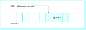
Figure 3.10: Register indirect addressing
Any of the general registers EAX, EBX, ECX, and EDX or the index registers ESI and EDI can be used for register indirect addressing. The base pointer EBP can also be used, but for an address in the stack rather than for an address in the data segment. Although the stack pointer ESP can be used for register indirect addressing in certain special circumstances, we will have no need to do so.
With register indirect mode, the register serves like a pointer variable in a high-level language. The register contains the location of the data to be used in the instruction, not the data itself. When the size of the memory operand is ambiguous, the PTR operator must be used to give the size to the assembler. For example, the assembler will give an error message for
mov [ebx], 0
since it cannot tell whether the destination is a byte, word, or doubleword. If it is a byte, you can use
mov BYTE PTR [ebx], 0
For a word or doubleword destination, use WORD PTR or DWORD PTR, respectively. In an instruction like
add eax, [edx]
it is not necessary to use DWORD PTR [edx] since the assembler assumes that the source will be a doubleword, the size of the destination EAX.
A few instructions have no operands. Many have a single operand. Sometimes an instruction with no operands requires no data to operate on or an instruction with one operand needs only one value. Other times the location of one or more operands is implied by the instruction and is not coded. For example, one 80×86 instruction for multiplication is mul; it might be coded
mul bh
Only one operand is given for this instruction; the other value to be multiplied is always in the AL register. (This instruction will be explained more fully in the next chapter.)
Exercises 3.6
Identify the mode of each operand in the following instructions. Assume that the instructions are in a program also containing the code
 cr EQU 0dh
 .DATA
 value DWORD ?
 char BYTE ?
- mov value, 100
- mov ecx, value
- mov ah, cr
- mov eax, [esi]
- mov [ebx], ecx
- mov char, '*'
- add value, 1
- add WORD PTR [ecx], 10
[2]One can write self-modifying code; that is, code that changes its own instructions as it executes. This is considered a very poor programming practice.
Input Output Using Macros Defined in IO H
In order to write useful programs, you need to be able to input and output data. Operating systems provide routines to aid in these tasks. A typical input routine might wait for a character to be pressed on the keyboard, and then return the ASCII code for that character in a register. An output routine might display at the terminal the characters in a string up to some terminating character like a dollar sign.
High-level languages usually provide for input or output of numeric data in addition to character or string data. A numeric input routine in a high-level language accepts a string of character codes representing a number, converts the characters to a 2's complement or floating point form, and stores the value in a memory location associated with some variable name. Conversely, output routines of high-level languages start with a 2's complement or floating point number in some memory location, convert it to a string of characters that represent the number, and then output the string. Operating systems usually do not provide these services, so the assembly language programmer must code them.
The file IO.H provides a set of macro definitions that make it possible to do input, output, and numeric conversion fairly easily. Each macro looks much like an 80×86 instruction, but actually expands to several instructions, including a call to an external procedure to do most of the work. The source code for these external procedures is in the file IO.ASM; the assembled version of this file is IO.OBJ. We will examine the code in IO.ASM in later chapters of this book.
Figure 3.11 lists the macros defined in IO.H and briefly describes them. Additional explanation then follows. The macros will be used in programs in subsequent chapters.
|
Name |
Parameter(s) |
Action |
Flags affected |
|---|---|---|---|
|
dtoa |
destination, source |
Converts the doubleword at source (register or memory) to an eleven-byte-long ASCII string at destination. |
None |
|
atod |
source |
Scans the string starting at source for + or - followed by digits, interpreting these characters as an integer. The corresponding 2's complement number is put in EAX. The offset of the terminating nondigit character is put in ESI. For input error, 0 is put in EAX. Input error occurs if the number has no digits or is out of the range 2,147,483,647 to 2,147,483,647. |
OF = 1 for input error; OF = 0 otherwise. Other flag values correspond to the result in EAX. |
|
itoa |
destination, source |
Converts the word at source (register or memory) to a six-byte-long ASCII string at destination. |
None |
|
atoi |
source |
Similar to atod, except that the resulting number is placed in AX. The range accepted is −32,768 to 32,767. |
similar to atod |
|
output |
source |
Displays the string starting at source. The string must be null-terminated. |
None |
|
input |
destination, length |
Inputs a string up to length characters long and stores it at destination. |
None |
Figure 3.11: Macros in IO.H
The output macro is used to output a string of characters to the monitor. Its source operand references a location in the data segment, usually the name on a BYTE directive. Characters starting at this address are displayed until a null character is reached; the null character terminates the output. It is important that source string contains ASCII codes for characters that can be displayed. Most of these will be printable characters, although it makes sense to include carriage return, line feed, and a few other special characters. If you attempt to use the output macro to display non-ASCII data (such as a doubleword integer in 2's complement form), there will be strange results.
The output macro does not change any register contents, including the flag register.
The input macro is used to input a string of characters from the keyboard. It has two parameters, destination and length. The destination operand references a string of bytes in the data segment and the length operand references the number of bytes reserved in that string. The destination string should be at least two bytes longer than the actual number of characters to be entered; this allows for the operating system to add carriage return and linefeed characters when you press Enter. The input macro replaces the carriage return character by a null byte, so that the result is a null-terminated string stored at destination.
The input macro changes only memory at the specified destination. It does not change any register contents, including the flag register.
The name dtoa (double to ASCII) describes the function of this macro. It takes a doubleword length source containing a 2's complement integer, and produces a string of exactly 11 ASCII characters representing the same integer in the decimal number system. The source operand is normally a register or memory operand. The destination will always be a 11-byte area of storage in the data segment reserved with a BYTE directive. The string of characters produced will have leading blanks if the number is shorter than 11 characters. If the number is negative, a minus sign will immediately precede the digits. Since the decimal range for a word-length 2's complement number is -2147483648 to 2147483647, there is no danger of generating too many characters to fit in a 11-byte-long field. A positive number will always have at least one leading blank.
The dtoa macro alters only the 11-byte area of memory that is the destination for the ASCII codes. No registers are changed, including the flag register.
The atod (ASCII to double) macro is in many ways the inverse of the dtoa macro. It has only a single operand, the address of a string of ASCII character codes in storage, and it scans this area of memory for characters that represent a decimal number. If it finds characters for a decimal number in the range 2,147,483,648 to 2,147,483,647, then the doubleword-length 2's complement form of the number is placed in the EAX register.
The source string may contain any number of leading blanks. These are skipped by atod. There may then be the ASCII code for −(minus) or the ASCII code for + (plus). A number is assumed positive if there is no leading sign. Codes for digits 0 through 9 must immediately follow the optional sign. Once a digit code is encountered, atod continues scanning until any character other than a digit is encountered. Such a character terminates the scan.
Problems may arise when the atod macro is used. The macro may find no digit code; this would be the case if a space character were between a minus sign and the first digit of a number, or if the source string began with the code for a letter. The decimal number could be too large to store in doubleword-length 2's complement form. If any of these things occurs, a value of 00000000 is placed in EAX and the overflow flag OF is set to 1.
If atod is able to successfully convert a string of ASCII characters, then the overflow flag OF is set to 0. In all cases, the SF, ZF, and PF flags are set according to the value returned in EAX as follows:
- SF is 1 if the number is negative, and 0 otherwise
- ZF is 1 if the number is 0, and 0 if the number is nonzero
- PF reflects the parity of the number returned in EAX
In addition, CF is 0 and DF is unchanged. No registers other than EAX and the flag register are changed.
The atod macro will typically be used immediately after the input macro. The input macro produces a string of ASCII codes, including a trailing null character. When atod is applied to this string, the null character serves as a terminating character for the scan. If atod is applied to a string that comes from some source other than input, the programmer must ensure that it has some trailing nondigit character to prevent atod from scanning too far.
The atoi (ASCII to integer) and itoa (integer to ASCII) macros are the word-length versions of atod and dtoa. The atoi macro scans a string of characters and produces the corresponding word-length 2's complement value in AX. The itoa macro takes the 2's complement value stored in a word-length source and produces a string of exactly six characters representing this value in decimal. These macros are useful if you are dealing with values in the range −32,768 to 32,767.
Exercises 3.7
- Why wasn't the dtoa macro designed to produce a smaller number of ASCII codes? What is important about the number 11?
- Why wasn't the itoa macro designed to produce a smaller number of ASCII codes? What is important about the number six?
- Given the data segment definition
response1 BYTE 10 DUP(?)
and the code segment macro
input response1
- What ASCII codes will be stored in the data segment if
-578
is typed at run time?
- If the macro
atod response1
follows the above input macro, what will be in the EAX register and what will be the values of the OF, SF, and ZF flags?
- What ASCII codes will be stored in the data segment if
- Given the data segment definition
response2 BYTE 10 DUP(?)
and the code segment macro
input response2
- what ASCII codes will be stored in the data segment if
123456
is typed at run time?
- If the macro
atoi response2
follows the above input macro, what will be in the AX register and what will be the values of the OF, SF, and ZF flags?
- what ASCII codes will be stored in the data segment if
- Suppose a program contains the data segment definitions
value1 DWORD ?
result1 BYTE 11 DUP(?)
 BYTE ' sum', 0dh, 0ah, 0
and the code segment macro
dtoa result1, value1
- Assuming that at run time the word referenced by value1 contains FFFFFF1A, what codes will be placed in storage at result1 by the dtoa macro?
- If the dtoa macro is followed by
output result1
what will be displayed on the monitor?
- Suppose a program contains the data segment definitions
result2 BYTE 6 DUP(?)
 BYTE ' total', 0dh, 0ah, 0
and the code segment macro
itoa result2, BX
- Assuming that at run time the BX register contains 1AFF, what codes will be placed in storage at result2 by the itoa macro?
- If the itoa macro is followed by
output result5
what will be displayed on the monitor?
Summary
Chapter 3 introduced 80×86 assembly language as translated by the Microsoft MASM assembler.
An assembly language comment always starts with a semicolon. Other statements have the format
name mnemonic operand(s) ;comment
where some of these fields may be optional.
The three types of assembly language statements are:
- instructions-each corresponds to a CPU instruction
- directives-tell the assembler what to do
- macros-expand into additional statements
An assembly language program consists mainly of a data segment in which variables are defined and a code segment that contains statements to be executed at run time. To get an executable program, one must translate the program to object code using an assembler and then link the program using a linker. An executable program can be traced with a debugger like Windbg.
BYTE, DWORD, or WORD directives reserve bytes, doublewords, or words of storage and optionally assign initial values.
Instruction operands have three modes:
- immediate-data built into the instruction
- register-data in a register
- memory-data in storage
Memory mode operands come in several formats, two of which are
- direct-at an address in the instruction
- register indirect-data at an address in a register
Several macros for input and output are defined in the file IO.H. They call procedures whose assembled versions are in the file IO.OBJ. The macros are:
- output-to display a string on the monitor
- input-to input a string from the keyboard
- atod-to convert a string to a doubleword-length 2's complement number
- dtoa-to convert a doubleword-length 2's complement number to a string
- atoi-to convert a string to a word-length 2's complement number
- itoa-to convert a word-length 2's complement number to a string
Preface
- Representing Data in a Computer
- Parts of a Computer System
- Elements of Assembly Language
- Basic Instructions
- Branching and Looping
- Procedures
- String Operations
- Bit Manipulation
- The Assembly Process
- Floating-Point Arithmetic
- Decimal Arithmetic
- Input/Output
- Appendix A Hexadecimal/ASCII conversion
- Appendix B Useful MS-DOS Commands
- Appendix C MASM 6.11 Reserved Words
- Appendix D 80x86 Instructions (by Mnemonic)
- Appendix E 80x86 Instructions (by Opcode)
EAN: 2147483647
Pages: 113
- ERP Systems Impact on Organizations
- ERP System Acquisition: A Process Model and Results From an Austrian Survey
- Context Management of ERP Processes in Virtual Communities
- Intrinsic and Contextual Data Quality: The Effect of Media and Personal Involvement
- Relevance and Micro-Relevance for the Professional as Determinants of IT-Diffusion and IT-Use in Healthcare
