Floating-Point Arithmetic
Overview
This book has concentrated on integer representations of numbers, primarily 2's complement since all 80x86 microprocessors have a variety of instructions to manipulate 2's complement numbers. Many 80x86 microprocessor systems-including all Pentium systems, systems with a 486DX, and other systems equipped with a floating-point coprocessor-also have the capability to manipulate numbers stored in floating-point format.
Section 1.5 described the IEEE format used to store floating-point values in 32 bits. The MASM assembler has directives that accept decimal operands and initialize storage using the IEEE format. There are two ways to do floating-point arithmetic with a PC. If you have a microprocessor with a floating-point unit built in or a floating-point coprocessor, then you can simply use the floating-point instructions. Otherwise, you can employ a collection of procedures that implement arithmetic operations such as addition and multiplication.
Section 10.1 describes the 80x86 floating-point architecture. Section 10.2 describes how to convert floating-point values to and from other formats, including ASCII. Section 10.3 shows floating-point emulation routines of addition, subtraction, multiplication, division, negation, and comparison operations-these routines are useful for floating-point operations on an 80x86 system without built-in floating-point instructions. The procedures in this section serve as examples of assembly language implementation of moderately complex, useful algorithms and also illustrate some techniques not covered earlier in this book. Section 10.4 gives a brief introduction into using in-line assembly code in C++ code, with C++ for input/output operations, and assembly language for floating-point operations. In-line assembly code is not restricted to floating-point instructions, however.
x86 Floating Point Architecture
As stated above, some 80x86 microprocessors do not have built-in floating point capability, depending instead on a floating-point coprocessor chip to execute floating-point instructions. Even with the ones that do, the floating-point unit (FPU) of the chip is almost independent of the rest of the chip. It has its own internal registers, completely separate from the familiar 80x86 registers. It executes instructions to do floating-point arithmetic operations, including commonplace operations such as addition or multiplication, and more complicated operations such as evaluation of some transcendental functions. Not only can it transfer floating-point operands to or from memory, it can also transfer integer or BCD operands to or from the coprocessor. Nonfloating formats are always converted to floating point when moved to a floating-point register; a number in internal floating-point format can be converted to integer or BCD format as it is moved to memory.
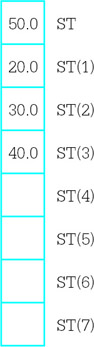
The FPU has eight data registers, each 80 bits long. A ten-byte floating-point format (also specified by IEEE standards) is used for values stored in these registers. The registers are basically organized as a stack; for example, when the fld (floating load) instruction is used to transfer a value from memory to the floating point unit, the value is loaded into the register at the top of the stack, and data stored in the stack top and other registers are pushed down one register. However, some instructions can access any of the eight registers, so that the organization is not a "pure" stack.
The names of the eight floating-point registers are
- ST, the stack top, also called ST(0),
- ST(1), the register just below the stack top,
- ST(2), the register just below ST(1),
- ST(3), ST(4), ST(5), ST(6), and
- ST(7), the register at the bottom of the stack.
In addition to the eight data registers, the floating-point unit has several 16-bit control registers. Some of the status word bits are assigned values by floating-point comparison instructions, and these bits must be examined in order for the 80x86 to execute conditional jump instructions based on floating-point comparison. Bits in the FPU control word must sometimes be set to ensure certain modes of rounding.
Before considering the floating-point instructions, a few notes are in order. Each floating-point mnemonic starts with the letter F, a letter that is not used as the first character of any nonfloating instruction. Most floating-point instructions act on the stack top ST and one other operand in another floating-point register or in memory. No floating-point instruction can transfer data between an 80x86 general register (such as EAX) and a floating-point register—transfers must be made using a memory location for intermediate storage. (There are, however, instructions to store the status word or the control word in AX.)
The floating-point instructions will be examined in groups, starting with instructions to push operands onto the stack. Figure 10.1 lists these mnemonics.
|
Mnemonic |
Operand |
Action |
|---|---|---|
|
fld |
memory (real) |
real value from memory pushed onto stack |
|
fild |
memory (integer) |
integer value from memory converted to floating point and pushed onto stack |
|
fbld |
memory (BCD) |
BCD value from memory converted to floating point and pushed onto stack |
|
fld |
st(num) |
contents of floating-point register pushed onto stack |
|
fld1 |
(none) |
1.0 pushed onto stack |
|
fldz |
(none) |
0.0 pushed onto stack |
|
fldpi |
(none) |
π(pi) pushed onto stack |
|
fldl2e |
(none) |
log2(e) pushed onto stack |
|
fldl2t |
(none) |
log2(10) pushed onto stack |
|
fldlg2 |
(none) |
log10(2) pushed onto stack |
|
fldln2 |
(none) |
loge(2) pushed onto stack |
Figure 10.1: Floating-point load instructions
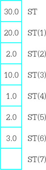
Some examples illustrate how these instructions work. Suppose that the floating-point register stack contains
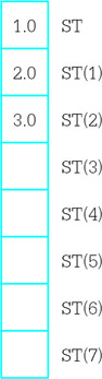
with values shown in decimal rather than in IEEE floating-point format. If the data segment contains
 fpValue REAL4 10.0
 intValue DWORD 20
 bcdValue TBYTE 30
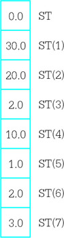
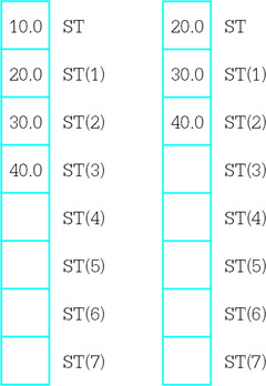
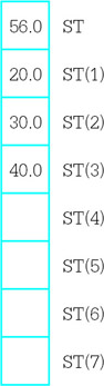
then the values assembled will be 41200000 for fpValue, 00000014 for intValue, and 00000000000000000030 for bcdValue. If the instruction fld fpValue is executed, the register stack will contain
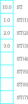
The original values have all been pushed down one register position on the stack. Starting with these values, if the instruction fld st(2) is executed, the register stack will contain
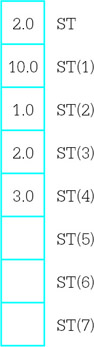
Notice that the value 2.0 from ST(2) has been pushed onto the top of the stack, but not removed from the stack. Starting with these values, assume that the instruction fild intValue is executed. The new contents of the register stack will be
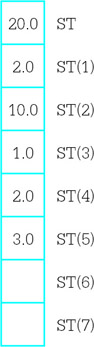
What is not obvious here is that the 32-bit value 00000014 is converted to an 80-bit floating-point value. An integer operand must be word length, doubleword length, or quadword length—byte length integer operands are allowed. This chapter does not show opcodes for floating-point instructions.
If the instruction fbld bcdValue is now executed, the stack values will become
where the 80 bit BCD value is converted to the very different 80 bit floating-point format. Finally, if the instruction fldz is executed, the register stack will contain
The stack is now full. No further value can be pushed onto the stack unless some value is popped from the stack, or the stack is cleared. The instruction finit initializes the floating-point unit and clears the contents of all eight registers. Often a program that uses the floating-point unit will include the statement
finit ; initialize the math processor
near the beginning of the code. It may be desirable to reinitialize the floating-point unit at points in the code, but normally this is not required since values will be popped from the stack, not allowed to accumulate on the stack.
You can trace floating-point operations using Windbg. Figure 10.2 shows a screen dump following execution of the code on the left pane. A floating-point window is shown in the right pane.
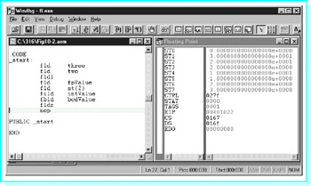
Figure 10.2: Windbg view of floating point execution
Figure 10.3 lists the floating-point instructions that are used to copy data from the stack top to memory or to another floating-point register. These instructions are mostly paired: One instruction of each pair simply copies ST to its destination while the other instruction is identical except that it copies ST to its destination and also pops ST off the register stack.
|
Mnemonic |
Operand |
Action |
|---|---|---|
|
fst |
st(num) |
replaces contents of ST(num) by copy of value from ST; only ST(num) is affected |
|
fstp |
st(num) |
replaces contents of ST(num) by copy of value from ST; ST popped off the stack |
|
fst |
memory (real) |
copy of ST stored as real value in memory; the stack is not affected |
|
fstp |
memory (real) |
copy of ST stored as real value in memory; ST popped off the stack |
|
fist |
memory (integer) |
copy of ST converted to integer and stored in memory |
|
fistp |
memory (integer) |
copy of ST converted to integer and stored in memory; ST popped off the stack |
|
fbstp |
memory (BCD) |
copy of ST converted to BCD and stored in memory; ST popped off the stack |
Figure 10.3: Floating-point data store instructions
A few examples illustrate the actions of and the differences between these instructions. Assume that the directive
intValue DWORD ?
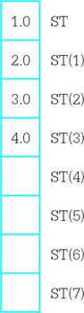
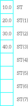
is coded in the data segment. Suppose that the floating-point register stack contains
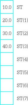
The left diagram below shows the resulting stack if fist intValue is executed and the right diagram shows the resulting stack if fistp intValue is executed. In both cases, the contents of intValue will be 0000000A, the doubleword length 2’s complement integer version of the floating-point number 10.0.
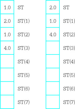
The situation is a bit more confusing when the destination is one of the floating-point registers. Suppose that at execution time the floating register stack contains
The left diagram below shows the resulting stack if fst st(2) is executed and the right diagram shows the resulting stack if fstp st(2) is executed. In the first case, a copy of ST has been stored in ST(2). In the second case, the copy has been made, and then the stack has been popped.
In addition to the load and store instructions listed above, the floating-point unit has an fxch instruction that will exchange the contents of two floating-point registers. With no operand,
fxch ; exchange ST and ST(1)
will exchange the contents of the stack top and ST(1) just below ST on the stack. With a single operand, for example,
fxch st(3) ; exchange ST and ST(3)
will interchange ST with the specified register.
Figure 10.4 shows the floating-point addition instructions. There are versions for adding the contents of ST to another register, contents of any register to ST, a real number from memory to ST, or an integer number from memory to ST. No version uses a BCD number. The faddp instruction pops the stack top after adding it to another register, so that both operands are destroyed.
|
Mnemonic |
Operand |
Action |
|---|---|---|
|
fadd |
(none) |
pops both ST and ST(1); adds these values; pushes sum onto the stack |
|
fadd |
st(num), st |
adds ST(num) and ST; replaces ST(num) by the sum |
|
fadd |
st,st(num) |
adds ST and ST(num); replaces ST by the sum |
|
fadd |
memory (real) |
adds ST and real number from memory; replaces ST by the sum |
|
fiadd |
memory (integer) |
adds ST and integer from memory; replaces ST by the sum |
|
faddp |
st(num),st |
adds ST(num) and ST; replaces ST(num) by the sum; pops ST from stack |
Figure 10.4: Floating-point addition instructions
A few examples illustrate how the floating-point addition instructions work. Suppose that the data segment contains the directives
 fpValue REAL4 5.0
 intValue DWORD 1
and that the floating-point register stack contains
After the instruction
fadd st,st(3)
is executed, the stack contains
Starting with these stack values, after the two instructions
 fadd fpValue
 fiadd intValue
are executed, the contents of the stack are
Finally, if the instruction
faddp st(2),st
is executed, the stack will contain
Subtraction instructions are displayed in Fig. 10.5. The first six instructions are very similar to the corresponding addition instructions. The second six subtraction instructions are the same except that the operands are subtracted in the opposite order. This is convenient since subtraction is not commutative.
|
Mnemonic |
Operand |
Action |
|---|---|---|
|
fsub |
(none) |
pops ST and ST(1); calculates ST(1) ST; pushes difference onto the stack |
|
fsub |
st(num), st calculates ST(num) ST; replaces ST(num) |
by the difference |
|
fsub |
st,st(num) calculates ST ST(num); |
replaces ST by the difference |
|
fsub |
memory (real) |
calculates ST −real number from memory; replaces ST by the difference |
|
fisub |
memory (integer) |
calculates ST −integer from memory; replaces ST by the difference |
|
fsubp |
st(num),st |
calculates ST(num) −ST; replaces ST(num) by the difference; pops ST from the stack |
|
fsubr |
(none) |
pops ST and ST(1); calculates ST −ST(1); pushes difference onto the stack |
|
fsubr |
st(num),st |
calculates ST −ST(num); replaces ST(num) by the difference |
|
fsubr |
st,st(num) |
calculates ST(num) −ST; replaces ST by the difference |
|
fsubr |
memory (real) |
calculates real number from memory −ST; replaces ST by the difference |
|
fisubr |
memory (integer) |
calculates integer from memory −ST; replaces ST by the difference |
|
fsubpr |
st(num),st |
calculates ST −ST(num); replaces ST(num) by the difference; pops ST from the stack |
Figure 10.5: Floating-point subtraction instructions
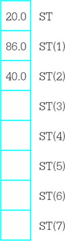
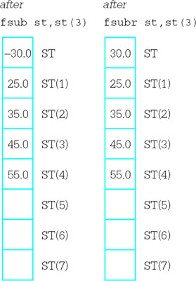
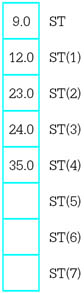
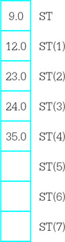
An example illustrates the difference between the parallel subtraction instructions. Suppose that the floating-point register stack contains
The two diagrams below show the results after executing the instructions fsub st,st(3) and fsubr st,st(3).
Multiplication and division instructions are listed in Figs. 10.6 and 10.7, respectively. Multiplication instructions have the same forms as the addition instructions in Fig. 10.4. Division instructions have the same forms as subtraction instructions in Fig. 10.5, that is, the R versions reverse the operands’ dividend and divisor roles.
|
Mnemonic |
Operand |
Action |
|---|---|---|
|
fmul |
(none) |
pops ST and ST(1); multiplies these values; pushes product onto the stack |
|
fmul |
st (num), st |
multiplies ST(num) and ST; replaces ST(num) by the product |
|
fmul |
st, st (num) |
multiplies ST and ST(num); replaces ST by the product |
|
fmul |
memory (real) |
multiplies ST and real number from memory; replaces ST by the product |
|
fimul |
memory (integer) |
multiplies ST and integer from memory; replaces ST by the product |
|
fmulp |
st (num), st |
multiplies ST (num) and ST; replaces ST (num) by the product; pops ST from stack |
Figure 10.6: Floating-point multiplication instructions
|
Mnemonic |
Operand |
Action |
|---|---|---|
|
fdiv |
(none) |
pops ST and ST(1); calculates ST(1) / ST; pushes quotient onto the stack |
|
fdiv |
st (num), st |
calculates ST(num) / ST; replaces ST(num) by the quotient |
|
fdiv |
st, st (num) |
calculates ST / ST(num); replaces ST by the quotient |
|
fdiv |
memory (real) |
calculates ST / real number from memory; replaces ST by the quotient |
|
fidiv |
memory (integer) |
calculates ST / integer from memory; replaces ST by the quotient |
|
fdivp |
st (num), st |
calculates ST (num) / ST; replaces ST (num) by the quotient; pops ST from the stack |
|
fdivr |
(none) |
pops ST and ST(1); calculates ST / ST(1); pushes quotient onto the stack |
|
fdivr |
st (num), st |
calculates ST / ST(num); replaces ST(num) by the quotient |
|
fdivr |
st, st (num) |
calculates ST(num) / ST; replaces ST by the quotient |
|
fdivr |
memory (real) |
calculates real number from memory / ST; replaces ST by the quotient |
|
fidivr |
memory (integer) |
calculates integer from memory / ST; replaces ST by the quotient |
|
fdivpr |
st (num), st |
calculates ST / ST (num); replaces ST (num) by the quotient; pops ST from the stack |
Figure 10.7: Floating-point division instructions
Figure 10.8 describes four additional floating-point instructions. Additional instructions that calculate tangent, arctangent, exponent, and logarithm functions are not covered in this book.
|
Mnemonic |
Operand |
Action |
|---|---|---|
|
fabs |
(none) |
ST := | ST | (absolute value) |
|
fchs |
(none) |
ST := – ST (change sign) |
|
frndint |
(none) |
rounds ST to an integer value |
|
fsqrt |
(none) |
replace the contents of ST by its square root |
Figure 10.8: Additional floating-point instructions
The floating-point unit provides a collection of instructions to compare the stack top ST to a second operand. These are listed in Fig. 10.9. Recall that the floating point has a 16-bit control register called the status word. The comparison instructions assign values to bits 14, 10, and 8 in the status word; these "condition code" bits are named C3, C2, and C0, respectively. These flags are set as follows:
|
Mnemonic |
Operand |
Action |
|---|---|---|
|
fcom |
(none) |
compares ST and ST(1) |
|
fcom |
st(num) |
compares ST and ST(num) |
|
fcom |
memory (real) |
compares ST and real number in memory |
|
ficom |
memory (integer) |
compares ST and integer in memory |
|
ftst |
(none) |
compares ST and 0.0 |
|
fcomp |
(none) |
compares ST and ST(1); then pops stack |
|
fcomp |
st(num) |
compares ST and ST(num); then pops stack |
|
fcomp |
memory (real) |
compares ST and real number in memory; then pops stack |
|
ficomp |
memory(integer) |
comparesSTandintegerinmemory;then popsstack |
|
fcompp |
(none) |
compares ST and ST(1); then pops stack twice |
Figure 10.9: Floating-point comparison instructions
 result of comparison C3 C2 C0
 ST > second operand 0 0 0
 ST < second operand 0 0 1
 ST = second operand 1 0 0
Another possibility is that the operands are not comparable. This can occur if one of the operands is the IEEE representation for infinity or NaN (not a number). In this case, all three bits are set to 1.
If a comparison is made in order to determine program flow, simply setting flags in the status word is no help. Conditional jump instructions look at bits in the flag register in the 80x86, not the status word in the floating-point unit. Consequently, the status word must be copied to memory or to the AX register before its bits can be examined by an 80x86 instruction, perhaps with a test instruction. The floating-point unit has two instructions to store the status word; these are summarized in Fig. 10.10. This table also shows the instructions for storing or setting the control word.
|
Mnemonic |
Operand |
Action |
|---|---|---|
|
fstsw |
memory word |
copies status register to memory word |
|
fstsw |
AX |
copies status register to AX |
|
fstcw |
memory word |
copies control word register to memory word |
|
fldcw |
memory word |
copies memory word to control word register |
Figure 10.10: Miscellaneous floating-point instructions
The 80x86 floating-point and integer units can actually execute instructions concurrently. Under certain circumstances this requires special care in assembly language programming. However, these techniques are not discussed in this book.
Exercises 10.1
- Suppose that a program’s data segment contains
 fpValue REAL4 0.5
 intValue DWORD 6
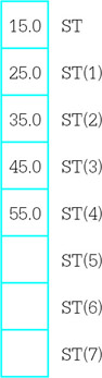
and that code executed so far by the program has not changed these values. Suppose also that the floating-point register stack contains
Assume that these values are correct before each instruction below is executed; do not use the "after" state of one problem as the "before" state of the next problem. Give the contents of the floating-point register stack of fpValue and of intValue following execution of the instruction.
- fld st(2)
- fld fpValue
- fild intValue
- fldpi
- fst st(4)
- fstp st(4)
- fst fpValue
- fistp intValue
- fxch st(3)
- fadd
- fadd st(3),st
- fadd st,st(3)
- faddp st(3),st
- fsub fpValue
- fisub intValue
- fisubr intValue
- fsubp st(3),st
- fmul st, st(4)
- fmul
- fmul fpValue
- fdiv
- fdivr
- fidiv intValue
- fdivp st(2),st
- fchs
- fsqrt
- Suppose that a program’s data segment contains
fpValue REAL4 1.5
intValue DWORD 9
and that code executed so far by the program has not changed these values. Suppose also that the floating-point register stack contains
Assume that these values are correct before each instruction below is executed. Give the contents of the status word flags C3, C2, and C0 following execution of the instruction.
- fcom
- fcom st(3)
- fcom fpValue
- ficom intValue
For the next two parts, also give the contents of the stack following execution of the instructions.
- fcomp
- fcompp
Programming with Floating Point Instructions
This section gives three examples of coding with floating-point instructions. The first is a program that calculates the square root of the sum of the squares of two numbers. Although we do not yet have any procedures to facilitate input/output of floating-point values, FPU operations can be viewed through Windbg. The second and third examples show procedure to facilitate input/output of floating-point numbers.
Figure 10.11 has a listing of the first example. Floating-point values are assembled at value1 and value2. The first instruction copies value1 from memory to ST. The second instruction copies it from ST to ST, pushing down the first stack entry to ST(1). The third instruction gives value1*value1 in ST, with "nothing" in ST(1). (Of course, there is always some value in each floating-point register.) The same sequence of instructions is repeated for value2. Figure 10.12 shows Windbg’s view of the CPU just before the second fmul is executed. At this point, there are copies of value2 in both ST and ST(1) and value1*value1 in ST(2). After the result is calculated in ST, it is stored in sqrt and popped from the stack, leaving the stack in its original state.
; find the sum of the squares of two floating-point numbers
; Author: R. Detmer
; Date: 4/98

.386
.MODEL FLAT

.STACK 4096 ; reserve 4096-byte stack

.DATA ; reserve storage for data
value1 REAL4 0.5
value2 REAL4 1.2
sqrt REAL4 ?
.CODE
_start:
 fld value1 ; value1 in ST
 fld st ; value1 in ST and ST(1)
 fmul ; value1*value1 in ST
 fld value2 ; value2 in ST (value1*value1 in ST(1))
 fld st ; value2 in ST and ST(1)
 fmul ; value2*value2 in ST
 fadd ; sum of squares in ST
 fsqrt ; square root of sum of squares in ST
 fstp sqrt ; store result

PUBLIC _start
END
Figure 10.11: Floating-point computations
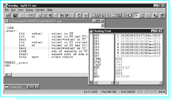
Figure 10.12: Execution of floating-point example
Notice that the value 1.2 is shown in Fig. 10.12 as 1.2000000476837158e+0000. The reason that there are nonzero digits after the decimal point is that 1.2 does not have an exact representation as a floating point number. The approximation used by the 32-bit REAL4 directive translates back to the number shown in 17-decimal-digit precision. You can get a better approximation by using a REAL8 or a REAL10 directive, but at the cost of extra bytes of storage.
The second example is an implementation of a simple ASCII to floating-point conversion algorithm. This algorithm, given in Fig. 10.13, is similar to the one used by the atoi and atod macros—it scans memory at the address given by its parameter, interpreting the characters as a floating point.
 value := 0.0;
 divisor := 1.0;
 point := false;
 minus := false;

 point at first character of source string;
 if source character = '-'
 then
 minus := true;
 point at next character of source string;
 end if;

 while (source character is a digit or a decimal point) loop
 if source character = '.'
 then
 point := true;
 else
 convert ASCII digit to 2's complement digit;
 value := 10*value + float(digit);
 if point
 then
 multiply divisor by 10;
 end if;
 end if;
 point at next character of source string;
 end while;

 value := value/divisor;

 if minus
 then
 value := -- value;
 end if;
Figure 10.13: ASCII to floating-point algorithm
This algorithm is implemented in a NEAR32 procedure atofproc. This procedure has one parameter—the address of the string. It returns the floating-point value in ST. No flags are set to indicate illegal conditions, such as multiple minus signs or decimal points. The code appears in Fig. 10.14.
; ASCII to floating-point code
; author: R. Detmer
; revised: 4/98

.386
.MODEL FLAT

PUBLIC atofproc

false EQU 0
true EQU 1

.DATA
ten REAL4 10.0
point BYTE ?
minus BYTE ?
digit WORD ?

.CODE

atofproc PROC NEAR32 ; convert ASCII string to floating-point number
; Parameter passed on the stack: address of ASCII source string
; After an optional leading minus sign, only digits 0-9 and a decimal
; point are accepted - the scan terminates with any other character.
; The floating-point value is returned in SP.

 push ebp ; establish stack frame
 mov ebp, esp
 push eax ; save registers
 push ebx
 push esi

 fld1 ; divisor := 1.0
 fldz ; value := 0.0
 mov point, false ; no decimal point found yet
 mov minus, false ; no minus sign found yet
 mov esi, [ebp+8] ; address of first source character


 cmp BYTE PTR [esi], '-' ; leading minus sign?
 jne endifMinus ; skip if not
 mov minus, true ; minus sign found
 inc esi ; point at next source character
endifMinus:

whileOK: mov bl, [esi] ; get next character
 cmp bl, '.' ; decimal point?
 jne endifPoint ; skip if not
 mov point, true ; found decimal point
 jmp nextChar
endifPoint:
 cmp bl, '0' ; character a digit?
 jl endwhileOK ; exit if lower than '0'
 cmp bl, '9'
 jg endwhileOK ; exit if higher than '9'
 and bx, 000fh ; convert ASCII to integer value
 mov digit, bx ; put integer in memory
 fmul ten ; value := value * 10
 fiadd digit ; value := value + digit
 cmp point, true ; already found a decimal point?
 jne endifDec ; skip if not
 fxch ; put divisor in ST and value in ST(1)
 fmul ten ; divisor := divisor * 10
 fxch ; value back to ST; divisor back to ST(1)
endifDec:
nextChar: inc esi ; point at next source character
 jmp whileOK
endwhileOK:

fdivr ; value := value / divisor
 cmp minus, true ; was there a minus sign?
 jne endifNeg
 fchs ; value := -value
endifNeg:
 pop esi ; restore registers
 pop ebx
 pop eax
 pop ebp
 ret 4
atofproc ENDP
 END
Figure 10.14: ASCII to floating-point conversion
This implementation of the ASCII to floating-point algorithm uses ST(1) for divisor and ST for value except for one short segment where they are reversed in order to modify divisor. After the procedure entry code, the instructions
 fld1 ; divisor := 1.0
 fldz ; value := 0.0
initialize these two variables. Note that the value 1.0 for divisor ends up in ST(1) since it is pushed down by the fldz instruction.
The design element
value := 10*value + float(digit);
is implemented by the code
 fmul ten ; value := value * 10
 fiadd digit ; value := value + digit
Note that a word-length 2’s complement integer version of digit is stored in memory. The floating-point unit takes care of converting it to floating point as part of the fiadd instruction.
To implement "multiply divisor by 10," the number to be multiplied must be in ST. The instructions
 fxch ; put divisor in ST and value in ST(1)
 fmul ten ; divisor := divisor * 10
 fxch ; value back to ST; divisor back to ST(1)
take care of swapping divisor and value, carrying out the multiplication in ST, and then swapping back.
When it is time to execute "value := value / divisor" the instruction
fdivr ; value := value / divisor
pops value from ST and divisor from ST(1), computes the quotient, and pushes it back to ST. Notice that the fdiv version of this instruction would incorrectly compute "divisor/value." After the division instruction, ST(1) is no longer in use by this procedure. The instruction fchs changes the sign of value if a leading minus sign was noted in the ASCII string.
You can test atofproc with a simple test driver program such as the one shown in Fig. 10.15. The "output" of the procedure can be viewed using Windbg.
 ; test drive for atofproc
 ; Author: R. Detmer
 ; Date: 4/98

 .386
 .MODEL FLAT


 ExitProcess PROTO NEAR32 stdcall, dwExitCode:DWORD
 EXTRN atofproc:NEAR32
 .STACK 4096 ; reserve 4096-byte stack


 .DATA ; reserve storage for data
 String BYTE "435.75", 0


 .CODE ; program code


 _start:
 pushd NEAR32 PTR String
 call atofproc
 INVOKE ExitProcess, 0
 PUBLIC _start
 END
Figure 10.15: Test driver for atofproc
Finally we come to a procedure to convert a floating-point parameter to "E notation." The procedure generates a 12-byte long ASCII string consisting of
- a leading minus sign or a blank
- a digit
- a decimal point
- five digits
- the letter E
- a plus sign or a minus sign
- two digits
This string represents the number in base 10 scientific notation. For example, for the decimal value 145.8798, the procedure would generate the string b1.45880E+02, where b represents a blank. Notice that the ASCII string has a rounded value.
Figure 10.16 displays the design for the floating to ASCII procedure. After the leading space or minus sign is generated, most of the work necessary to get the remaining characters is done before they are actually produced. The value is repeatedly multiplied or divided by 10 until it is at least 1.0 but less than 10.0. Multiplication is used if the value is initially less than 1; the number of multiplications gives the negative power of 10 required for scientific notation. Division is used if the value is initially 10.0 or more; the number of divisions gives the positive power of 10 required for scientific notation.
point at first destination byte;

if value ≥ 0
then
 put blank in destination string;
else
 put minus in destination string;
 value := -value;
end if;
point at next destination byte;

exponent := 0;
if value ≠ 0
then

 if value > 10
 then
 until value < 10 loop
 divide value by 10;
 add 1 to exponent;
 end until;
 else
 while value < 1 loop
 multiply value by 10;
 subtract 1 from exponent;
 end while;
 end if;
end if;
add 0.000005 to value; { for rounding }
if value > 10
then
 divide value by 10;
 add 1 to exponent;
end if;

digit := int(value); { truncate to integer }
convert digit to ASCII and store in destination string;
point at next destination byte;
store "." in destination string;
point at next destination byte;

for i:= 1 to 5 loop
 value := 10 * (value - float(digit));
 digit := int(value);
 convert digit to ASCII and store in destination string;
 point at next destination byte;
end for;
store E in destination string;
point at next destination byte;
if exponent ≥ 0
then
 put + in destination string;
else
 put - in destination string;
 exponent := -exponent;
end if;
point at next destination byte;

convert exponent to two decimal digits;
convert two decimal digits of exponent to ASCII;
store characters of exponent in destination string;
Figure 10.16: Floating-point to ASCII conversion algorithm
Only five digits are going to be displayed after the decimal point. The value between 1.0 and 10.0 is rounded by adding 0.000005; if the sixth digit after the decimal point is 5 or greater, this will be reflected in the digits that are actually displayed. It is possible that this addition gives a sum of 10.0 or more; if this happens, the value is divided by 10 again and the exponent is incremented.
With a value at least 1.0 but under 10.0, truncating to an integer gives the digit to go before the decimal point. This digit and the decimal point are generated. Then the remaining five digits can be generated by repeatedly subtracting the whole part from the value, multiplying the remaining fraction by 10, and truncating the new value to an integer.
After the "fraction" of the ASCII string is generated, the letter E, a plus or minus sign for the exponent, and the exponent digits are generated. The exponent will contain at most two digits—the single IEEE notation provides for numbers as large as 2128, which is less than 1039.
Figure 10.17 shows this design implemented in a procedure named ftoaproc. The procedure has two parameters: first, the floating-point value to be converted and second, the address of the destination string.
; floating point to ASCII code
; author: R. Detmer
; revised: 4/98

.386
.MODEL FLAT

PUBLIC ftoaproc
C3 EQU 0100000000000000b
C2 EQU 0000010000000000b
C0 EQU 0000000100000000b

.DATA

value REAL4 ?
ten REAL4 10.0
one REAL4 1.0
round REAL4 0.000005
digit WORD ?
exponent WORD ?
controlWd WORD ?
byteTen BYTE 10

.CODE
ftoaproc PROC NEAR32 ; convert floating-point number to ASCII string
; Parameters passed on the stack:
; (1) 32-bit floating point value
; (2) address of ASCII destination string
; ASCII string with format [blank/-]d.dddddE[+/-]dd is generated.
; (The string is always 12 characters long.)
 push ebp ; establish stack frame
 mov ebp, esp
 push eax ; save registers
 push ebx
 push ecx
 push edi

 fstcw controlWd ; get control word
 push controlWd ; save control word
 or controlWd, 0000110000000000b
 fldcw controlWd ; set control to chop
 mov edi, [ebp+8] ; destination string address
 mov eax, [ebp+12] ; value to convert
 mov exponent, 0 ; exponent := 0
 mov value, eax ; value to ST via memory
 fld value
 ftst ; value >= 0?
 fstsw ax ; status word to AX
 and ax, C0 ; check C0
 jnz elseNeg ; skip if set (value negative)
 mov BYTE PTR [edi], ' ' ; blank for positive
 jmp endifNeg
elseNeg: mov BYTE PTR [edi], '-' ; minus for negative
 fchs ; make number positive
endifNeg:
 inc edi ; point at next destination byte

 mov exponent, 0 ; exponent := 0
 ftst ; value = 0?
 fstsw ax ; status word to AX
 and ax, C3 ; check C3
 jne endifZero ; skip if zero
 fcom ten ; value > 10?
 fstsw ax ; status word to AX
 and ax, C3 or C2 or C0 ; check for all C3=C2=C0=0
 jnz elseLess ; skip if value not > 10
untilLess:
 fdiv ten ; value := value/10
 inc exponent ; add 1 to exponent
 fcom ten ; value < 10
 fstsw ax ; status word to AX
 and ax, C0 ; check C0
 jnz untilLess ; continue until value < 10
 jmp endifBigger ; exit if
elseLess:
whileLess:
 fcom one ; value < 1
 fstsw ax ; status word to AX
 and ax, C0 ; check C0
 jz endwhileLess ; exit if not less
 fmul ten ; value := 10*value
 dec exponent ; subtract 1 from exponent
 jmp whileLess ; continue while value < 1

endwhileLess:
endifBigger:
endifZero:
 fadd round ; add rounding value
 fcom ten ; value > 10?
 fstsw ax ; status word to AX
 and ax, C3 or C2 or C0 ; C3=C2=C0=0? (value > 10?)
 jnz endifOver ; skip if not
 fdiv ten ; value := value/10
 inc exponent ; add 1 to exponent
endifOver:

; at this point 1.0 <= value < 10.0
 fist digit ; store integer part
 mov bx, digit ; copy integer to BX
 or bx, 30h ; convert digit to character
 mov BYTE PTR [edi], bl ; store character in destination
 inc edi ; point at next destination byte
 mov BYTE PTR [edi], '.' ; decimal point
 inc edi ; point at next destination byte
 mov ecx, 5 ; count of remaining digits
forDigit: fisub digit ; subtract integer part
 fmul ten ; multiply by 10
 fist digit ; store integer part
 mov bx, digit ; copy integer to BX
 or bx, 30h ; convert digit to character
 mov BYTE PTR [edi], bl ; store character in destination
 inc edi ; point at next destination byte
 loop forDigit ; repeat 5 times
 mov BYTE PTR [edi], 'E' ; exponent indicator
 inc edi ; point at next destination byte
 mov ax, exponent ; get exponent
 cmp ax, 0 ; exponent >= 0 ?
 jnge NegExp
 mov BYTE PTR [edi], '+' ; non-negative exponent
 jmp endifNegExp
 NegExp: mov BYTE PTR [edi], '-' ; negative exponent
 neg ax ; change exponent to positive

endifNegExp:
 inc edi ; point at next destination byte
 div byteTen ; convert exponent to 2 digits
 or ax, 3030h ; convert both digits to ASCII
 mov BYTE PTR [edi+1], ah ; store characters in destination
 mov BYTE PTR [edi], al
 pop controlWd ; restore control word
 fldcw controlWd
 pop edi ; restore registers
 pop ecx
 pop ebx
 pop eax
 pop ebp
 ret 8
ftoaproc ENDP
 END
Figure 10.17: Floating point to ASCII conversion procedure
The program opens with directives that make it easy to refer to the control bits by name. The 1’s for C3, C2, and C0 are in positions 14, 10, and 8 respectively.
 C3 EQU 0100000000000000b
 C2 EQU 0000010000000000b
 C0 EQU 0000000100000000b
After normal procedure entry code, the FPU control word is copied to memory and then pushed on the stack so that it can be restored at the end of the procedure. Bits 10 and 11 of the control word are used for rounding control. The next two instructions set them to 11 so that a floating point to integer store will result in chopping of the fractional part of the number.
 fstcw controlWd ; get control word
 push controlWd ; save control word
 or controlWd, 0000110000000000b
 fldcw controlWd ; set control to chop
Most of the code in the procedure is a straightforward implementation of the design. However, the floating-point comparisons need some explanation. The first sequence is
 ftst ; value >= 0?
 fstsw ax ; status word to AX
 and ax, C0 ; check C0
 jnz elseNeg ; skip if set (value negative)
The ftst instruction compares value to 0, setting the flags in the status word. To test these bits, the status word is copied to AX. The C0 flag is set only when ST < 0. The and instruction masks all bits but the one corresponding to C0, and the jnz instruction branches if the remaining bit is nonzero, that is, the value is negative.
A similar but more complicated check comes when "value > 10" is implemented with
 fcom ten ; value > 10?
 fstsw ax ; status word to AX
 and ax, C3 or C2 or C0 ; check for all C3=C2=C0=0
 jnz elseLess ; skip if value not > 10
Since ST > operand results in all C3 = C2 = C0 = 0, all three control bits must be zero. The program masks with C3 or C2 or C0, a descriptive way of writing 0100010100000000. This or operation combines operands at assembly time, not at execution time.
Conversion of the exponent to two ASCII characters uses a slightly new technique. The exponent in AX is non-negative and less than 40 when the following code is executed.
 div byteTen ; convert exponent to 2 digits
 or ax, 3030h ; convert both digits to ASCII
 mov BYTE PTR [edi+1], ah ; store characters in destination
 mov BYTE PTR [edi], al
Dividing by 10 puts the quotient (the high-order base ten digit) in AL and the remainder (the low-order digit) in AH. These are simultaneously converted to ASCII by the or instruction, and are then stored in the destination string.
Programming Exercises 10.2
- Write a complete program that will prompt for and input a decimal value for the radius of a circle and will calculate and display (appropriately labeled) the circumference and the area of the circle. Use the input and output macros to input and output character strings, the atofproc and ftoaoproc procedures to convert between floating point and ASCII, and FPU instructions for floating-point operations.
- Write a NEAR32 procedure ftoaproc1 that will convert a floating-point number to an ASCII string in fixed point format. Specifically, the procedure must have four parameters pushed on the stack:
- a 32-bit floating point value
- the address of the destination string
- a word containing the total number n of characters in the string to be generated
- a word containing the number of digits d to be generated after the decimal point
The output string will consist of a leading blank or minus sign, the integer part of the value in n-d–2 positions (with leading blanks as needed), a decimal point, and the fractional part of the value rounded to d positions. The procedure will preserve all registers and will remove parameters from the stack.
- The following algorithm approximates the cube root of a real number x
root := 1.0;
until (|root -- oldRoot| < smallValue) loop
 oldRoot := root;
 root := (2.0*root + x/(root*root)) / 3.0;
end until;
Implement this design in a NEAR32 procedure cuberoot, using 0.001 for smallValue. Assume there is one parameter passed on the stack, the value of x. Return the result in ST. The procedure will preserve all registers and will remove parameters from the stack.
Write a short test driver for your procedure, viewing the results with WinDbg.
Floating Point Emulation
Some 80x86 computer systems have no floating-point unit. Such a system can still do floating-point arithmetic. However, floating-point operations must be performed by software routines using memory and the general purpose registers, rather than by a floating-point unit. This section describes procedures for multiplication and for addition of floating-point numbers. These could be useful for floating-point emulation, and they also provide a better understanding of the floating-point representation.
The procedures in this section manipulate floating-point values in the IEEE single format. Recall from Section 1.5 that this scheme includes the pieces that describe a number in "base two scientific notation":
- a leading sign bit for the entire number, 0 for positive and 1 for negative
- an 8-bit biased exponent (or characteristic). This is the actual exponent plus a bias of 12710
- 23 bits that are the fraction (or mantissa) expressed with the leading 1 removed
This is the format produced by the REAL4 directive.
Each procedure combines the components of its parameters to yield a result in the structure fp3. Often this result is not normalized; that is, there are not exactly 24 significant fraction bits. The NEAR procedure normalize adjusts the fraction and exponent to recover the standard format.
Notice that there is a problem representing the number 0.0 using the normal IEEE scheme. There is no "binary scientific notation" zero with a 1 bit preceding the binary point of the fraction. The best that can be done is 1.0 2 127, which is small, but nonzero. According to the rules given previously, this value would have an IEEE representation consisting of 32 zero bits. However, the two bit patterns that end with 31 zeros are considered special cases, and each is interpreted as 0.0 instead of plus or minus 1.0 −2 −127. These special cases will be considered in the following multiplication and addition code.
In addition to a special bit pattern to represent 0.0, the IEEE standard describes three other distinctive situations. The pattern
s 11111111 00000000000000000000000
(sign bit s, biased exponent 255, and fraction 0) represents plus or minus infinity. These values are used, for example, as quotients when a nonzero number is divided by zero. Another special case is called NaN (not a number) and is represented by any bit pattern with a biased exponent of 255 and a nonzero fraction. The quotient 0/0 should result in NaN, for example. The final special case is a denormalized number; when the biased exponent is zero and the fraction is nonzero, then no leading 1 is assumed for the fraction. This allows for representation of extra small numbers. Code in this section’s floating-point procedures looks for the special zero representations wherever needed. However, other special number forms are ignored.
We will frequently need to extract the sign, exponent, and fraction of a floating-point number. For this purpose we will use a macro expand. This macro will have four parameters
- a 32-bit floating point number
- a byte to hold the sign (0 for positive, 1 for negative)
- a word to hold the unbiased (actual) exponent
- a doubleword to hold the fraction, including the leading 1 for a nonzero number.
Code for the macro expand appears in Fig. 10.18.
 expand MACRO source, sign, exponent, fraction
 LOCAL addOne, endAddOne
 ; take the 32-bit floating-point value source and expand it into
 ; separate pieces:
 ; sign: byte
 ; exponent: word (bias removed)
 ; fraction: doubleword (with leading 1)
 push eax ; save EAX
 mov eax, source ; get source
 rol eax, 1 ; sign to bit 0
 mov sign, 0 ; clear sign
 mov sign, al ; get byte with sign bit
 and sign, 1 ; mask all but sign bit
 rol eax, 8 ; shift exponent to bits 0--7
 mov exponent,ax ;get word with biased exponent
 and exponent, 0ffh ; mask all but exponent
 sub exponent, 127 ; subtract bias
 shr eax, 9 ; shift fraction to right
 test eax, eax ; is fraction zero?
 jnz addOne ; add leading 1 bit if nonzero
 cmp exponent, --127 ; was original exponent 0?
 je endAddOne ;if so,leave fraction at zero
 AddOne: or eax, 800000h ; add leading 1 bit
 endAddOne:
 mov fraction, eax ; store fraction
 pop eax ; restore EAX
 ENDM
Figure 10.18: expand macro
The expand macro code illustrates how useful the bit manipulation operations can be. The sign bit is isolated by rotating it left to bit position 0, saving the byte containing it, and then masking by 1 (=00000001b) to zero all bits except the sign bit. Then the additional eight exponent bits are rotated to the right end of EAX and saved as a word before the leading bits are masked off. The bias of 127 is subtracted to get the true signed exponent. Finally the fraction is shifted back to the right of EAX. Before it is saved, a check for the IEEE 0.0 representation is made. If the original number was not 0.0, then the leading 1 bit of the scientific notation is inserted with the or operation.
The plan is to take floating-point numbers apart into their sign-fraction-exponent forms, implement an operation by manipulating the parts, and then combine the resulting sign-fraction-exponent pieces back into a floating-point result. The combine operation will also be done with a macro, called combine. Code for this macro appears in Fig. 10.19.
 combine MACRO destination, sign, exponent, fraction
 LOCAL endZero
 ; take the separate pieces:
 ; sign: byte
 ; exponent: word (bias removed)
 ; fraction: doubleword (with leading 1)
 ; of a floating-point value and combine them into a 32-bit
 ; IEEE result at destination
 push eax ; save EAX
 push ebx ; and EBX
 mov eax, 0 ; zero result
 cmp fraction, 0 ; zero value?
 je endZero ; skip if so
 mov al, sign ; get sign
 ror eax, 1 ; rotate sign into position
 mov bx, exponent ; get exponent
 add bx, 127 ; add bias
 shl ebx, 23 ; shift to exponent position
 or eax, ebx ; combine with sign
 mov ebx, fraction ; get fraction
 and ebx, 7fffffh ; remove leading 1 bit
 or eax, ebx ; combine with sign and exponent
 endZero:
 mov destination, eax ;store result
 pop ebx ; restore registers
 pop eax
 ENDM
Figure 10.19: combine macro
The design for the combine macro assumes that each of the pieces of representing a floating-point value is legal, with a zero fraction the only special case considered. With these assumptions, the fraction will be normalized; that is, bit 24 will be the one and no bit to the left will be one. The operations that we will do with floating-point representations may leave a non-normalized result. We need a third macro, this one to normalize a floating-point representation. The code is in Fig. 10.20. It implements the following design:
 normalize MACRO sign, exponent, fraction
 LOCAL endZero, while1, while2, endWhile1, endWhile2
 ; Normalize floating-point number represented by separate pieces:
 ; sign: byte
 ; exponent: word (bias removed)
 ; fraction: doubleword (with leading 1)
 push eax ; save EAX
 cmp fraction, 0 ; zero fraction?
 je endZero ; exit if so
 while 1: mov eax, fraction ; copy fraction
 and eax, 0ff000000h ; nonzero leading byte?
 jz endWhile1 ; exit if zero
 shr fraction, 1 ; shift fraction bits right
 inc exponent ; subtract 1 from exponent
 jmp while1 ; repeat
 endWhile1:
 while 2: mov eax, fraction ; copy fracton
 and eax, 800000h ; check bit 23
 jnz endWhile2 ; exit if 1
 shl fraction, 1 ; shift fraction bits left
 dec exponent ; subtract 1 from exponent
 jmp while2 ; repeat
 endWhile2:
 end Zero:
 pop eax ; restore EAX
 ENDM
Figure 10.20: normalize macro
if the fraction is zero then exit; end if;
while there is a non-zero bit in the left-hand byte of the fraction loop
 shift fraction bits one position to the right;
 add 1 to exponent;
end loop;
while bit 23 is not 1 loop
 shift fraction bits one position to the left;
 subtract one from exponent;
end loop;
Multiplication is the easiest floating-point operation to implement. It is based on the usual method of multiplying numbers in scientific notation:
- multiply the fractions to get the fraction of the result
- add the exponents to get the exponent of the result
- follow customary rules of signs to get the sign of the result
This method is implemented in the code displayed in Fig. 10.21. The procedure fMult-Proc has three parameters pushed on the stack—the two operands and the address for the result. The sign is computed with using an exclusive or of the operands’ signs. Addition of the exponents is straightforward. Multiplication of the fractions is followed by shifting off the low-order 23 bits; recall that each fraction is logically a 1, followed by a binary point, followed by 23 binary fraction bits. Multiplying two such fractions gives 46 fraction bits, and the extra 23 must be discarded.
; procedure fMultProc(Operand1, Operand2 : float;
; Result : address of float)
; parameters are passed in doublewords on the stack
; parameters are removed by the procedure
; author: R. Detmer 4/98

.DATA
sign1 BYTE ?
exponent1 WORD ?
fraction1 DWORD ?
sign2 BYTE ?
exponent2 WORD ?
fraction2 DWORD ?
sign3 BYTE ?
exponent3 WORD ?
fraction3 DWORD ?

.CODE
fMultProc PROC NEAR32
 push ebp ; save base pointer
 mov ebp,esp ; copy stack pointer
 push eax ; save registers
 push edx

 expand [ebp+16], sign1, exponent1, fraction1
 expand [ebp+12], sign2, exponent2, fraction2
 mov al, sign1 ; combine signs
 xor al, sign2
 mov sign3, al ; and save
 mov ax, exponent1 ; add exponents
 add ax, exponent2
 mov exponent3, ax ; and save
 mov eax, fraction1 ; multiply fractions
 mul fraction2
 shrd eax, edx, 23 ; discard extra bits
 mov fraction3, eax ; and save
 normalize sign3, exponent3, fraction3
 mov edx, [ebp+8] ; address for result
 combine [edx], sign3, exponent3, fraction3

 pop edx ; restore registers
 pop eax
 pop ebp ; restore base pointer
 ret 12 ; return, removing parameters
fMultProc ENDP
Figure 10.21: fMultProc procedure
The macros used by fMultProc are shown in previous figures. Although macros are convenient here, note that there are some dangers. You could not, for instance, use the statements
 mov eax, [ebp+8] ; address for result
 combine [eax], sign3, exponent3, fraction3
to combine the result pieces. The reason is that the combine macro uses the EAX register internally. It would have been safer to implement each of expand, combine, and normalize as procedures rather than macros.
Next we implement an algorithm for floating-point addition. This is somewhat more difficult than multiplication, but again follows the same sort of procedure that you would use to add two numbers in scientific notation, namely to adjust them to have the same exponent, and then add the fractions. One additional complication is that for a negative number, the fraction must be negated prior to adding it to the other fraction. The following algorithm is implemented in the code in Fig. 10.22.
; procedure fAddProc(Operand1, Operand2 : float;
; Result : address of float)
; parameters are passed in doublewords on the stack
; parameters are removed by the procedure
; author: R. Detmer 4/98

.DATA
sign1 BYTE ?
exponent1 WORD ?
fraction1 DWORD ?
sign2 BYTE ?
exponent2 WORD ?
fraction2 DWORD ?
sign3 BYTE ?
exponent3 WORD ?
fraction3 DWORD ?

.CODE
fAddProc PROC NEAR32
 push ebp ; save base pointer
 mov ebp,esp ; copy stack pointer
 push eax ; save registers
 push edx
 expand [ebp+16], sign1, exponent1, fraction1
 expand [ebp+12], sign2, exponent2, fraction2
 mov ax, exponent1 ; copy exponent1
while1: cmp ax, exponent2 ; exponent1 < exponent2?
 jnl endWhile1 ; exit if not
 inc ax ; add 1 to exponent1
 shr fraction1,1 ; shift fraction1 1 bit right
 jmp while1 ; repeat
endWhile1: mov exponent1, ax ; put fraction1 back in memory
 mov ax, exponent2 ; copy exponent2
 while2: cmp ax, exponent1 ; exponent2 < exponent1?
 jnl endWhile2 ; exit if not
 inc ax ; add 1 to exponent1
 shr fraction2,1 ; shift fraction2 1 bit right
 jmp while2 ; repeat
endWhile2: mov exponent2, ax ; put fraction2 back in memory
 mov exponent3, ax ; save common exponent
 cmp sign1, 1 ; sign1 = minus?
 jne notNeg1 ; skip if not
 neg fraction1 ; negate fraction1
notNeg1:
 cmp sign2, 1 ; sign1 = minus?
 jne notNeg2 ; skip if not
 neg fraction2 ; negate fraction2
notNeg2:
 mov eax, fraction1 ; add fractions
 add eax, fraction2
 mov fraction3, eax ; and save
 mov sign3, 0 ; plus
 cmp eax, 0 ; fraction3 < 0?
 jnl notNegResult ; skip if not
 mov sign3, 1 ; minus
 neg fraction3 ; make fraction3 positive
notNegResult:
 normalize sign3, exponent3, fraction3
 mov edx, [ebp+8] ; address for result
 combine [edx], sign3, exponent3, fraction3
 pop edx ; restore registers
 pop eax
 pop ebp ; restore base pointer
 ret 12 ; return, removing parameters
fAddProc ENDP
Figure 10.22: fAddProc procedure
expand each number into sign, exponent, and fraction components;
while exponent1 < exponent2 loop
 add 1 to exponent1;
 shift fraction1 one bit right;
end while;
while exponent2 < exponent1 loop
 add 1 to exponent2;
 shift fraction2 one bit right;
end while;
exponent3 := exponent1;
{the exponents are equal}
if sign1 = minus then negate fraction1; end if;
if sign2 = minus then negate fraction2; end if;
fraction3 := fraction1 + fraction2;
sign3 := plus;
if fraction3 < 0
then
 sign3 := minus;
 negate fraction3;
end if;
normalize sign3, exponent3, fraction3;
combine sign3, exponent3, fraction3 into result;
Programming Exercises 10.3
Each of the exercises below are to be programmed without using floating-point instructions.
- Write a NEAR32 procedure fDivProc that has three parameters, Operand1, Operand2, and Result. Each of the operands is a 32-bit floating point value and Result gives the address for a 32-bit floating-point result. If Operand2 ≠ 0.0, put the value of Operand1/Operand2 in the address given by Result. If the second operand is zero, then use the IEEE representation for plus or minus infinity as the result (plus or minus will depend on the sign of Operand1). The procedure will remove parameters from the stack and will change no register.
- Write a NEAR32 procedure fSubProc that has three parameters, Operand1, Operand2, and Result. Each of the operands is a 32-bit floating-point value and Result gives the address for a 32-bit floating-point result. Put the value of Operand1—Operand2 in the address given by Result. The procedure will remove parameters from the stack and will change no register. (Although you could do this by calling fAddProc, write a complete procedure instead.)
- Write a NEAR32 procedure fNegProc that has two parameters, Operand and Result. Operand is a 32-bit floating-point value and Result gives the address for a 32-bit floating-point result. Put the value of Operand1 in the address given by Result. The procedure will remove parameters from the stack and will change no register.
- Write a NEAR32 procedure fCmpProc that has two parameters, Operand1 and Operand2. Each of the operands is a 32-bit floating-point value. This procedure will compare the values of Operand1 and Operand2 and will return 0 in EAX if they are equal, 1 if Operand1 < Operand2, and +1 if Operand1 > Operand2. The procedure will remove parameters from the stack and will change no register other than EAX.
Floating Point and In line Assembly
High-level language compilers sometimes have the ability to translate a program that includes in-line assembly code. This permits most of a program to be written in the high-level language, while a few parts are written in assembly language. These parts may need critical optimization or may implement low-level algorithms that would be difficult or impossible to code in the high-level language.
This section contains a single example of a program that compiles using Microsoft Visual C++. It performs the same computations as does the code in Fig. 10.11, namely to find the square root of the sum of the squares of two floating-point values, However, this version provides for input of the values and output of the results, with the input and output done in C++. The code is shown in Fig. 10.23.
// square root of sum of squares of two values
#include
void main()
{
 float value1;
 float value2;
 float sum;

 cout << "First value? ";
 cin >> value1;
 cout << "Second value? ";
 cin >> value2;

 __asm
 {
 fld value1
 fld st
 fmul
 fld value2
 fld st
 fmul
 fadd
 fsqrt
 fstp sum
 }
 cout << "The sum is " << sum << endl;
}
Figure 10.23: In-line assembly code
Notice that for this compiler the in-line assembly language code is preceded by the __asm keyword that begins with two underscores, and that braces surround the assembly language statements. Notice also that the assembly language statements can reference variables declared in C++ statements. Finally, although these assembly language statements are floating-point instructions, almost any statements can appear in in-line assembly language, including those with labels.
Programming Exercises 10.4
- Write a complete program that will prompt for and input a decimal value for the radius of a circle and will calculate and display (appropriately labeled) the circumference and the area of the circle. Do the input and output with C++ and the floating-point calculations with floating-point instructions in in-line assembly.
- The following algorithm approximates the cube root of a real number x
root := 1.0;
until (|root -- oldRoot| < smallValue) loop
 oldRoot := root;
 root := (2.0*root + x/(root*root)) / 3.0;
end until;
Write a C++ program to declare variables, input a value for x, and display root. Implement the cube root algorithm with in-line assembly code, using 0.001 for smallValue.
Summary
The Intel 80x86 floating-point unit (FPU) contains eight data 80-bit data registers, organized as a stack. It executes a variety of instructions from load and store to arithmetic to complex transcendental functions. Comparison instructions set bits in a FPU status register; this status word must be copied to AX or to memory to check the outcome of a comparison.
Conversion between floating point and ASCII representations is similar to that previously done for integers. The easiest ASCII format to scan is a simple decimal format. The simplest ASCII format to produce is E-notation.
Floating-point instructions can be emulated without a floating-point unit. The basic techniques involve separating floating-point representations into sign, exponent, and fraction components, manipulating these components, and then combining the resulting components back into a floating-point representation.
Some high-level language compilers translate in-line assembly code. One application of this is with floating-point instructions, doing input/output in a language like C++ and computations in assembly language. However, in-line assembly is also useful in other critical or difficult to-implement applications.
Preface
- Representing Data in a Computer
- Parts of a Computer System
- Elements of Assembly Language
- Basic Instructions
- Branching and Looping
- Procedures
- String Operations
- Bit Manipulation
- The Assembly Process
- Floating-Point Arithmetic
- Decimal Arithmetic
- Input/Output
- Appendix A Hexadecimal/ASCII conversion
- Appendix B Useful MS-DOS Commands
- Appendix C MASM 6.11 Reserved Words
- Appendix D 80x86 Instructions (by Mnemonic)
- Appendix E 80x86 Instructions (by Opcode)
EAN: 2147483647
Pages: 113
