Change Propagation and Round Trip Engineering
Overview
When the ancient Greek philosopher Heraclitus said that "everything is in a state of flux," he was not thinking of data models, but he might as well have been. No matter how good the initial data model and the resulting physical schema, it is almost inevitable you will need to make at least some changes during the life of the database. Good initial modeling will minimize the overall need for changes, and lessen the severity of those changes, but you should still expect to make changes along the way.
Changes to data structures are disruptive, and can have a far reaching impact on existing applications, and the members of a software development team. To minimize this disruption, you need tools that allow you to manage change smoothly and reliably. VEA has some very good facilities for managing database changes.
Making changes at the conceptual level in your ORM source model(s), and then propagating those changes through the logical model and to the physical database schema is the most effective method. The next best alternative is to make changes directly in the logical model and generate them into the physical schema.
The worst alternative is to make changes in the physical database itself, and then update the logical and conceptual models. The toolset in VEA supports all these alternatives, and they'll all be discussed in this chapter. First, we'll discuss managing changes in the modeling environment, and then changes in the physical schema.
| Note |
Years of observation as a consultant have shown that even the most experienced designers are capable of making truly bone-headed decisions if they bypass the conceptual model when changing existing data structures. ORM conceptual models excel at exposing assumptions, and are easy to validate with users. Because changes usually come about as a result of newly discovered business requirements, changing the ORM model first makes a lot of sense. |
Mapping ORM Changes to Logical Models
Use the facts and constraints listed in Table 16-1 to create a small ORM source model that will be used for the example. The first column shows the fact type as you should type it into the fact editor. The second column shows how to answer the question on the Constraints tab of the Fact Editor. Except where specified, only answer Constraint Question #1 on the tab. The third column shows the verbalization of the constraint. Compare the text in the third column to the output of the Verbalizer window to ensure that you have applied the proper constraints.
|
Fact Type |
Fact Editor Constraint |
Constraint Verbalization |
|---|---|---|
|
Patient has Family Name |
Exactly One |
Each Patient has some FamilyName. |
|
Patient has PhoneNr |
Zero or One |
Each Patient has at most one PhoneNr. |
|
Patient was born in Country |
Zero or One |
Each Patient was born in at most one Country. |
|
Country has Country Name / Country Name belongs to Country |
Exactly One (question #1), Zero or One (question #2) |
Each Country has some CountryName. |
The graphical representation of your ORM model should look like Figure 16-1.
Assign the data types and lengths shown in Table 16-2 to the objects in your model. Save your model to a file called Patient_Simple_ORM.
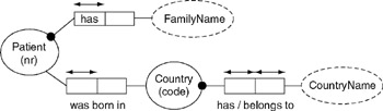
Figure 16-1: Graphical ORM model.
|
Model Object Type |
MS SQL Server Physical Data Type |
|---|---|
|
Country |
char(2) |
|
CountryName |
varchar(30) |
|
FamilyName |
varchar(30) |
|
Patient |
smallint |
|
PhoneNr |
varchar(14) |
Create an empty database model diagram and add Patient_Simple_ORM to the database project list. If necessary, refer to Chapter 7 for detailed instructions on building database projects with ORM source models. After building the database project you should have a small database model diagram that looks like Figure 16-2.
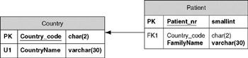
Figure 16-2: Logical Model.
Your column names may have slightly different names or be in a different order to that shown in Figure 16-2. Chapter 7 discusses controlling automatic column name generation from the ORM level, and Chapter 12 discusses renaming and re-ordering columns in the database model diagram. Save your database diagram model to a file called Patient_Simple_Build.
| Caution |
If you change a table or column name, or reorder any columns in the database model diagram, you will be prompted to migrate the changes back to the ORM source model. See Figure 10-26 at the end of Chapter 10 for a screen shot of the migration prompt and a more detailed explanation. |
Generate a physical database schema from the database model diagram Patient_Simple_Build. Generating physical schemas is explained in Chapter 11. For this exercise, do not create the schema through a DDL script, but instead use an ODBC connection. This physical schema will be used later in the chapter to demonstrate change management, so create the physical schema before proceeding with the following example.
- Save a backup copy of your models to an alternate subdirectory. This backup will preclude the need to start from scratch if you make a mistake that causes unexpected results.
- Assume you are creating the "Patient_Simple" data model for a hospital's information system. Some of the users just came forward with a new piece of information and a new requirement.
- (New Information) Thirty characters is not long enough for CountryName. A check of the ISO website shows that for the current list, the longest country name is 44 characters .
- (New requirement) The system must store a list of the patient's self reported drug allergies. Many patients don't report any allergies, while other patients report allergies to many drugs.
- To accommodate the information in item (2a) simply click on the CountryName object in your ORM model and edit the data type. Change the length from 30 to 44. Chapter 4 explains how to change data types in an ORM model.
- To accommodate the new requirement in item (2b), you must add a new fact type to the ORM source model that will allow the system to store information about patient drug allergies. The fact type and constraints are listed in Table 16-3.
Table 16-3: Drug allergy fact type. Fact Type
Fact Editor Constraint
Constraint Verbalization
Patient is allergic to Drug
Zero or More (question #1); Zero or More (question #2)
It is possible that some Patient is allergic to more than one Drug and that more than one Patient is allergic to some Drug.
- Adding the drug allergy fact type in the previous step automatically created a new object type called "Drug". Give this object type a reference mode of "Name", and assign it a physical data type of varchar(5). Clearly, five characters is too short for a drug name, but we'll fix this mistake later as part of the three-way synchronization process. Your modified ORM model should look like Figure 16-3.
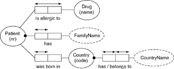
Figure 16-3: ORM model with new drug allergy fact. - Save the updated ORM source model and open the file Patient_Simple_Build.
- Choose Database > Project > Build from the main menu. If prompted to migrate changes back to the source, answer No .
Caution Under certain conditions, you may be prompted to migrate changes from the logical model to the ORM source model. As a general rule, answer No if this prompt appears while you are attempting to build a project.
Migrating changes from a database model diagram to an ORM source model means altering the ORM source model to the consistent with the database model diagram.
Usually, you are building a project because you just made changes to the ORM source model, thus temporarily causing the ORM model to be inconsistent with the existing database model diagram. If you answer Yes to the migrate question, VEA will push information from the old database model diagram back into the ORM source model, thus undoing the ORM changes that you just made.
The general rule of answering No only applies while building a project. For instance, when saving a logical database model diagram that you have just modified by renaming columns or tables, or adding trigger code, it makes sense to migrate changes back to the source model.
- The project build updated the length of the CountryName column from 30 to 44. The project build also created a new table, though it is not yet visible on the drawing surface.
- From the Tables and Views window, drag the new table out onto the drawing surface. Your database model diagram should now look like Figure 16-4. The names in your diagram may be different because of the name generation options you have chosen in the ORM model. CountryName is now 44 characters long, and the new table has the proper key structure to record a list of allergies for patients who report them.
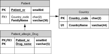
Figure 16-4: Result of a project build after changing the ORM model. - Rename the "Patient_allergic_Drug" table to "Patient_Drug_Allergy." Save the file Patient_Simple_Build. When prompted to migrate changes, answer Yes .
Migrating Logical Model Changes to ORM Models
Until now, the only changes you have migrated back from a database model diagram to an ORM source model have been name changes. However, you can also make actual structural changes in the database model diagram and migrate them back to the ORM model.
| Note |
Making structural changes in the database model diagram and migrating them back to the ORM source model is like eating soup with a fork. You can do it, but it's messy. It is much better to make the changes at the conceptual ORM level and push them down into the database model diagram through a project build. Try to limit your changes in the database model diagram to things that can be done only at the logical level, like writing triggers and procedures, creating views, renaming tables etc. Even most column names can be controlled from the ORM name generation rules, although some columns must be explicitly renamed at the logical level. |
Generally, the bigger the change at the logical level, the uglier the migrated result will be in the conceptual model. The conceptual ORM level contains more semantic information than the logical level of the database model diagram. You can always go from a state of greater information to lesser information, as occurs during a project build. When going from the logical to the conceptual level, some of the information is simply not available.
For instance, ORM supports a verbalized predicate for every relationship, regardless of whether the objects involved will become tables or columns at the logical level. However, at the logical level, predicate information is available only for relationships between tables. Logical information that does not originate at the ORM level is thus tagged with ugly "placeholder" predicates.
ORM also provides more than one way to model certain situations, even though the end logical result is the same. This is a great advantage in creating understandable data models that can be validated with users. However, when pushing logical information up into ORM, Visio has to arbitrarily choose an ORM modeling technique, whether or not it is well suited to the particular situation.
The simplest way to understand these issues is to go through an example. Make a copy of the backup ORM source model that you created at the beginning of section 16.2. Do not use the model that you used in section 16.2, and do not use your actual backup model. Call the copy Copy_Patient_Simple_ORM.
- Create an empty database model diagram. Add the ORM model Copy_ Patient_Simple to the project list and build the project. When prompted to save the database model diagram, name the file Copy_Patient _Simple_Build.
- The database model diagram that you just built should look like Figure 16-2.
- In the database model diagram, use the editing tools to build the Patient_Drug_Allergy table. Make sure to add the foreign key. Your database model diagram should look like.
- Figure 16-4 with the exception of the table name.
- Save the database model diagram and answer Yes when prompted to migrate changes back to the source model.
- Open up the ORM model (Copy_Patient_Simple_ORM). The drawing pane will look exactly as it did before. However, you will notice two new fact types in the Fact Types pane of the Business Rules window. If you don't see the Business Rules window, choose Database > View > Business Rules from the main menu.
- Drag the new fact types (they both contain the word "Patient_Drug_Allergy) onto the drawing surface. The result is shown in Figure 16-5.
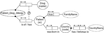
Figure 16-5: ORM model after migrating a table from the logical level.
The new object type Patient_Drug_Allergy corresponds to the table you created in step three. The object type uses an external primary reference constraint, which is explained in section 5.2 of Chapter 5. Figure 16-5 and Figure 16-3 are conceptually equivalent, but Figure 16-3 is a more natural expression of the facts, and easier to interpret. You can make Figure 16-5 easier to read by putting meaningful words in the predicates of the new fact types.
Updating Physical Schemas with Logical Model Changes
Regardless of how you make changes to your logical database model diagram, those changes must be propagated into the physical database schema. For this example, we'll use the ORM source model and the generated database model diagram from section 16.2
You generated a physical in Section 16.2 prior to changing the length of the CountryName object, and prior to adding the drug allergy fact type. In this example, you'll use VEA's Update Wizard to update the physical schema with the changes you made to your model.
- Open the file Patient_Simple_Build.
- From the main menu choose Database > Update to invoke the Update Wizard (Figure 16-6). By default the Generate a text and Detect Changes check boxes are selected. Select the Update Database checkbox as well. Click the Next button.
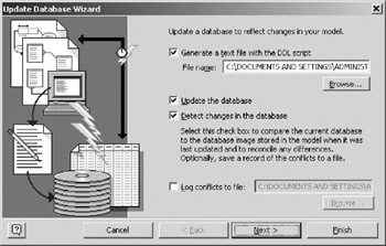
Figure 16-6: Update Wizard, page one. - On the second page (Figure 16-7), highlight the DSN that you used to first create the physical schema in section 16.2, and click Next . You'll be asked to furnish logon credentials for your database (Figure 16-8). Depending on how your DSN is defined, either supply a username and password or leave the fields blank and click OK.
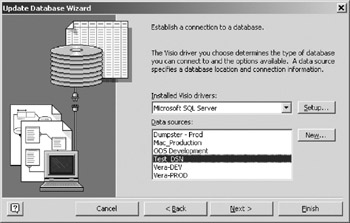
Figure 16-7: Update Wizard, page two.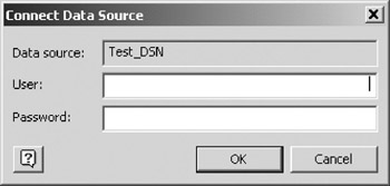
Figure 16-8: Database Connection Prompt. - Once you have successfully connected, VEA displays a message saying that it is comparing the physical schema with the reverse engineered model. You may find this message a little confusing, since you have not yet specifically asked VEA to reverse engineer the physical database. However, VEA did extract an image of the database immediately after you first generated the physical schema in section 16.2. When the compare is finished, you should see a screen like Figure 16-9.
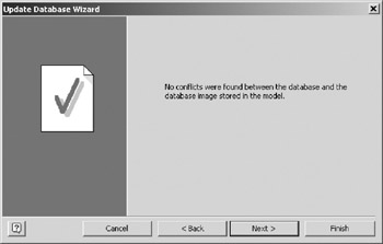
Figure 16-9: Update wizard page three, no conflicts.How can there be "no conflicts" when you know for a fact that the physical schema doesn't have the new Patient_Drug_Allergy table, and that CountryName in the physical schema is only 30 characters long instead of the new 44 characters ?
The message "no conflicts" does not refer to a comparison between the physical schema and the current model, but between the physical schema and an image of the last known state of the physical schema, which VEA extracted and stored in the current model during the initial physical schema generation. Because the physical schema has not been changed since the initial generation, it matches VEA's database image, and there is no conflict. This comparison will be explained further in section 16.6.
- Page four of the update wizard (Figure 16-10) shows a list of the model changes that are about to be generated into the database. This list gives the user a last chance to confirm that the changes are correct before updating the database. Click Next to continue.
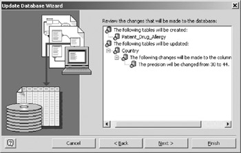
Figure 16-10: Ready to make changes to the physical schema. - VEA will validate the model for platform specific rules and report the results in the final page of the update wizard (Figure 16-11). Click Finish to update the database.
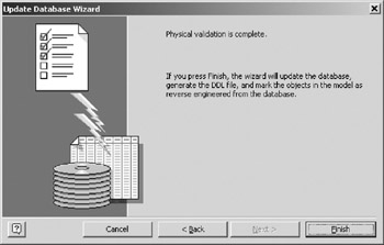
Figure 16-11: Update wizard, page five. - View the generated SQL script (screen shot not shown), and save the script to something other than the default filename . You will need to look at the script for the discussion of data migration in section 16.8.
- Use SQL Server Enterprise Manager to verify that the physical database has been changed.
Refreshing Logical Models with Physical Schema Changes
VEA's "Refresh" feature allows modelers to capture changes that were made at the physical database level and automatically incorporate them into the model. You will find it more effective to change a physical schema by first changing the logical model and then propagating the change to the physical schema. As it is, people in even the most disciplined environments make physical schema changes that bypass the data model.
To show the refresh feature in action, we must first introduce some changes into the physical schema of which the logical model is unaware. Let's simulate a situation where somebody changed the length of one column, and added an entirely new column without telling the data modeler:
- Using SQL Server Enterprise Manager , change the length of the FamilyName column in the Patient table from 30 to 35.
- Using SQL Server Enterprise Manager , add a column called PhoneNr to the Patient table. Assign the column a data type of varchar(14), and make the column nullable.
To refresh the database model diagram, follow these steps:
- Choose Database > Model > Refresh from the main menu.
- Connect to your database using the DSN that you used in the previous example.
- VEA compares the current physical schema with its stored image of the last known state of the physical schema. The image was last stored in the model during the update that you performed in section 16.4. In that image, FamilyName was defined as varchar(30), and PhoneNr did not exist, leading to a conflict in the Patient table as shown in Figure 16-12.
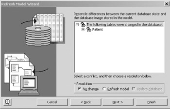
Figure 16-12: Refresh Wizard conflicts, tree collapsed . - Expanding the tree in the conflict listing (Figure 16-13) shows that there are actually two conflicts, the new PhoneNr column, and the changed length for the existing column FamilyName .

Figure 16-13: Refresh Wizard conflicts, tree expanded. - The wizard allows you to resolve conflicts on an individual basis, or en masse. To resolve an individual conflict, highlight it and select the Refresh model radio button. To resolve a group of conflicts, highlight the root node for that group and choose the Refresh model radio button. When you choose the Refresh model radio button, the question marks will disappear for the resolved conflicts, as shown in Figure 16-14.
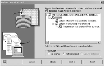
Figure 16-14: Choosing to refresh the logical model. - The final page of the refresh wizard (Figure 16-15) gives you chance to confirm changes before updating the logical model. Click Finish to update the database model diagram.
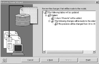
Figure 16-15: About to update the model. - Your database model diagram now includes the column PhoneNr in the Patient table, and the column FamilyName has been lengthened as shown in Figure 16-16.
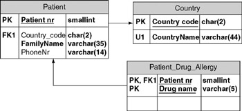
Figure 16-16: Refreshed database model diagram. - Save the database model diagram, and when prompted to migrate changes, answer Yes . This migration will "push" the new PhoneNr object and the updated FamilyName length back into the ORM source model.
- If you wish to confirm the migration, open the ORM source model, right click on the Patient object, and choose Show Relationships from the context menu. The graphical representation of the new fact "Patient has PhoneNr" will be automatically placed on the diagram.
Three Way Synchronization
From the previous two sections, it may appear that the Update Wizard is designed solely to propagate model changes to the physical schema, while the Refresh Wizard is designed to propagate changes from the physical schema back to the logical model. Actually, the Update Wizard can handle bi-directional changes in a single operation. This operation is known as three-way synchronization .
One may reasonably ask, "If the wizard is synchronizing the physical schema and the logical model, why is it called ˜three-way synchronization' instead of ˜two-way synchronization ?" Perhaps a more accurate description would be "three way comparison, yielding two way synchronization". To reliably synchronize the model and the physical schema, VEA must compare three things: The previous state of the physical schema (which should match the previous state of the logical model), the current state of the logical model, and the current state of the physical schema.
Synchronization involves managing the transition of multiple objects from one state to another. As long as the physical schema cannot be changed through means other than the Update Wizard, things are straightforward. Assuming a newly created model, here is the sequence of steps:
- Use the Generate Wizard to create a physical schema from the model. The physical schema and the model are both in state A.
- Modify your model. The model is in a new state (call it M for modified).
- Use the Update Wizard to change the physical schema. Via its database driver and an ODBC DSN, the tool issues DDL commands to change the state of the physical schema from state A to state M.
However, the physical schema can be changed through other means. Let's insert a step 2.5 and assume that someone made changes to the physical schema using database administration tools. Now the physical schema is not in state A, but in an unknown state X.
If, in step four, the tool merely issues DDL based upon the transition from state A to state M, the results will be unpredictable. The DDL might work if state X is not too much different from state A, or the DDL may fail completely. Even if the DDL succeeds, the physical schema will still not be in state M, but in some new state that is a mix of state M and state X. Worse, the new mixed state may break applications that depend on the database. No one will know exactly what the new state is, so fixing theproblem will be very difficult. Reliable synchronization requires the model to comprehend the physical schema's full state just prior to synchronization.
The solution is for VEA to compare the physical schema's current state (X) with physical schema's previous state A, which is also the previous state of the logical model. Conflicts between state X and state A must be resolved by adjusting the physical schema, the model, or both. Only after all conflicts are resolved so that the model fully comprehends the physical schema can the tool issue the appropriate commands to reliably synchronize the schemas.
Figure 16-17 shows a graphical representation of the major steps.
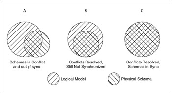
Figure 16-17: Resolving conflicts and synchronizing Schemas.
In step A of Figure 16-17, the physical schema has information that is unknown to the logical model and vice versa. Upon conflict resolution in step B, the logical model knows everything about the physical schema, though the physical schema may not fully comprehend the logical model. With the conflicts resolved, the tool can issue the proper DDL to reliably synchronize the physical schema with the logical model (step C).
There is one big problem with this solution: The critical comparison of the previous physical schema and logical model state (A) and the current physical schema state (X) cannot be done because state A no longer exists. The physical schema is in state X and the model is in state M. Visio avoids this problem by storing an image of state A in the model immediately after it first generates the physical schema. Now that all the pieces are in place, here is the new sequence of steps:
- Use the Generate Wizard to create a physical schema from the model. The physical schema and the model are now both in state A.
|
1.5 |
VEA extracts an image of state A from the physical schema and stores the image in the model file. |
- Modify your model. The model is now in state M, but the stored image remains in state A.
|
2.5 |
Someone else changes the physical schema. The physical schema is now in state X. |
- Invoke the Update Wizard to change the physical schema.
|
3.5 |
The Update Wizard compares state A and state X and reports all conflicts. For each conflict, you choose to either update the model or to update the physical schema. The logical model now fully comprehends the state of the physical schema. |
|
3.6 |
Through its database driver and an ODBC DSN, the tool issues DDL commands to synchronize the physical schema with the logical model. |
|
3.7 |
As a final step, VEA automatically extracts an image of the new physical schema, and replaces the stored image of state A with this new image. VEA is now ready for the next time you use the Update Wizard. |
Now that you've slogged your way through the abstract example of three-way synchronization, let's see it in action. Since you just refreshed your model, it is in the same state (call it state A) as the physical schema. VEA has stored an image of state A in your model:
- Use SQL Server Enterprise Manager to modify the physical schema.
- Drop the table Patient_Drug_Allergy .
- Lengthen the column Patient.PhoneNr from 14 to 20 characters .
The physical schema is now in state X.
- Now modify your model:
- In section 16.2, you purposely made the data length for the Drug object too short. Correct this "mistake" by changing the physical data type of the Drug object from varchar(5) to varchar(30) in the ORM source model.
- You decide that FamilyName should only have a length of 30 after all. Change the length in the ORM source model from 35 to 30.
- Rebuild the project to get an updated database model diagram. (If you are prompted to migrate changes, remember the general rule about not migrating changes when building a project). The logical model is now in state M, but the stored image is still in state A.
- Invoke the Update Wizard by choosing Database > Update from the main menu. Your screen should look like Figure 16-6. Select the Update Database checkbox and click the Next button.
- Highlight the appropriate DSN, and connect to your database. See Figure 16-7 and Figure 16-8 for screenshots.
- VEA compares the original state of the physical schema and logical model (A) with the new state of the physical schema (X), and reports the conflicts. In Figure 16-18, the tree has been expanded to show the detail.
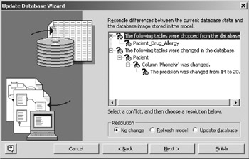
Figure 16-18: Database conflicts. - Assume that the lengthening of PhoneNr from 14 to 20 was correct, but that the dropping of the Patient_Drug_Allergy was incorrect. You thus want to update the model to reflect the longer length for PhoneNr but you want to put the dropped table back into the physical schema.
- Highlight the node that that says The precision was changed from 14 to 20 (under the node that says Column ˜PhoneNr was changed) and select the Refresh model radio button (Figure 16-19). The question marks next to the codes dealing with changes to the patient table are replaced with icons of documents, indicating that you have elected to resolve this conflict by updating your model. Question marks remain for Patient_Drug_Allergy because this conflict is still unresolved .
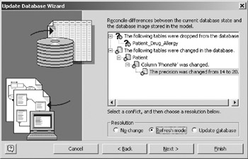
Figure 16-19: Refresh the model for the PhoneNr change of length. - Highlight the node that says Patient_Drug_Allergy and select the Update Database radio button (Figure 16-20). The question marks are replaced with database icons, indicating that you have chosen to resolve this conflict through a database update. Click the Next button
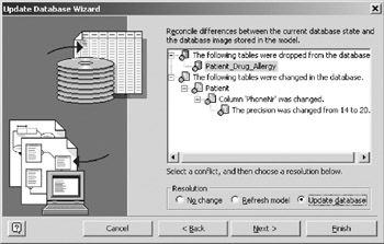
Figure 16-20: Update the database with the Patient_Drug_Allergy table.
- Highlight the node that that says The precision was changed from 14 to 20 (under the node that says Column ˜PhoneNr was changed) and select the Refresh model radio button (Figure 16-19). The question marks next to the codes dealing with changes to the patient table are replaced with icons of documents, indicating that you have elected to resolve this conflict by updating your model. Question marks remain for Patient_Drug_Allergy because this conflict is still unresolved .
- The next page of the wizard confirms the changes that will be made to the model. In Figure 16-21 the tree has been expanded to make the detail visible. Click Next to update the model and continue. Your logical model now fully comprehends the physical schema (you just reached step B in
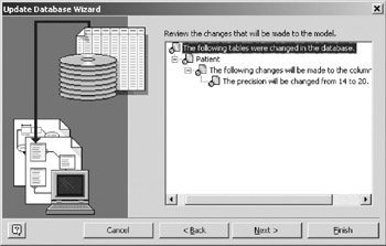
Figure 16-21: Update Wizard model update confirmation. - Figure 16-17.)
- The wizard can now issue the proper commands to synchronize the physical schema with the logical model. Figure 16-22 shows the changes that will be made to the database.
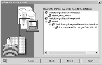
Figure 16-22: Update Wizard physical database update confirmation.
Note that you made changes only to the ORM source model and, yet the tool will issue commands to the database to actually create a table. The three-way synchronization feature recognized that the table Patient_Drug_Allergy had been dropped from the physical level. Instead of trying to change a non-existent object, the Wizard issues a CREATE TABLE statement. Click Finish and your physical schema will be synchronized with your logical model. Remember to save your logical model and answer Yes to the migration question.
Code Synchronization and Transfer
When you create a physical schema from your logical model (see chapter 11), VEA automatically produces the DDL necessary for creating tables and views. However, most databases provide their own procedural language for writing functions and procedures. You can write stored procedures to enforce constraints that cannot be handled by key structures, or to enforce business rules.
Contrary to the advice of many web application design books and self proclaimed application design experts, executing business logic in stored procedures is often an excellent idea. Writing business logic in stored procedures does not violate n- tier architecture, and well written procedures will not become "entangled" with the database.
It is important to keep business logic in a separate layer, but the physical place where that logic resides is not a guiding principal of n-tier architecture. Instead of executing all business logic in a physically separate application tier that must constantly query and write to the database as it processes business logic, it often makes sense write those rules into procedures right on the database. The application server merely supplies the correct arguments while invoking the procedure. All the heavy lifting is done by code that has local access to the data in a secure environment on a very powerful machine.
Even if you don't buy into the concept of using stored procedures to enforce business rules, over time you will end up writing significant amounts of code for things like archive triggers, complex views and the like. The VEA Synchronization and Transfer features can help you manage your code.
Code Synchronization
Thankfully code synchronization has nothing to do with three-way synchronization, so the explanation will be much simpler, and it won't require any diagrams.
Many organizations tightly manage the database code written by their database administrators and developers. In these workplaces, any database code must first be put into a script that follows standard formats and tested for accuracy. Once the script is known to work, it is stored under source code control. Often, the basic DDL is separated from the trigger and procedure code.
This extra management work may sound bureaucratic, but it often makes a lot of sense. Moving among environments (development, test, and production) is much easier and less error prone if all the objects are scripted first. Restoring after a crash or setting up another environment is much easier if different versions of the scripts are clearly identifiable. As a side effect of these policies, you often have to provide trigger and procedure scripts in separate files that can be managed apart from the main data model.
The need to keep your code in separate files can lead to a quandary : On the one hand, your database code needs to reside in separate files, and on the other hand, the most natural place to store and work on your code is in the modeling tool. Code synchronization and mirror files and solve this issue.
A mirror file is a plain-text file that resides outside your model. You associate the mirror file with database code objects in VEA. Once the mirror file and database code object are associated, VEA will synchronize the mirror file and database code object on demand. The synchronization can go in either direction, file to code object, or code object to file. Let's take a look at an example:
- If it isn't already running, open your Patient_Simple_Build file.
- If you don't see the Code window at the bottom of the screen, select Database > View > Code from the main menu.
- Click the New button in the Code window (Figure 16-23) to open the code editor.
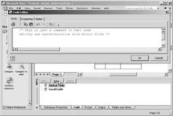
Figure 16-23: Invoking the code editor. - Put anything in the textbox on the Body pane of the editor. You don't have to write a real procedure to see how mirroring and code synchronization work.
- Switch to the Properties pane of the code editor (Figure 16-24). Provide a name for your code object in the Name text box. For this test, the Type doesn't matter, so accept the default choice. Put a file name in the Mirror file text box. Notice that the mirror file name and the name of the code object are completely independent, making it easy to adhere to file naming standards even if they differ from database object naming standards. Click OK to close the code editor
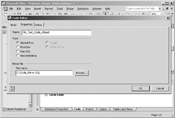
Figure 16-24: Code editor properties pane. - So far you have specified the mirror file but not created it. To actually create the file, choose Database > Code > Synchronize from the main menu to invoke the code synchronization window (Figure 16-25). Highlight the code object you just created and click the Update Mirror Files button. The first time you click this button the mirror file will be created and populated with the body of your code object. Subsequent clicks will merely update the existing file. The Update Model Now button copies the contents of the associated mirror file into the body of the code object. Both operations completely overwrite the target.
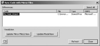
Figure 16-25: Code synchronization window. - As soon as you click one of the Update buttons , the list on the synchronization window will be replaced by a message (Figure 16-26). The list on the synchronization window is only populated with code objects whose body differs from the content of their mirror files. If you make a change to the code object or its mirror file, that object should be automatically put back on the list. The Refresh button forces VEA to look at all code objects and mirror files. Keep this model open for the next example.
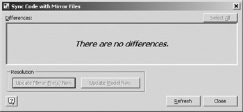
Figure 16-26: Code synchronization window after sync operation.
Code Transfer
Use this feature if you must have the same data model support more than one server. In most work situations, this single model, multiple back end scenario would be extremely rare.
Code objects are tied to the default VEA database driver. If you change from say, the MS SQL Server drive to the Oracle Server driver, your code objects will "disappear." The code objects will still be in the model, they are just not available with the alternate driver. This makes sense, because Oracle PL/SQL code is significantly different from TSQL.
VEA gives you the option to selectively copy (or move if you so desire ), code objects from one environment to another. Let's say you are re-hosting an Oracle database onto MS SQL Server. You might start by reverse engineering the existing database and all the procedure and trigger code. You would then switch to the MS SQL Server driver to adapt the tables. However, once you switched drivers, you would notice that all the trigger and procedure code stayed with the Oracle driver, and is not available to you.
Using Code Transfer, you can copy the Oracle code into the MS SQL Server version of the model. From that point, you can keep the code separate and work on converting the Oracle code to SQL Server. Fortunately, the Code Transfer feature is a lot easier to use than it is to explain, so let's take a look:
- While still in your model from the previous example, change the default VEA database driver by choosing Database > Options > Drivers from the main menu. Highlight the Oracle Server selection and click OK (Figure 16-27).
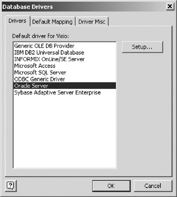
Figure 16-27: Changing Drivers to Oracle. - Look in the Code window to confirm that your code object has "disappeared."
- Invoke the Code Transfer window by choosing Database > Code > Transfer from the main menu.
- Highlight MS SQL Server in the Source DBMS text box and Oracle Server in the Destination DBMS text box. (Figure 16-28). Choose the Copy radio button in the upper right corner. Click OK to make the transfer
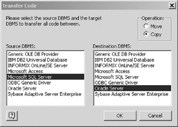
Figure 16-28: Code transfer window. - Your code object is now transferred, and looking in the Code window will confirm it.
| Note |
Remember three important points when using Code Transfer:
|
Data Migration
It's time to dig out the DDL script that you saved in step seven of section 16.4. As you recall, you generated that script the first time you used the Update Wizard to propagate a change from the logical model to the physical schema. The script modified the existing country table by lengthening the column from 30 to 44 characters . If you can't find the script on your computer, don't despair, because the salient portion is reproduced in Figure 16-29. To save space, the "go" command and extra blank lines between each SQL statement have been removed.
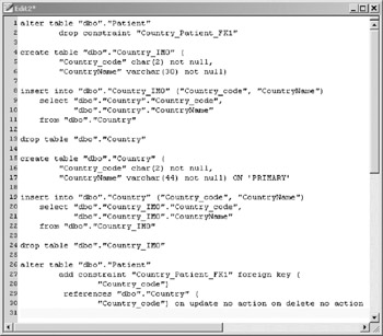
Figure 16-29: Fragment of a change script.
The purpose of this script is to modify a column in an existing table. Some database engines allow a column to be lengthened by a simple ALTER TABLE statement, but some engines require that the table be dropped and rebuilt with the new desired column length. The VEA tool is not tied to a specific database engine, so the designers have chosen to have the script drop and re-create the table, which will work with any database server. The VEA generated script is designed to preserve any data in the existing table.
Lines one and two of the script drop the foreign key constraint in the Patient table that points to Country Lines four through eleven of the script create a backup table called Country_IMO and insert the rows from the current table into the backup table.
Line 13 drops the current table. The DROP TABLE statement would have failed if the foreign key were not removed from the Patient table in lines one and two. Lines 15 through 22 create a new Country table with the correct data length for CountryName, and insert the rows from the backup table. Line 24 drops the backup table because it is no longer needed. Finally, the foreign key in the Patient table is restored in line 31.
VEA's automatic data migration can save you a lot of work, but there are some important caveats to remember:
- Be careful when performing this operation on large tables.
- VEA makes an exact copy of the table, and duplicates each existing row in the backup table. If the existing table has millions of rows, there is a good chance you will run into disk space issues on the server during the INSERT . If you are working in the middle of the night, you may have to page a data base administrator (DBA), and s/he will not be happy with you. You'll be tempted to make up a story about "unknown processes" bringing down the server, but don't do it. The DBA will find out the truth anyway and you'll be branded a "reckless liar" instead of just "reckless."
- Even if the server has plenty of disk space, the account with which you connect may be restricted in such a way as to make the insert fail. Heavy restrictions on your account are more likely if you have been branded a "reckless liar" in the past.
- If you add mandatory ( NOT NULL ) columns to existing tables, there are special considerations for the INSERT statement that restores the backup data into the new table.
- The new table now has a not null column for which there is no backup data. In these cases, VEA will insert the literal value ˜I for numeric and textual columns, which will work fine. For date columns, VEA will insert the result of a date function in the column.
- If the target column is the subject of a unique index, the INSERT statement that restores the backup data will fail. The only way around this is to make the changes via script instead of ODBC connection. Remove the unique index from the script and put the index on later, when you can get the real data.
- If the new column is mandatory and a foreign key, you need to do some preparation prior to running the update. You have a few choices to handle this situation.
- Edit the script to remove the NOT NULL qualification for the new column. Also remove the code that uses a literal value in the INSERT statement. Run the DDL. Update the table with real data when available, and then restore the NOT NULL constraint.
- Manually insert a row in the "parent" table that has ˜I as its primary keyso that the INSERT of the child row will succeed. This is the only method that will still allow you to use an ODBC connection and bypass the script.
- Edit the script to either remove or disable the foreign key constraint that covers the target column. The INSERT of the literal value will then work. After you UPDATE the table with real data, restore the foreign key.
DDL Script vs Automated Update
With the exception of the last section, this chapter has focused on making updates via a direct connection to the database, instead of running DDL scripts. Using a direct connection can save you a lot of time, but remember: Speed Kills!
There are many cases where using a script is preferable to an automated update. First among these cases are any changes to a production database. Using any type of automated tool that issues DDL to modify the schema of a production database is very risky. Only software salesman and outplacement consultants trying to drum up new business will tell you differently.
Always use a script that you have thoroughly tested to modify a production database. It goes without saying that you do the modifications during a planned time when the database will be unavailable to users. You should also consider writing a "back out" script that will restore the database to its original state if something goes wrong with your changes.
Modifications to Production are not the only concern. Even changes in the Development environment can benefit from scripting. While you are making the actual modifications to the physical schema in the Development environment, software coding has to stop. For most projects, this means two to ten people will not work during the changes. A well executed schema change should take only minutes, but problems can turn those minutes into hours. Ten people wasting half a day is an expensive proposition. Using a script that you have thoroughly tested is a good way to guarantee that the changes go smoothly and quickly.
VEA can generate new database scripts without ever connecting a database, but to generate scripts for modifying a database, VEA must connect to a server. On the surface, it appears that you cannot benefit from VEA's Update Wizard technology without letting the tool update your database automatically.
Actually, there's great news. It's quite easy to set up things so that the Update Wizard generates all your change scripts, but you still execute the scripts yourself after testing. All you need in MS SQL Server terms is two small databases, called "Model" and "Scratch." The equivalent Oracle term for what you need is "account."
Once you have set up your new databases (or accounts), follow these steps:
- VEA will never connect to anything but the Model database. When working on your model, use the Update Wizard and an ODBC connection to manage your physical schema.
- When the first version is of your schema is ready, use VEA to generate a DDL script of the schema.
- Run the script in the (empty) Scratch environment as a test.
- When satisfied with step 3, run the script in Development and Test. In larger shops , you can give the script to dba and s/he will run it. The dba can also modify the script to account for different physical sizing in Development and Test.
- When make additions or changes to data model, don't allow the Update Wizard to actually modify the schema in the Model database until you get agreement from the developers that the new model is correct.
- Once you have the agreement, use the Update Wizard to update your schema via an ODBC connection to the Model database. Have VEA produce an SQL script when is makes the changes. This script is your schema modification script.
- Export the schema from the Development environment. If the database has only a small amount of data, include the data in your export.
- Clean out the Scratch database.
- Import the Development schema into the empty Scratch database.
- (Conditional) If you had to export the Development schema without data, you must put representative data into the Scratch database. An empty schema is not a good test. Some modification scripts will succeed with an empty schema, but fail with a populated one.
- Run the script you created in step 6 against the Scratch environment.
- If you experience any problems, repeat steps 8 “ 11 until the script runs perfectly and gives the correct results.
- Agree on a 15 minute window during which everyone will stay out of the schema in the Development environment.
- Run the perfected script against the schema in the development environment. If you did your testing properly, you'll always stay well within the 15 minute window.
- Repeat steps 5 through 13 for subsequent changes.
These steps may seem somewhat involved, but the actual execution is very smooth and quick. The biggest advantages are:
- The Update Wizard writes the basic change scripts for you, saving a lot of work.
- You retain the safety, flexibility, and reproducibility of scripted changes.
- All testing occurs in steps (8 through 11) that don't affect anyone else.
- Most importantly, you know that script will work when you run it in step 13, because you have tested it thoroughly.
Overview of Database Modeling and the Database Modeling Tool
The Conceptual Modeling Solution (ORM)
- Object Types, Predicates, and Basic Constraints
- ORM Constraints
- Configuring, Manipulating, and Reusing ORM Models
- Mapping ORM Models to Logical Database Models
- Reverse Engineering and Importing to ORM
- Conceptual Model Reports
The Logical Modeling Solution (ER and Relational)
- Creating a Basic Logical Database Model
- Generating a Physical Database Schema
- Editing Logical Models”Intermediate Aspects
- Editing Logical Models”Advanced Aspects
- Reverse Engineering Physical Schemas to Logical Models
- Logical Database Model Reports
Managing Database Projects
EAN: 2147483647
Pages: 150
