Editing Logical Models”Advanced Aspects
Editing Logical Models Advanced Aspects
Copying Model Elements
Each logical model element such as a table scheme or foreign key relationship occurs only once in the underlying model. However, you can display as many copies as you like of the same model element on the diagram, on the same page or on different pages.
One reason to display multiple copies of a model element on the same page is to provide a cleaner layout of foreign key relationships. An easy way to copy a diagram instance of a table on the same page is to Control-drag it to another place on the diagram. To do this, select the table shape on the diagram, then hold the Ctrl key down as you drag a copy of it to the new position using the mouse.
Although the diagram displays two different copies of the table, both copies denote the same underlying table in the model. If you make a change to one (e.g. change its name ) this change is immediately reflected in the other copy. When you copy table shapes this way, the foreign key relationships on that table are not redisplayed. If you want to display those relationships on the copy, right-click the table copy and choose Show Related Tables from the context menu.
An alternative way to redisplay a table is to drag it onto the page from the Table and Views window . If this window is not open, you can open it by choosing Database > View > Tables and Views from the main menu. This is also the only way to display a table shape on a page where no instance of it is yet displayed. When you copy table shapes in this way, all the foreign key relationships on it are redisplayed as well. You can hide any duplicated relationship lines by deleting them from the diagram (not the model).
If you drag and drop a table on a different page, you can then add other tables to that page and the tool will draw the appropriate relationships between them. In this way, you can have different drawing pages that repeat tables as needed.
| Caution |
If you want to remove a table from a page, do not use the "cut" option. Instead make sure your option for delete is set to "ask the user what to do." Select the table and press the delete key. You will be asked if you want to delete the table from the drawing. Choose NO . This has no impact on other pages, nor does it remove the table from the model. If you performed a "cut" it will be removed from all pages and the model. |
In Figure 13-1, the Store table was dragged onto the drawing page as a duplicate. The foreign key relationship lines are duplicated between Store and State, and between Store and Invoice. We manually applied a fill color of yellow (this appears shaded in monochrome prints) to the duplicated table to indicate it is a duplicate on the drawing. To apply a fill color to a shape , right-click it, choose Format > Fill from the context menu, and then select the desired fill color. If the formatting toolbar is displayed, you can also apply the fill by clicking the Fill Color icon. This is a normal Visio feature.
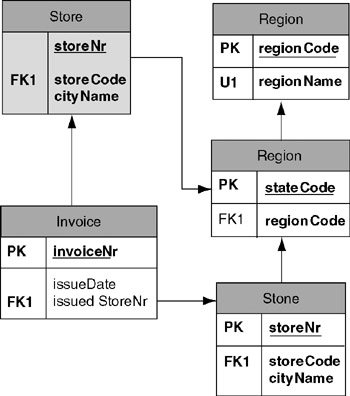
Figure 13-1: An extra copy of the Store table has been dragged onto the page.
Color is useful in many cases to indicate information about a table. For example, you can use different colors to indicate major tables, reference data tables, intersection tables for many-to-many relationships, or duplicate tables.
If you select a duplicated foreign key relationship and press the delete key, the Delete prompt dialog appears as shown in Figure 13-2.
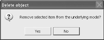
Figure 13-2: Deletion prompt.
Choose No. If you say "Yes," then the relationship is removed from the model, not the merely the drawing. Do the same for the other connection. The diagram will now appear as shown in Figure 13-3. Often, on a drawing page, it is difficult to prevent line entanglements. By placing a duplicate copy of the table on the page and by hiding selected relationships you can untangle the mess.
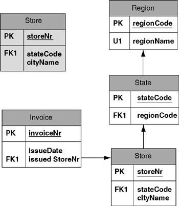
Figure 13-3: Page with some relationships hidden but not deleted.
Cloning Model Elements
It is also possible to clone a model element . Cloning creates a new model element (not just a shape) based on an existing one. When created, the clone has the same model properties as the original, except for the name . To clone a model element that is displayed on a diagram page, select the element, press Ctrl+C to copy it to the clipboard, then move the mouse cursor to the position (on the same page or a different page) where you wish to display the clone, and press Ctrl+V to paste the clone there. Instead of Ctrl+C, you can use the main menu option Edit > Copy . Instead of Ctrl+V, you can use the menu option Edit > Paste .
Each clone of a table is assigned the name of the original table, appended by a number that indicates the order in which it has been cloned from the original. For example, if you copy the Store table to the clipboard and paste it, this results in the clone table Store1. If you now copy the Store1 table to the clipboard and paste it, this results in the clone Store11. If instead you copy Store to the clipboard and paste it twice, this results in the clones Store1 and Store2.
A clone table initially has the same model properties as the original, except for its name. If you later make a change to the original (e.g., add a column), this change is not propagated to the clone. Similarly, if you later make a change to the clone, this change is not propagated to the original. This is because the original and the clone correspond to different underlying model elements.
If you select objects from one model, open a new or existing model, and paste the selection into that model, all the selected tables, relationships and associated code will be copied into that model. This is useful for model reuse. Although database projects may include multiple ORM source models, the version of VEA used at the time of writing has only limited support for the inclusion of multiple ER source models in the same project.
Database Properties Definition and Notes
To open the Database Properties dialog for a shape, simply select the shape. In the case of a foreign key relationship, the Definition category displays the names of the related table columns . The names should comply with your standard naming conventions. If you are using naming from an ORM model, most of these names will be defined using your defined naming convention available in ORM models (see Chapter 8).
The Database Properties dialog for tables includes a Notes category. Notes are very important for understanding the model. If you use an ORM drawing as a source to the model, the notes from the ORM model are copied as comments to the logical model. Notes are printed in model reports and provide context for reviews of the model. It is useful to create a template that you can copy into the notes area and then add the specific information. Some suggested notes sections are: Owner, Date Recorded, Steward, Source Document, Source System, and Description. The more consistent you make the template for the different element types, the more useful is your documentation. You can also hyperlink from objects to other documentation (see Chapter 17).
Check Clauses
In Chapter 12, we defined check clauses using the value constraints window. Here we create check clauses using the code editor. Check clauses are assigned either to a column or to a table. If the check clause involves more than one column, it must be specified at the table level. To create a check clause on a table, select the table then select Check Clauses from the database properties. To create a check clause on a column, you may select the Edit option for the column and then open the Check pane. When the Code Editor dialog appears, give the check clause a name under the Properties tab and then select the Body tab (Figure 13-4).
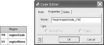
Figure 13-4: Code Editor Code Name ”Type Check Clause.
Within the body, enter the check clause code using the syntax appropriate for your DBMS. Figure 13-5 shows a simple example for declaring a list of possible values for the regionCode column.
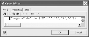
Figure 13-5: Enter the Check Clause Code.
In the following generated SQL Server code fragment, the check clause is applied to the appropriate column within the table. There are two distinct check clauses for this table.
create table "Region" (
"regionCode" char(2) not null constraint "RegionregionCode_Chk" check ("regionCode" in
 ('N','S','E','W','C')),
"regionName" varchar(20) not null constraint "RegionregionName_Chk" check ("regionName"
 in ('North','South','East','West','Central')))
go
Indexes
The Database Category Index is used to define unique or non-unique indexes on table columns . First, select the table to receive the index, then select New . The Create Index window is then displayed. It always appears as a non-unique index that can be changed later in the process. Enter the index name , and then select OK . The example creates a non-unique index on the Invoice Issue Date.
The next window allows you to select the column(s) for the index. Highlight the column on the left and select "Add" until you have selected all the required columns for the index. You can also rename or delete the index. The options button is for extended properties that only apply to SQL Server.
Designate the index type from the index Type drop-down box.
The Extended Index Attributes (Figure 13-9) define several index management parameters. If the index is clustered then the rows in the physical database match the primary key order. The STATS_NORECOMPUTE option prevents outdated index statistics from being recomputed. The Drop Existing option causes the index to be dropped and rebuilt. The Fill factor controls the how full an index page can be. The PAD_INDEX determines how full intermediate levels can become. The combination of the FILL_FACTOR and the PAD_INDEX affects index performance. Refer to SQL Server tuning documentation to determine the best setting for specific indexes (this topic is not covered in this text).
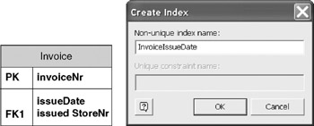
Figure 13-6: Creating an index on the Invoice Table named "InvoiceIssueDate."
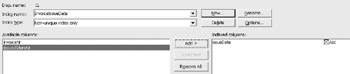
Figure 13-7: Index column selection.
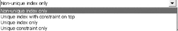
Figure 13-8: Index types.
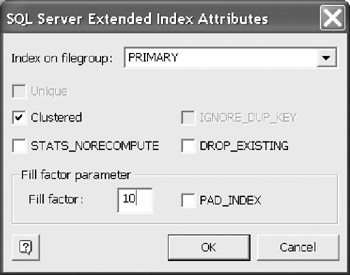
Figure 13-9: Index extended properties.
Triggers
The code window permits the creation and editing of several code types. These include Stored Procedure, Trigger, Check, Raw DDL, and View. Views were discussed in Chapter 12.
To open the code window for any type of code, select Database > View > Code from the main menu. For all the code examples that follow, the same code window is displayed. The difference is in the type of code. These options are not shown with each code example. However as you can see in Figure 13-10, the code type is determined by selecting the appropriate radio button. Select the Trigger option in the Database Category list and then select "Add." The code editor window opens with the Trigger Option selected. Enter a name for trigger and then select the "Body" tab.
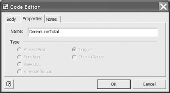
Figure 13-10: Setting the Trigger Name.
| Caution |
When defining these options you must give the code block a name. However, this name is not included in the CREATE statement. For example, you must include the " CREATE PROCEDURE LineTotal sp " as part of your code when in the Body pane of the Code Editor, even though you named the code "LineTotal_sp." |
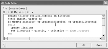
Figure 13-11: Trigger Code to compute the line Total.
Enter the trigger code. In this example, the lineTotal is to be recomputed if the quantity or unitPrice has been updated. Notice that trigger name "DeriveLineTotal." This name is not automatically inserted into the code. Therefore, you must enter the create trigger line in the code block.
Stored Procedures
Stored procedures are often DBMS specific. From the code editor, indicate the type of code is Stored Procedure and enter the procedure name . Figure 13-12 shows an example.
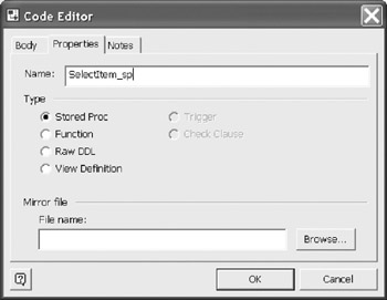
Figure 13-12: Starting a Stored Procedure.
The body of the stored procedure code is shown in Figure 13-13. Notice the Create Procedure "name" was entered. It is not derived from the name automatically.
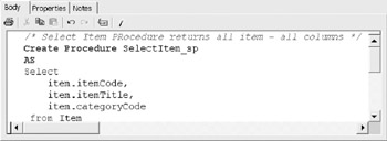
Figure 13-13: Stored Procedure.
Raw DDL
Select the Raw DDL code type to author any DDL syntax to include in the generate script. For example, you may include user permission syntax, user definitions and user roles. The following is a simple example of using raw DDL to create a default value. This code example establishes a default region code. The region code is also part of a check clause, therefore the value must also be a member in the set of legal values. The code window is not shown here, but it is the same code window as for any code type.
USE Sales
 GO
 CREATE DEFAULT RegionCodeDefault AS 'N'
The syntax must be valid for the target DBMS. If you select a different DBMS during a generate operation, the code may become invalid.
User Defined Functions
The following is a sample of the function to compute Line Total. This is another option for creating the value. This example was shown elsewhere as trigger code.
CREATE FUNCTION Line Total (@quantity int, @unitPrice money)
 RETURNS Money AS
 BEGIN
 RETURN (@quantity * @unitPrice)
 END
Here is the definition of a test table to demonstrate the defined function usage:
Create table Test (
 quantity int,
 UnitPrice money,
 lineTotal As dbo.LineTotal(quantity, unitPrice))
The following test of the function produces the results: quantity = 2, unit price = 3.00, line total = 6.00.
insert into Test (quantity, unitPrice) values (2,3.00)
 select * from Test
User Defined Types
User defined data types are based on the DBMS's built-in data types. A user defined data type has its own specific name. This name may be used to provide consistency for column data types in different tables. For example, the data type InvoiceNumber may be defined as small integer. Then when assigning the data type to the column InvoiceNr the data type can be declared as InvoiceNumber rather than smallint.
You can display the basic data types for the selected DBMS of the model by selecting Types from the main menu ( Database > View > Types ). All user defined types are built upon these basic types (Figure 13-14).
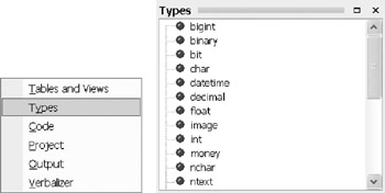
Figure 13-14: Menu selection and a partial list of SQL 2000 data types.
To add a user defined type, choose Database > User Defined Types from the main menu. Select Add to begin the definition. Enter a name for your new data type (Figure 13-15). The Copy From option permits you to copy one user defined type from another user defined type. Since there are no other defined data types at this time, the list is empty. It would seem natural that you could copy from the DBMS defined data types, but that is not the case. After entering the name, select "OK".
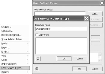
Figure 13-15: Defining the Invoice Number data type.
Now define the type based on the natural DBMS data types. Here InvoiceNumber is defined as numeric, small, signed integer (Figure 13-16). Once defined, this data type can be assigned to any InvoiceNr columns as a valid data type.
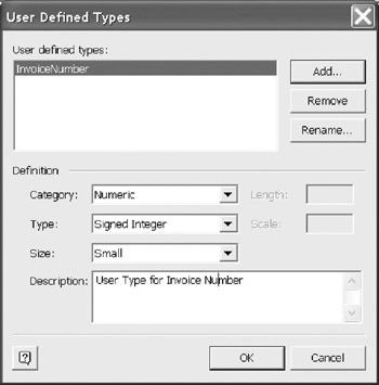
Figure 13-16: Setting User defined data type.
For this example, the following code will be added to the top of the generated DDL script. This must be loaded into the script prior to using the user defined data type. The DDL generation automatically places user defined data types prior to create table statements.
/* Add, update user defined datatype. */
 sp_addtype "InvoiceNumber", "smallint"
Extended Properties
Extended properties may be used to define where tables or images are stored. To add an extended property to a table, select the Extended category in its Database Properties sheet, and press the Edit button. If you are using SQL Server, the extended attributes dialog now appears (Figure 13-17).
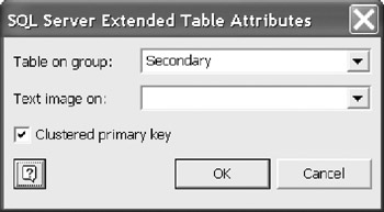
Figure 13-17: Extended properties option for SQL server.
Primary is the default group , which indicates the tables are stored in the Primary space definition. The DBA may assign several spaces for the database. It is here you can make the assignment. The Text Images can also be stored in a defined space in this example.
In this example (Figure 13-17), the LineItem table was selected and placed in the Secondary group. The generated DDL code for this example is shown below.
create table "LineItem" (
 "invoiceNr" smallint not null,
 "lineNr" tinyint not null,
 "quantity" tinyint not null,
 "itemCode" varchar(10) not null,
 "unitPrice" money not null,
 "lineTotal" money null) ON 'Secondary'
The Object Relational Stencil
The Object-Relational stencil is introduced here, but not discussed in detail. When you open an ER Source or Database Model Diagram solution, an Object-Relational stencil appears in the shapes window along with the ER stencil. To display the Object-Relational stencil shapes , simply click its title bar (Figure 13-18).
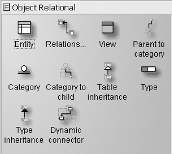
Figure 13-18: Object-Relational stencil. Also opens with the normal ER stencil.
This stencil includes three new icons for modeling: Table inheritance, Type, and Type inheritance (Figure 13-19). The three special icons provide additional support for object relational features supported in a few DBMSs such as Oracle 8 or higher, or IBM DB2 Universal Database. You can use this stencil for normal entity relationship modeling as well.
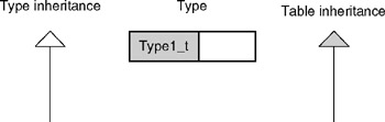
Figure 13-19: Type inheritance, Type, and Table inheritance icons.
Many DBMSs, including Microsoft Access and Microsoft SQL Server, do not currently support these object relational features. For such DBMSs, you should ignore the Object-Relational stencil completely .
| Caution |
Do not use the table inheritance feature as an alternative to the Parent-to-Child category relationship feature supported in the ER stencil. These features have completely different semantics, and should not be confused . Never use table inheritance in Microsoft SQL Server or Microsoft Access, as such usage may cause severe problems. |
Even if your DBMS does support object-relational features, we recommend that you ignore the Object-Relational stencil unless you have a compelling reason to use object-relational features. Currently, the object-relational solution in VEA is far less robust than the ER solution, mainly because it has rarely been used in practice, so comparatively little attention has been given to its support issues.
If you are familiar with object-relational features, the Type icon is used to create a set of columns that can be implemented within a single column of the associated table column. The Type inheritance connection is used to form this association. The Table inheritance connector is used for the same purpose, except a table is used in the association. Use these features only with an object-relational database, and only as a last resort.
Overview of Database Modeling and the Database Modeling Tool
The Conceptual Modeling Solution (ORM)
- Object Types, Predicates, and Basic Constraints
- ORM Constraints
- Configuring, Manipulating, and Reusing ORM Models
- Mapping ORM Models to Logical Database Models
- Reverse Engineering and Importing to ORM
- Conceptual Model Reports
The Logical Modeling Solution (ER and Relational)
- Creating a Basic Logical Database Model
- Generating a Physical Database Schema
- Editing Logical Models”Intermediate Aspects
- Editing Logical Models”Advanced Aspects
- Reverse Engineering Physical Schemas to Logical Models
- Logical Database Model Reports
Managing Database Projects
EAN: 2147483647
Pages: 150
- Chapter III Two Models of Online Patronage: Why Do Consumers Shop on the Internet?
- Chapter VIII Personalization Systems and Their Deployment as Web Site Interface Design Decisions
- Chapter XI User Satisfaction with Web Portals: An Empirical Study
- Chapter XIV Product Catalog and Shopping Cart Effective Design
- Chapter XVI Turning Web Surfers into Loyal Customers: Cognitive Lock-In Through Interface Design and Web Site Usability
