Reverse Engineering Physical Schemas to Logical Models
Using the Reverse Engineer Wizard
A physical database may be reverse engineered to either an ORM model or to a logical model. Reverse engineering to ORM was covered in Chapter 8 and enforces stricter model checking rules than are required for reverse engineering to a logical model. If the ORM reverse engineering process fails, you may still be able to reverse engineer the database to a logical model.
We now discuss reverse engineering to a logical database model. This process requires an ODBC connection, which may already exist or can be created from within the reverse engineering wizard. Creating this connection is not discussed in depth here, because it has been covered in detail in Sections 8.1 and 11.4. A wizard guides you through the reverse engineering process. If the process succeeds, the result is a logical ER model corresponding either to the whole of the physical database schema, or that portion of it that was selected to reverse engineer.
To reverse engineer an existing database, open a new instance of the Database Model Diagram solution and choose Database > Reverse Engineer from its main menu (Figure 14-1). This opens the Reverse Engineering Wizard.
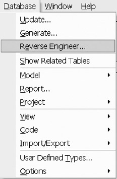
Figure 14-1: Drop-down menu for database- related actions.
If you are reverse engineering into an ER Source Model, the Reverse Engineering Option is located in the same menu, but it is the first selection, and there are fewer options in that list.
Create the Database Connection
The opening window of the Reverse Engineer Wizard lists the available data sources for you to reverse engineer. In our worked example, two SQL Server data sources already exist (see Figure 14-2). Here PATIENT EXAMPLE is a data source for an SQL Server database generated from a logical model similar to the Patient_LS model considered in earlier chapters.
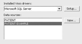
Figure 14-2: List of ODBC data sources.
If a data source for your database is not in the list, you will have to create the connection definition at this time. Select New and follow the ODBC Connection wizard.
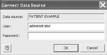
Figure 14-3: Database Logon.
This ODBC wizard is used in many products and is the same here. See Sections 8.1 and 11.4 for detailed instructions on how to do this. Within the ODBC definition the setup option is used to select the appropriate driver. For example, if you are connecting a SQL Server 2000 database, select SQL Server as the driver. Because there are several drivers in the list, be sure to check the type of connection and the version. There is more than one driver version for SQL Server, Oracle, and several others. The selection of the version is important for the proper transformation in either forward or reverse engineering where the DDL script syntax may differ . After creating the connection you are returned to this form to select the connection, with your new data source added to the list.
To make the ODBC connection to the physical database, select the relevant data source, then click Next . In the Connect Data Source dialog, provide the appropriate database logon to establish the connection (Figure 14-3). If you do not know the login, or your logon does not permit reverse engineering capability, see your database administrator. Click OK.
Select Model Elements to Reverse Engineer
The wizard now presents a dialog in which you can choose which model elements to reverse engineer (Figure 14-4). By default, all available objects are selected. Deselect the objects you do not require. Reverse engineering options include Tables, Views and Stored Procedures. You can choose to reverse engineer only the Stored Procedures or any combination of the three. When selecting Tables to reverse engineer, the primary keys, indexes, foreign keys, triggers, and check clauses are all included by default. Again, deselect any object your do not wish to reverse engineer. Click Next to proceed.
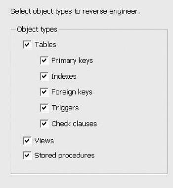
Figure 14-4: Selection of Object Types to Reverse Engineer.
Select Base Tables and or Views to Reverse Engineer
The next screen prompts you to select which base tables and/or views to reverse engineer. (Figure 14-5). Base tables are marked "T" and views are marked "V." In our example, there are four base tables and no views. By default, none are selected. If only some are needed, select the individual items by clicking the appropriate check box. If all are desired, then click Select All . To reset the selections, click Deselect All .
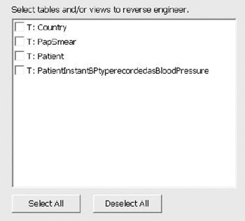
Figure 14-5: Choosing tables to reverse engineer.
A similar screen is displayed for selecting stored procedures (Figure 14-5). Note that no naming choices were used in the ORM model from which this database model was generated, so one of the stored procedures has a really long name . See Section 7.4 for ways to improve the names of logical model elements that are generated from an ORM model.
Place Shapes on the Drawing Window
The next screen allows you to choose whether to have shapes for the reverse engineered elements placed automatically on the drawing page (Figure 14-7). In general, if you have only a few tables, then select Yes. If you have many tables, it may be easier to arrange the layout manually. You can also use pagination when you lay it out manually, as discussed in section 12.8. Select your option, and click Next.
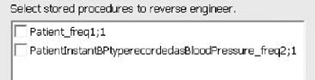
Figure 14-6: Choosing which stored procedures to reverse engineer.
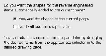
Figure 14-7: Layout Options.
Preview the Selection
The next screen provides a preview of the tables and catalog information to be reverse engineered (Figure 14-8). If the selections are correct, then click Finish otherwise click Back to change your selections, and then finish.
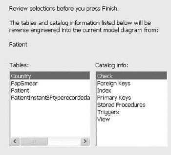
Figure 14-8: Reviewing the Selections for Reverse Engineering.
Reviewing the Result
The results of the reverse engineering are displayed in the output window (Figure 14-9). Make sure to review the contents for errors and warnings. If you encounter errors or serious warnings, you should correct these in the physical database prior to redoing the reverse engineering. Alternatively, you may deselect the object types creating the errors, and run the wizard again.
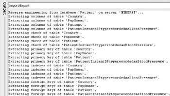
Figure 14-9: Beginning of Output Results of the Reverse Engineering.
If the reverse engineering succeeds, and you choose Yes for the automatic layout option, the model will now be laid out for you in the drawing window. Figure 14-10 shows the result for our worked example.
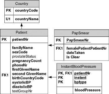
Figure 14-10: Logical Model Layout.
If you answered No, you may manually drag the relevant shapes from the Tables and Views window onto the drawing surface. If you drag one table onto the drawing window you can automatically add its related tables by right clicking on the table and selecting Show Related Tables from its context menu. Using this option gives you pagination control. You can create subject area pages, and place selected tables on each page.
If needed, you may now edit the logical model in the normal way to make any desired changes.
For our example, in addition to the tables shown on the diagram, stored procedures and check clauses were reverse engineered from the physical model. The code window contains two code types: Global Code and Local Code. Global Code includes stored procedures [SP] or code that is in a self-contained code block. The Local Code is contained in some other model element, in this case a table. The Code window is opened by the reverse engineering wizard (Figure 14-11).
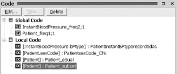
Figure 14-11: Code window.
Examples of the stored procedure code are displayed in Figures 14-12 and 14-13.
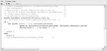
Figure 14-12: Procedure to enforce patient group frequency constraint.
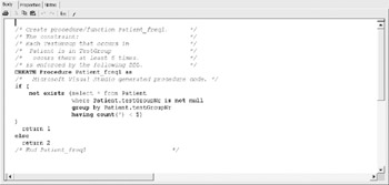
Figure 14-13: Procedure to enforce instant blood pressure frequency constraint.
The following check clause code was also reversed engineered.
Reverse Engineered Check Clauses


InstantBloodPressure.bPtype : PatientInstantBPTyperecordedas
 ([bPtype] = 'D' or [bPtype] = 'S')


PatientsexCode : PatientsexCode_Chk
 ([sexCode] = 'F' or [sexCode] = 'M')


Reversed Engineer Equality Constraint


Patient : Patient_equal
 ([diastolicBP] is null and [systolicBP] is null or [diastolicBP] is
 not null and [systolicBP] is not null)


Reversed Engineered Subset Constraint


Patient : Patient_subset
 ([firstGivenName] is not null or [secondGivenName] is null)
Handling Errors and Warnings
The reverse engineering process may encounter errors and fail to create the logical model. Each error is shown in the output window. Each error must be resolved in the physical model. In some situations, you may have to eliminate an object type instance from your selection list. If you choose to correct the physical database, it is a good idea to get a schema (DDL script) from your current database, and then create an empty version of the database. Make the corrections in this new version. Usually you do not have the luxury to change the production database. If you create a new empty database to solve these problems, you will need to establish a new ODBC connection or modify an existing one.
Other Reverse Engineering Options
You can also import ERwin models and older VisioModeler ORM models or logical models using the Import/Export option. To do this, choose Database > Import/Export from the main menu, and then select the desired option. For further details on this functionality, see Section 8.4.
Overview of Database Modeling and the Database Modeling Tool
The Conceptual Modeling Solution (ORM)
- Object Types, Predicates, and Basic Constraints
- ORM Constraints
- Configuring, Manipulating, and Reusing ORM Models
- Mapping ORM Models to Logical Database Models
- Reverse Engineering and Importing to ORM
- Conceptual Model Reports
The Logical Modeling Solution (ER and Relational)
- Creating a Basic Logical Database Model
- Generating a Physical Database Schema
- Editing Logical Models”Intermediate Aspects
- Editing Logical Models”Advanced Aspects
- Reverse Engineering Physical Schemas to Logical Models
- Logical Database Model Reports
Managing Database Projects
EAN: 2147483647
Pages: 150
