Configuring L2TPv3 Static Tunnels
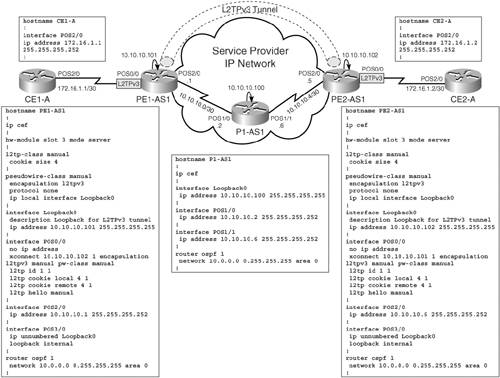
In this section, you will be provided with the configuration procedure for manual or static L2TPv3 tunnels in the network topology shown in Figure 10-6. Figure 10-6 shows an SP network with two PE routers, PE1-AS1 and PE2-AS1, connected to Customer A Routers CE1-A and CE2-A, respectively. The devices used in the test setup are GSR 12000 series routers for the provider cloud devices (PE1-AS1, PE2-AS1, and P1-AS1) and 7200 series routers for the CE devices. The GSRs were chosen for the provider cloud devices to depict tunnel server card configuration that does not apply to other platforms that support L2TPv3 functionality (7200s, 7500s, and 10700 routers).
Figure 10-6. L2TPv3 – Static Tunnels Topology and Base Configuration
For the GSR 12000 series routers functioning as PE1-AS1 and PE2-AS1 in the network topology, Slot 3 contains an OC48 POS line card that functions as the tunnel server card for the L2TPv3 tunnel. Therefore, all configurations pertaining to implementing a line card on a Cisco 12000 series router as the tunnel server card will be performed with perspective to Slot 3 on Routers PE1-AS1 and PE2-AS1. The following steps outline the configuration process to implement the L2TPv3 tunnel. The basic configuration for all devices in the setup prior to L2TPv3 tunnel configuration is also shown in Figure 10-6. The L2TPv3 specific configuration is illustrated in the following steps:
|
Step 1. |
Configure the L2TP class on each PE router. The L2TP class implements a template for control channel parameters that can be applied to different pseudowire classes on the router. For simplicity, the L2TP class is configured with a name "manual" and cookie size of 4 bytes, as shown in Example 10-1. Example 10-1. Configuration of L2TP Class Parameters PE1-AS1(config)#l2tp-class manual PE1-AS1(config-l2tp-class)# cookie size 4 ________________________________________________________________ PE2-AS1(config)#l2tp-class manual PE2-AS1(config-l2tp-class)#cookie size 4 |
|
Step 2. |
Configure the pseudowire class to define the session level parameters of the L2TPv3 sessions. For simplicity, the only configurations performed under the pseudowire class are the configurations of the encapsulation protocol (l2tpv3) and the local interface that will be used as the source of the tunnel. In addition, because static endpoints will be configured with the L2TPv3 tunnel, disable the use of any IP protocol for signaling (the default being the use of L2TPv3 for dynamic session establishment), as shown in Example 10-2. Example 10-2. Pseudowire Class Configuration PE1-AS1(config)#pseudowire-class manual PE1-AS1(config-pw-class)# encapsulation l2tpv3 PE1-AS1 (config-pw-class)# protocol none PE1-AS1 (config-pw-class)# ip local interface Loopback0 ________________________________________________________________ PE2-AS1(config)#pseudowire-class manual PE2-AS1(config-pw-class)# encapsulation l2tpv3 PE2-AS1 (config-pw-class)# protocol none PE2-AS1 (config-pw-class)# ip local interface Loopback0 |
|
Step 3. |
The next step is to associate the interface that will be a part of the tunnel with the parameters of the pseudowire. In addition, configurations need to be performed for the local and remote session IDs and the cookie values. In the configurations, a VC ID of 1 with a local session, remote session value of 1, and the cookie values of 1 are used. The configuration is shown in Example 10-3. Example 10-3. Attachment Circuit Configuration PE1-AS1(config)#interface pos 0/0 PE1-AS1(config-if)#xconnect 10.10.10.102 1 encapsulation l2tpv3 manual pw-class manual PE1-AS1(config-if-xconn)# l2tp id 1 1 PE1-AS1(config-if-xconn)# l2tp cookie local 4 1 PE1-AS1(config-if-xconn)# l2tp cookie remote 4 1 ________________________________________________________________ PE2-AS1(config)#interface pos 0/0 PE2-AS1(config-if)#xconnect 10.10.10.101 1 encapsulation l2tpv3 manual pw-class manual PE2-AS1(config-if-xconn)#l2tp id 1 1 PE2-AS1(config-if-xconn)#l2tp cookie local 4 1 PE2-AS1(config-if-xconn)# l2tp cookie remote 4 1 |
|
Step 4. |
This step applies only to Cisco GSR 12000 series routers. Configure the appropriate line card and slot on the GSR 12000 series router as the tunnel server card for processing L2TPv3 tunneled packets on the chassis. In our network, the configuration is performed on Routers PE1-AS1 and PE2-AS1 where the L2TPv3 tunnels are originated and terminated. This is shown in Example 10-4. Example 10-4. Tunnel Server Card Configuration PE1-AS1(config)#interface POS3/0 PE1-AS1(config-if)# ip unnumbered Loopback0 PE1-AS1(config-if)# loopback internal PE1-AS1(config)#hw-module slot 3 mode server ________________________________________________________________ PE2-AS1(config)#interface POS3/0 PE2-AS1(config-if)# ip unnumbered Loopback0 PE2-AS1(config-if)# loopback internal PE2-AS1(config)#hw-module slot 3 mode server |
Verification of Static L2TPv3 Tunnel Operation
The following verification steps are performed on the PE routers to validate L2TPv3 tunnel and Layer 2 VPN operation:
|
Step 1. |
Verify if the state of the tunnel is established, as shown in Example 10-5 in the output of the show l2tun tunnel all and show l2tun session all commands. Example 10-5. L2TPv3 Tunnel State Verification PE1-AS1#show l2tun tunnel all Tunnel Information Total tunnels 1 sessions 1 Tunnel id 31529 is up, remote id is 56005, 0 active sessions Tunnel state is established, time since change 00:30:56 Tunnel transport is IP (115) Remote tunnel name is PE2 Internet Address 10.10.10.102, port 0 Local tunnel name is PE1 Internet Address 10.10.10.101, port 0 Tunnel domain is VPDN group for tunnel is - L2TP class for tunnel is manual 0 packets sent, 0 received 0 bytes sent, 0 received Control Ns 31, Nr 31 Local RWS 8192 (default), Remote RWS 8192 (max) Tunnel PMTU checking disabled Retransmission time 1, max 1 seconds Unsent queuesize 0, max 0 Resend queuesize 0, max 1 Total resends 0, ZLB ACKs sent 30 Current nosession queue check 0 of 5 Retransmit time distribution: 0 0 0 0 0 0 0 0 0 Sessions disconnected due to lack of resources 0 PE1-AS1#show l2tun session all Session Information Total tunnels 1 sessions 1 Session id 1 is up, tunnel id 31529 Call serial number is 0 Remote tunnel name is PE2-AS1 Internet address is 10.10.10.102 Session is manually signalled Session state is established, time since change 00:24:21 197 Packets sent, 173 received 18252 Bytes sent, 11252 received Receive packets dropped: out-of-order: 0 total: 0 Send packets dropped: exceeded session MTU: 0 total: 0 Session vcid is 1 Session Layer 2 circuit, type is HDLC, name is POS0/0 Circuit state is UP Remote session id is 1, remote tunnel id 56005 DF bit off, ToS reflect disabled, ToS value 0, TTL value 255 Session cookie information: local cookie, size 4 bytes, value 00 00 00 01 remote cookie, size 4 bytes, value 00 00 00 01 SSS switching enabled Sequencing is off |
|
Step 2. |
Perform a ping from one CE router interface to the other CE router interface across the L2VPN tunnel. If all configurations have been performed correctly, connectivity is established between the CE routers and the customer sites, as shown in Example 10-6. Example 10-6. Verify IP Connectivity Between CE Routers CE1-A#ping 172.16.1.2 Type escape sequence to abort. Sending 5, 100-byte ICMP Echos to 172.16.1.2, timeout is 2 seconds: !!!!! Success rate is 100 percent (5/5), round-trip min/avg/max = 1/1/4 ms |
Final Device Configuration for L2TPv3 Static Tunnels
Figure 10-7 depicts the final configuration for devices to implement L2TPv3 static tunnels.
Figure 10-7. L2TPv3 Static Tunnels – Final Configuration
MPLS Overview
- MPLS Overview
- Unicast IP Forwarding in Traditional IP Networks
- Overview of MPLS Forwarding
- MPLS Terminology
- MPLS Control and Data Plane Components
- MPLS Operation
- Special Outgoing Label Types
- Penultimate Hop Popping
- Frame-Mode MPLS
- Cell-Mode MPLS
Basic MPLS Configuration
- Basic MPLS Configuration
- Frame-Mode MPLS Configuration and Verification
- Cell-Mode MPLS over ATM Overview, Configuration, and Verification
- Command Reference
Basic MPLS VPN Overview and Configuration
- Basic MPLS VPN Overview and Configuration
- VPN Categories
- MPLS VPN Architecture and Terminology
- MPLS VPN Routing Model
- MPLS VPN Basic Configuration
- Outbound Route Filters
- Command Reference
PE-CE Routing Protocol-Static and RIP
- PE-CE Routing Protocol-Static and RIP
- Static PE-CE Routing Overview, Configuration, and Verification
- Static PE-CE Routing Command Reference
- RIPv2 PE-CE Routing Overview, Configuration, and Verification
- RIPv1 PE-CE Routing Configuration and Verification
- RIP PE-CE Routing Command Reference
PE-CE Routing Protocol-OSPF and EIGRP
- PE-CE Routing Protocol-OSPF and EIGRP
- OSPF PE-CE Routing Protocol Overview, Configuration and Verification
- EIGRP PE-CE Routing Protocol Overview, Configuration, and Verification
Implementing BGP in MPLS VPNs
- Implementing BGP in MPLS VPNs
- BGP PE-CE Routing Protocol Overview, Configuration, and Verification
- Implementing Route-Reflectors in MPLS VPN Networks
- Case Study-Hub and Spoke MPLS VPN Network Using BGP PE-CE Routing for Sites Using Unique AS Numbers
- Case Study-Hub and Spoke MPLS VPN Network with Sites Using Same AS Numbers
- Command Reference
Inter-Provider VPNs
- Inter-Provider VPNs
- Overview of Inter-Provider VPNs
- Option 1: Inter-Provider VPN Using Back-to-Back VRF Method
- Option 2: Inter-Provider VPNs Using ASBR-to-ASBR Approach
- Option 3: Multi-Hop MP-eBGP Between RR and eBGP Between ASBRs
- Option 4: Non-VPN Transit Provider
- Case Study-Inter-AS Implementing Route-Reflector and BGP Confederation in Provider Networks
- Case Study-Multi-Homed Inter-AS Provider Network
- Command Reference
Carrier Supporting Carriers
- Carrier Supporting Carriers
- Carrier Supporting Carriers Overview
- Deployment Scenarios with CSC Architecture
- CSC Architecture Benefits
- Command Reference
MPLS Traffic Engineering
- MPLS Traffic Engineering
- TE Basics
- MPLS TE Theory
- Constraint-Based Routing and Operation in MPLS TE
- Configuring MPLS TE
- Command Reference
Implementing VPNs with Layer 2 Tunneling Protocol Version 3
- Implementing VPNs with Layer 2 Tunneling Protocol Version 3
- L2TPv3 Overview
- Configuring L2TPv3 Tunnels for Layer 2 VPN
- Configuring L2TPv3 Static Tunnels
- Configuring L2TPv3 Dynamic Tunnels
- Implementing Layer 3 VPNs over L2TPv3 Tunnels
- Command Reference
Any Transport over MPLS (AToM)
- Any Transport over MPLS (AToM)
- Introduction to Layer 2 VPNs
- Implementing AToM for Like to Like Circuits
- L2 VPN-Any to Any Interworking
- Local Switching
- Command Reference
Virtual Private LAN Service (VPLS)
- Virtual Private LAN Service (VPLS)
- VPLS Overview
- VPLS Topology-Single PE or Direct Attachment
- Hierarchical VPLS-Distributed PE Architecture
- Command Reference
Implementing Quality of Service in MPLS Networks
- Implementing Quality of Service in MPLS Networks
- Introduction to QoS-Classification and Marking
- MPLS QoS Implementation
- MPLS QoS Operating Modes
- Modular QoS CLI: Configuration of QoS on Cisco Routers
- Configuration and Implementation of MPLS QoS in Uniform Mode and Short Pipe Mode Operation
- Implementing MPLS QoS for Layer 2 VPN Implementations
- Command Reference
MPLS Features and Case Studies
- MPLS Features and Case Studies
- Case Study 1: Implementing Multicast Support for MPLS VPNs
- Case Study 2: Implementing Multi-VRF CE, VRF Selection Using Source IP Address, VRF Selection Using Policy-Based Routing, NAT and HSRP Support in MPLS VPN, and Multicast VPN Support over Multi-VRF CE
- Case Study 3: Implementing Layer 2 VPNs over Inter-AS Topologies Using Layer 2 VPN Pseudo-Wire Switching
- Case Study 4: Implementing Layer 3 VPNs over Layer 2 VPN Topologies and Providing L2 VPN Redundancy
- Case Study 5: Implementing Dynamic Layer 3 VPNs Using mGRE Tunnels
- Case Study 6: Implementing Class-Based Tunnel Selection with MPLS Traffic Engineering
- Case Study 7: Implementing Hub and Spoke Topologies with OSPF
- Case Study 8: Implementing Hub and Spoke Topologies with EIGRP
- Case Study 9: Implementing VPLS Services with the GSR 12000 Series
- Case Study 10: BGP Site of Origin
- Command Reference
EAN: 2147483647
Pages: 130
