Case Study 4: Implementing Layer 3 VPNs over Layer 2 VPN Topologies and Providing L2 VPN Redundancy
Case Study 4 Implementing Layer 3 VPNs over Layer 2 VPN Topologies and Providing L2 VPN Redundancy
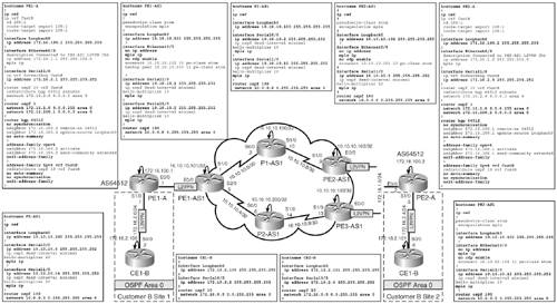
Figure 14-27 illustrates the topology used for this case study. The requirements posed by Customer A to the SP are as follows:
- Customer A requires Layer 2 VPN connectivity between Routers PE1-A and PE2-A via the SP backbone.
- Customer A requires the ability to provide other Layer 3 services using the connectivity provided by the SP. This includes the ability to provide Layer 3 VPN connectivity between two sites belonging to Customer B by implementing MPLS VPN over the Layer 2 VPN service provided by the SP.
- Customer A requires redundancy between Routers PE1-A and PE2-A connected via the SP infrastructure at Layer 2, enabling fast recovery during primary path failure between PE1-A and PE2-A using L2 VPN redundancy.
Figure 14-27. Case Study 4 Topology
Layer 3 VPN over L2 VPN Configuration
Figure 14-28 outlines the basic configurations for devices to implement Layer 3 VPNs for Customer B traffic (by Customer A), as well as implementation of Layer 2 AToM tunnels between PE1-A and PE2-A over the SP infrastructure.
Figure 14-28. Case Study 4: Layer 3 VPN for Customer B over Customer A Layer 2 VPN Configuration
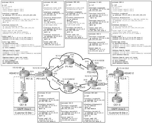
The highlighted portions in Figure 14-28 outline the pertinent configurations for the implementation of the following:
- L2 VPN Ethernet AToM configuration on PE1-AS1 and PE2-AS1 for L2 VPN connectivity between PE1-A and PE2-A
- Configurations on the Customer A PE Routers PE1-A and PE2-A to implement Layer 3 VPN using OSPF PE to CE for Customer B Sites 1 and 2 between Routers CE1-B and CE2-B
Implementing L2 VPN Redundancy
Customer A's final requirement is the ability to provide Layer 2 VPN redundancy between Sites PE1-A and PE2-A. To enable Layer 2 VPN redundancy, a third PE Router PE3-AS1 is connected to the same segment as between PE2-AS1 and PE2-A to provide Layer 2 VPN redundancy in the event of the primary VC failure between PE1-AS1 and PE2-AS1.
In the event of failure, all traffic from Customer A Site PE1-A must failover to the redundant path via PE3-AS1 to reach PE2-A. This is accomplished by configuration of a backup tunnel VC between PE1-AS1 and PE3-AS1 to the primary pseudo wire between PE1-AS1 and PE2-AS1.
Therefore, Layer 2 VPN redundancy when configured provides protection for the following failures:
- Failure of PE2-AS1 router
- Failure of link between P1-AS1 and PE2-AS1 routers
- Failure of link between PE2-AS1 and PE2-A
Layer 2 VPN Pseudo-Wire Redundancy enables you to configure a backup pseudo wire in case the primary pseudo wire fails. When the primary pseudo wire fails, the PE router can switch to the backup pseudo wire. Traffic can be switched back to the primary pseudo wire after the path is operational again.
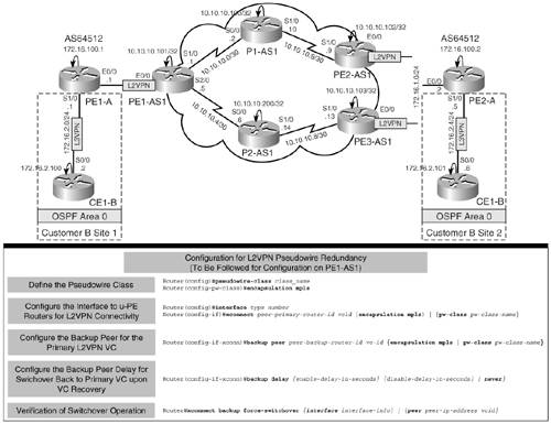
Configuration of Layer 2 VPN pseudo-wire redundancy and verification of its operation are performed using the procedure illustrated in Figure 14-29.
Figure 14-29. Layer 2 VPN Pseudo-Wire Redundancy Configuration Flowchart
Layer 2 VPN Pseudo-Wire Redundancy Configuration for Customer A Traffic from PE1-A to PE2-A
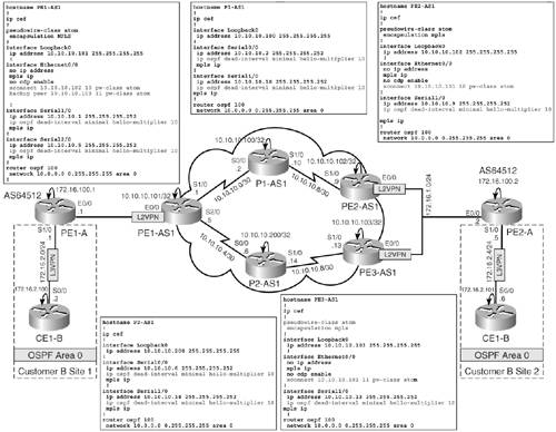
Layer 2 VPN pseudo-wire redundancy for Customer A traffic originating from PE1-A to PE2-A is configured by the association of a backup VC between PE1-AS1 and PE3-AS1 for the primary tunnel between PE1-AS1 and PE2-AS1. The configuration of the PE routers to implement L2 VPN pseudo-wire redundancy is shown in Figure 14-30. In addition, for quicker IGP convergence OSPF, fast hellos are configured on the SP router interfaces for immediate failover to redundant paths. Configurations of all other devices remain the same as shown earlier.
Figure 14-30. Case Study 4: L2 VPN Pseudo-Wire Redundancy Configuration
Verifications for Case Study 4
Figure 14-31 outlines the verifications performed on the various devices for Case Study 4. Verification operation of Layer 2 VPN circuits on PE1-AS1 and PE2-AS1 are done by performing show mpls l2transport vc on the routers, as shown in the figure. The output of PE1-AS1 must depict the primary Layer 2 VPN circuit as UP and the backup circuit as DOWN.
Figure 14-31. Case Study 4: Verifications

In addition, verification of Layer 3 VPN over Layer 2 VPN is performed as shown in Figure 14-31 by issuing show ip bgp vpnv4 all on the u-PE Routers PE1-A and PE2-A.
Finally, verify operation of the Layer 2 VPN pseudo-wire redundancy by performing an extended ping between the CE1-B and CE2-B loopback address and simultaneously performing xconnect backup force-switchover peer 10.10.10.103 11 on the PE1-AS1 router to force traffic between PE1-A and PE2-A to switch over to the backup pseudo wire, as illustrated in Figure 14-31. The outputs depict the loss of a single ping packet when pinging between CE2-B and CE1-B when the switchover is performed. The output also depicts the active pseudo wire after switchover.
Final Configurations for Case Study 4
Final configurations for devices in Case Study 4 are shown in Figure 14-32.
Figure 14-32. Case Study 4: Final Configurations
MPLS Overview
- MPLS Overview
- Unicast IP Forwarding in Traditional IP Networks
- Overview of MPLS Forwarding
- MPLS Terminology
- MPLS Control and Data Plane Components
- MPLS Operation
- Special Outgoing Label Types
- Penultimate Hop Popping
- Frame-Mode MPLS
- Cell-Mode MPLS
Basic MPLS Configuration
- Basic MPLS Configuration
- Frame-Mode MPLS Configuration and Verification
- Cell-Mode MPLS over ATM Overview, Configuration, and Verification
- Command Reference
Basic MPLS VPN Overview and Configuration
- Basic MPLS VPN Overview and Configuration
- VPN Categories
- MPLS VPN Architecture and Terminology
- MPLS VPN Routing Model
- MPLS VPN Basic Configuration
- Outbound Route Filters
- Command Reference
PE-CE Routing Protocol-Static and RIP
- PE-CE Routing Protocol-Static and RIP
- Static PE-CE Routing Overview, Configuration, and Verification
- Static PE-CE Routing Command Reference
- RIPv2 PE-CE Routing Overview, Configuration, and Verification
- RIPv1 PE-CE Routing Configuration and Verification
- RIP PE-CE Routing Command Reference
PE-CE Routing Protocol-OSPF and EIGRP
- PE-CE Routing Protocol-OSPF and EIGRP
- OSPF PE-CE Routing Protocol Overview, Configuration and Verification
- EIGRP PE-CE Routing Protocol Overview, Configuration, and Verification
Implementing BGP in MPLS VPNs
- Implementing BGP in MPLS VPNs
- BGP PE-CE Routing Protocol Overview, Configuration, and Verification
- Implementing Route-Reflectors in MPLS VPN Networks
- Case Study-Hub and Spoke MPLS VPN Network Using BGP PE-CE Routing for Sites Using Unique AS Numbers
- Case Study-Hub and Spoke MPLS VPN Network with Sites Using Same AS Numbers
- Command Reference
Inter-Provider VPNs
- Inter-Provider VPNs
- Overview of Inter-Provider VPNs
- Option 1: Inter-Provider VPN Using Back-to-Back VRF Method
- Option 2: Inter-Provider VPNs Using ASBR-to-ASBR Approach
- Option 3: Multi-Hop MP-eBGP Between RR and eBGP Between ASBRs
- Option 4: Non-VPN Transit Provider
- Case Study-Inter-AS Implementing Route-Reflector and BGP Confederation in Provider Networks
- Case Study-Multi-Homed Inter-AS Provider Network
- Command Reference
Carrier Supporting Carriers
- Carrier Supporting Carriers
- Carrier Supporting Carriers Overview
- Deployment Scenarios with CSC Architecture
- CSC Architecture Benefits
- Command Reference
MPLS Traffic Engineering
- MPLS Traffic Engineering
- TE Basics
- MPLS TE Theory
- Constraint-Based Routing and Operation in MPLS TE
- Configuring MPLS TE
- Command Reference
Implementing VPNs with Layer 2 Tunneling Protocol Version 3
- Implementing VPNs with Layer 2 Tunneling Protocol Version 3
- L2TPv3 Overview
- Configuring L2TPv3 Tunnels for Layer 2 VPN
- Configuring L2TPv3 Static Tunnels
- Configuring L2TPv3 Dynamic Tunnels
- Implementing Layer 3 VPNs over L2TPv3 Tunnels
- Command Reference
Any Transport over MPLS (AToM)
- Any Transport over MPLS (AToM)
- Introduction to Layer 2 VPNs
- Implementing AToM for Like to Like Circuits
- L2 VPN-Any to Any Interworking
- Local Switching
- Command Reference
Virtual Private LAN Service (VPLS)
- Virtual Private LAN Service (VPLS)
- VPLS Overview
- VPLS Topology-Single PE or Direct Attachment
- Hierarchical VPLS-Distributed PE Architecture
- Command Reference
Implementing Quality of Service in MPLS Networks
- Implementing Quality of Service in MPLS Networks
- Introduction to QoS-Classification and Marking
- MPLS QoS Implementation
- MPLS QoS Operating Modes
- Modular QoS CLI: Configuration of QoS on Cisco Routers
- Configuration and Implementation of MPLS QoS in Uniform Mode and Short Pipe Mode Operation
- Implementing MPLS QoS for Layer 2 VPN Implementations
- Command Reference
MPLS Features and Case Studies
- MPLS Features and Case Studies
- Case Study 1: Implementing Multicast Support for MPLS VPNs
- Case Study 2: Implementing Multi-VRF CE, VRF Selection Using Source IP Address, VRF Selection Using Policy-Based Routing, NAT and HSRP Support in MPLS VPN, and Multicast VPN Support over Multi-VRF CE
- Case Study 3: Implementing Layer 2 VPNs over Inter-AS Topologies Using Layer 2 VPN Pseudo-Wire Switching
- Case Study 4: Implementing Layer 3 VPNs over Layer 2 VPN Topologies and Providing L2 VPN Redundancy
- Case Study 5: Implementing Dynamic Layer 3 VPNs Using mGRE Tunnels
- Case Study 6: Implementing Class-Based Tunnel Selection with MPLS Traffic Engineering
- Case Study 7: Implementing Hub and Spoke Topologies with OSPF
- Case Study 8: Implementing Hub and Spoke Topologies with EIGRP
- Case Study 9: Implementing VPLS Services with the GSR 12000 Series
- Case Study 10: BGP Site of Origin
- Command Reference
EAN: 2147483647
Pages: 130
