Implementing Route-Reflectors in MPLS VPN Networks
BGP route-reflectors (RRs) are considered a scalability tool that allows network designers to steer away from BGP full mesh requirements. Classical iBGP split horizon rules mandate that updates received on eBGP sessions should be forwarded on all iBGP and eBGP sessions, but updates received on an iBGP session should be forwarded only on all eBGP sessions. This requires the BGP edge or boundary router (ASBR) to send updates to all other BGP-enabled routers in its own AS directly through individual iBGP sessions to each BGP router. RRs modify the iBGP split horizon rule and allow a specific router, under certain conditions, to forward all incoming iBGP updates to an outgoing iBGP session. This router is called a route-reflector.
Figure 6-5 shows a typical MPLS VPN-based network where, in the absence of RRs, whenever a new PE is introduced, each existing PE in the service provider network will require an additional BGP neighbor command associating it to the new PE. In BGP, updates received by a peer in an AS are not allowed to be forwarded to another peer within the same AS. Therefore, a BGP network must be fully meshed, with all peers adjacent to one another, as far as BGP routing updates are concerned. If the number of PEs becomes substantial enough to make this operation impractical (that is, adding neighbor commands in every PE), BGP RRs are recommended. RRs obviate the need to fully mesh the BGP peers and avoid the addition of neighbor commands to each PE. With RRs, the PEs would only require neighbors defined for each RR. Any updates, including VRF information, would be sent to the RR alone. The RRs are then responsible for propagating information received from PEs to all other PEs. Each time a new Edge LSR or PE is added, a neighbor statement pointing to the RR needs to be added on the new PE router, and on the RR, a neighbor statement pointing to the PE must be added.
Figure 6-5. RRs
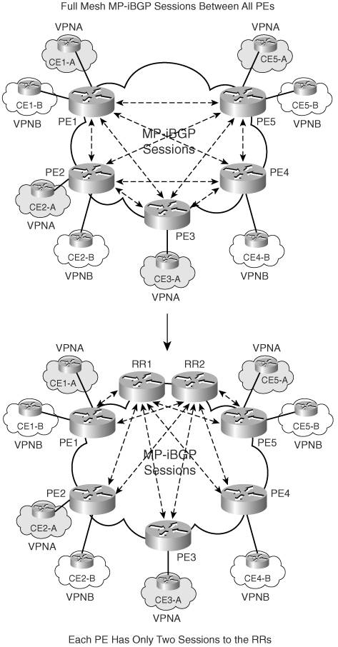
RRs are also useful in the event of a route change in the customer network. Without RRs, the PE that locally terminates that portion of the customer network would have to update every PE peer participating in that VPN. RRs, therefore, help remove the burden of BGP updates from the PE.
RR Deployment Methods
In MPLS-based VPN networks, RRs can be deployed in several ways.
Option 1 – Using PE Router as VPNv4 RR
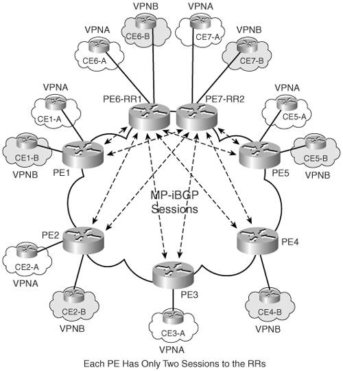
In this option, the PE device is used as a RR. This type of setup is not recommended due to additional constraints of memory and CPU imposed on the PE router, which is handling both the functions of providing services to client edge routers as well as reflecting routes to several other PEs in the same MPLS domain. Figure 6-6 provides an illustration of PE routers, PE6-RR1 and PE7-RR2, which are being used as VPNv4 RRs.
Figure 6-6. PE Routers as RRs
Option 2 – Using P Router as IPv4 and VPNv4 RR
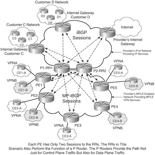
In this scenario, the provider (P) router is used both as an IPv4 and VPNv4 RR. The P router, in this case, handles not only the function of route reflection for IPv4 and VPNv4 routes, but also performs data forwarding operations for IPv4 traffic and VPNv4 traffic. Figure 6-7 shows a scenario in which the P routers, P1-RR1 and P2-RR2, are IPv4 RRs for the ISP's IPv4 network, which provides Internet services for Customer C and D. At the same time, those RRs serve as IPv4 and VPNv4 RR for the MPLS-enabled network, routing VPNv4 prefixes for VPNA and VPNB sites, as well as providing Internet services to those VPN sites. This scenario may not scale well in large MPLS VPN environments due to memory and CPU constraints imposed on the RR that not only provides IPv4 and VPNv4 routing services but also data forwarding functionality.
Figure 6-7. P Routers as IPv4 and VPNv4 RRs
Option 3 – Using P Router as RR Only for VPNv4
In this scenario, the P router is used only as a VPNv4 RR. The P router will forward both control and data plane forwarding for VPN sites only.
Figure 6-8 shows the scenario in which RRs P1-RR1 and P2-RR2 are used for reflecting only VPNv4 routes and forwarding all data traffic between VPN client sites. This implementation can be used in large-scale MPLS VPN environments in which the provider network wants to isolate IPv4 functionality on the VPNv4 RR; however, this can increase the provider's cost to maintain a dedicated RR for IPv4 routing and a dedicated RR for VPNv4 routes.
Figure 6-8. P Router Reflecting Only VPNv4 Routes

Option 4 – Dedicated Router as RR for IPv4 and VPNv4
In this scenario, an additional router performs the function of reflecting IPv4 and VPNv4 routes. The router does not perform any data forwarding functions.
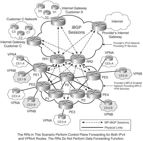
Figure 6-9 highlights the scenario in which P1-RR1 and P2-RR2 perform the function of reflecting VPNv4 and IPv4 routes and not that of data forwarding. This also increases the provider's operational costs because the provider has to dedicate routers as RRs for IPv4 and VPNv4 prefixes as well as ensure their PE routers have physical connectivity with each other for data forwarding functionality or are connected to a dedicated P router, which will perform data forwarding functionality.
Figure 6-9. Dedicated IPv4 and VPNv4 RR for Control Plane Functionality
Option 5 – Dedicated Router as RR for Only VPNv4
In this approach, the RR performs the task of reflecting only VPNv4 routes and not that of data forwarding. This approach also requires a dedicated router that can handle this functionality.
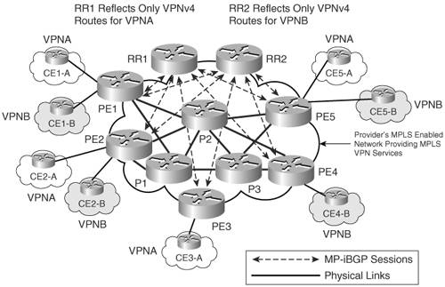
Figure 6-10 shows an MPLS environment adopting this approach. RR1 and RR2 reflect only VPNv4 routes and perform no data forwarding function. Using this approach, considerable savings in CPU and performance improvements can be realized but at the cost of additional routers providing provider router functionality and increased cost in providing physical connectivity between PE to P routers.
Figure 6-10. Dedicated VPNv4 RR for Control Plane Functionality

Option 6 – Partitioned RRs
This scenario is used primarily in large-scale environments in which using the dedicated VPNv4 RR does not scale to the demands of a large provider carrying a large number of VPNv4 prefixes.
In this approach, as shown in Figure 6-11, RR1 reflects VPNv4 routes only for VPNA, and RR2 reflects VPNv4 routes only for VPNB. There are no mandatory requirements that the RR in this approach should not perform the data forwarding function. However, the decision to forward data traffic or not should be made after evaluating future network growth. The drawback would be the additional cost of maintaining separate routers for performing P router functionality and the cost of connectivity between PE and P routers. The complexity of the network could increase with the use of partitioned RRs.
Figure 6-11. Route Partitioning Using RRs
Configuring P Router as RR Only for VPNv4 Prefixes (Option 3)
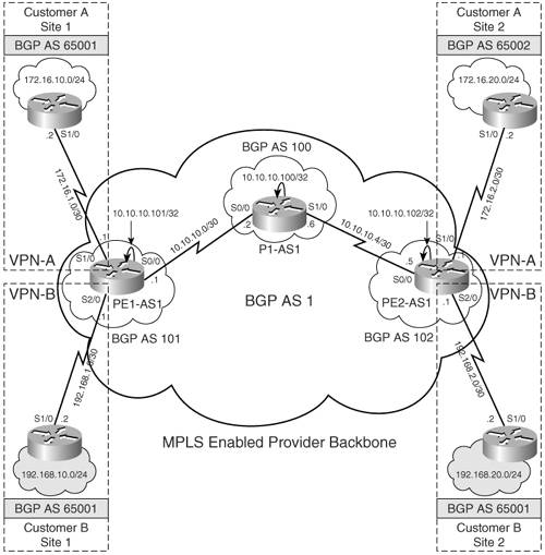
The objective of this configuration scenario is to demonstrate the RR configuration when the P router serves as an RR and performs both the control plane and data forwarding functionality for VPNv4 prefixes only (option 3). To implement this configuration, the network topology shown in Figure 6-1 is used except that P1-AS1-RR (for this configuration, the scenario hostname for P1-AS1 in Figure 6-1 is P1-AS1-RR) is configured as a RR peering with PE routers PE1-AS1 and PE2-AS1. PE routers will be configured to peer with the RRs only.
Configuration Flowchart for P Router as RR for Only VPNv4 Prefixes
The configuration flowchart for implementing this scenario is shown in Figure 6-12.
Figure 6-12. Configuration Flowchart to Implement RR
Configuration Step for PE Routers PE1-AS1 and PE2-AS1
To configure BGP peering on the PE routers PE1-AS1 and PE2-AS1 with the RR P1-AS1-RR, BGP routing on the PE routers must be configured and BGP neighbors activated. Enable global BGP routing on PE1-AS1 and PE2-AS1 routers and activate the BGP RR neighbors on the PE routers for VPNv4 route exchange only. Example 6-10 shows the configuration for defining P1-AS1-RR as the BGP neighbor on the PE router PE1-AS1. Use the same steps to configure PE2-AS1.
Example 6-10. Configure BGP Routing on PE Routers and Activate BGP Neighbors
PE1-AS1(config)#router bgp 1

PE1-AS1(config-router)#neighbor 10.10.10.100 remote-as 1

PE1-AS1(config-router)#neighbor 10.10.10.100 update-source Loopback0

PE1-AS1(config-router)#no bgp default ipv4-unicast

PE1-AS1(config-router)# address-family ipv4

PE1-AS1(config-router-af)#no neighbor 10.10.10.100 activate

PE1-AS1(config-router-af)#address-family vpnv4

PE1-AS1(config-router-af)#neighbor 10.10.10.100 activate

PE1-AS1(config-router-af)#neighbor 10.10.10.100 send-community extended

PE1-AS1(config-router-af)#exit-address-family
Configuration Step for P Router as RR for Only VPNv4 Prefixes
To configure the RR P1-AS1-RR, configure the P router as VPNv4 RR. Enable global BGP routing on the P router, P1-AS1-RR. Example 6-11 shows the configuration procedure to enable global BGP routing, define the BGP relationship with PE routers PE1-AS1 and PE2-AS1, activate them for VPNv4 route-exchange, and configure the PE routers as clients for the route-reflection process.
Example 6-11. Configure Provider Router as VPNv4 RR
P1-AS1-RR(config)#router bgp 1

P1-AS1-RR(config-router)#neighbor 10.10.10.101 remote-as 1

P1-AS1-RR(config-router)#neighbor 10.10.10.101 update-source Loopback0

P1-AS1-RR(config-router)#neighbor 10.10.10.102 remote-as 1

P1-AS1-RR(config-router)#neighbor 10.10.10.102 update-source Loopback0

P1-AS1-RR(config-router)#no bgp default ipv4-unicast

P1-AS1-RR(config-router)#address-family ipv4

P1-AS1-RR(config-router-af)#no neighbor 10.10.10.101 activate

P1-AS1-RR(config-router-af)#no neighbor 10.10.10.102 activate

P1-AS1-RR(config-router-af)#exit

P1-AS1-RR(config-router)#address-family vpnv4

P1-AS1-RR(config-router-af)#neighbor 10.10.10.102 route-reflector-client

P1-AS1-RR(config-router-af)#neighbor 10.10.10.102 route-reflector-client

P1-AS1-RR(config-router-af)#neighbor 10.10.10.101 activate

P1-AS1-RR(config-router-af)#neighbor 10.10.10.102 activate
CE Configurations
Refer to Example 6-4 for CE configurations.
P1-AS1-RR, PE1-AS1, and PE2-AS1 Final Configuration for MPLS VPN Using RRs
Example 6-12 outlines the final relevant configurations for PE1-AS1, PE2-AS1, and P1-AS1-RR implementing MPLS VPN for sites using the P router as a VPNv4 RR. Refer to Example 6-5 for the remaining configurations pertaining to each router.
Example 6-12. Relevant Configurations
hostname PE1-AS1

!

!For the remainder configuration refer to example 6-5

!

router bgp 1

 no bgp default ipv4-unicast

 bgp log-neighbor-changes

 neighbor 10.10.10.100 remote-as 1

 neighbor 10.10.10.100 update-source Loopback0

 !

 address-family vpnv4

 neighbor 10.10.10.100 activate

 neighbor 10.10.10.100 send-community extended

 exit-address-family

__________________________________________________________________________

hostname PE2-AS1

!

!For the remainder configuration refer to example 6-5

!

router bgp 1

 no bgp default ipv4-unicast

 bgp log-neighbor-changes

 neighbor 10.10.10.100 remote-as 1

 neighbor 10.10.10.100 update-source Loopback0

 !

 address-family vpnv4

 neighbor 10.10.10.100 activate

 neighbor 10.10.10.100 send-community extended

 exit-address-family

__________________________________________________________________________

hostname P1-AS1-RR

!

!For the remainder configuration refer to example 6-5

!

router bgp 1

 no bgp default ipv4-unicast

 bgp log-neighbor-changes

 neighbor 10.10.10.101 remote-as 1

 neighbor 10.10.10.101 update-source Loopback0

 neighbor 10.10.10.102 remote-as 1

 neighbor 10.10.10.102 update-source Loopback0

 !

 address-family vpnv4

 neighbor 10.10.10.101 activate

 neighbor 10.10.10.101 send-community extended

 neighbor 10.10.10.101 route-reflector-client

 neighbor 10.10.10.102 activate

 neighbor 10.10.10.102 send-community extended

 neighbor 10.10.10.102 route-reflector-client

 exit-address-family
Verifying MPLS VPNs Using RRs
The steps to verify MPLS VPNs using RRs are
|
Step 1. |
Verify BGP neighbor relationship on PE1-AS1 and PE2-AS1 – Verify the BGP neighbor relationship. Example 6-13 shows PE1-AS1 and PE2-AS1 have a BGP relationship with the CE routers for VRF VRF-BGP and have received prefixes from those peers. Example 6-13. Verify BGP Neighbor Relationship P1-AS1-RR#show ip bgp vpnv4 all summary Neighbor V AS MsgRcvd MsgSent TblVer InQ OutQ Up/Down State/PfxRcd 10.10.10.101 4 1 26 26 9 0 0 00:03:10 2 10.10.10.102 4 1 17 19 9 0 0 00:03:20 2 |
|
Step 2. |
Verify BGP VPNv4 routing table on P1-AS1-RR and PE1-AS1 – Check the BGP VPNv4 routing table to see if the routes are received as expected. Example 6-14 shows that P1-AS1-RR and PE1-AS1 receive the routes as expected. Example 6-14. Verify BGP VPNv4 Routing Table on P1-AS1-RR and PE1-AS1 P1-AS1-RR#show ip bgp vpnv4 all BGP table version is 9, local router ID is 10.10.10.100 Status codes: s suppressed, d damped, h history, * valid, > best, i - internal, r RIB-failure, S Stale Origin codes: i - IGP, e - EGP, ? - incomplete Network Next Hop Metric LocPrf Weight Path Route Distinguisher: 1:100 *>i172.16.10.0/24 10.10.10.101 0 100 0 65001 i *>i172.16.20.0/24 10.10.10.102 0 100 0 65002 i Route Distinguisher: 1:200 *>i192.168.10.0 10.10.10.101 0 100 0 65001 i *>i192.168.20.0 10.10.10.102 0 100 0 65001 i _______________________________________________________________________________ PE1-AS1#show ip bgp vpnv4 all BGP table version is 15, local router ID is 10.10.10.101 Status codes: s suppressed, d damped, h history, * valid, > best, i - internal, r RIB-failure, S Stale Origin codes: i - IGP, e - EGP, ? - incomplete Network Next Hop Metric LocPrf Weight Path Route Distinguisher: 1:100 (default for vrf Cust_A) *> 172.16.10.0/24 172.16.1.2 0 0 65001 i *>i172.16.20.0/24 10.10.10.102 0 100 0 65002 i Route Distinguisher: 1:200 (default for vrf Cust_B) *> 192.168.10.0 192.168.1.2 0 0 65001 i *>i192.168.20.0 10.10.10.102 0 100 0 65001 i |
|
Step 3. |
Verify end-to-end connectivity via ping – Verify end-to-end connectivity between the Customer A sites as well as Customer B sites. Example 6-15 shows the result of the ping. Example 6-15. Verify End-to-End Connectivity via Ping CE1-A#ping 172.16.20.1 source 172.16.10.1 Type escape sequence to abort. Sending 5, 100-byte ICMP Echos to 172.16.20.1, timeout is 2 seconds: Packet sent with a source address of 172.16.10.1 !!!!! Success rate is 100 percent (5/5), round-trip min/avg/max = 80/80/84 ms ________________________________________________________________________ CE1-B#ping 192.168.20.1 source 192.168.10.1 Type escape sequence to abort. Sending 5, 100-byte ICMP Echos to 192.168.20.1, timeout is 2 seconds: Packet sent with a source address of 192.168.10.1 !!!!! Success rate is 100 percent (5/5), round-trip min/avg/max = 80/80/80 ms |
Partitioned RRs
Existing RRs carrying VPNv4 routes will not scale to meet the demands of continually expanding MPLS VPN networks. Large MPLS VPN providers might have to resort to partitioning or segregating VPNv4 prefixes based on route targets or any other BGP attributes, for example, standard BGP communities, to accommodate a large number of VPNv4 routes.
Figure 6-13 shows a basic MPLS VPN network in which P1-RR accepts only VPN-A VPNv4 prefixes with a route-target value of 1:100, and P2-RR accepts only VPN-B VPNv4 prefixes with a route-target value of 1:200.
Figure 6-13. Route Partitioning
In order to receive all the routing information required for proper operation, all PE routers may need to have BGP sessions with all RRs. Further resource optimization can be achieved if the PE routers peer only with the relevant RRs. This deployment, although optimal, may lead to the providers incurring additional management and configuration complexity. Partitioning of RRs can be achieved by configuring
- Outbound or inbound filters – Outbound filters on the PE routers or inbound filters on RRs. In both cases, the filtering can be performed with a route-map, matching routes on any BGP attribute that is usually on route target or standard BGP community. Outbound filters (ORF) on the PE routers reduce bandwidth utilization and CPU utilization of the RRs. The disadvantage with outbound filters is that the service providers may incur additional operational burden due to constant maintenance required for these filters on all PE routers. On the other hand, inbound filters on RRs are optimal from a maintenance perspective, but may increase the CPU utilization of the RRs.
- BGP RR groups – Configure the inbound route-target filter on the BGP RR by using the bgp rr-group command. This command performs the same function as a route-map. However, it is configured under the BGP routing process and applies to all BGP neighbors. Also, another important operational detail is that the extended community access-list maintained on the RR is downloaded as an outbound filter to the PE routers through the ORF functionality. The route-map based input filter cannot be downloaded via ORF functionality.
As an alternate solution, the VPNv4 routing information can also be partitioned based on standard BGP communities. In the first design, outbound updates on the PE routers are filtered. Because the PE routers have to attach standard BGP community to the VPNv4 routes, the filtering of outbound VPNv4 routing updates based on the standard BGP community does not represent an additional maintenance burden.
The second design is to attach standard BGP communities to the VPNv4 routes on the PE routers and perform the filtering on the RRs, either in the inbound or outbound direction. This design achieves a clear separation of the marking of customer routes from the partitioning of VPNv4 routing information. Inbound filtering is preferred, because it reduces the volume of VPNv4 routing information on RRs.
RR Partitioning Using BGP Inbound Route-Target Filters
Figure 6-14 is similar to Figure 6-1 except that a second RR (P2-AS1-RR2) has been added to the topology. P1-AS1-RR1 and P2-AS1-RR2 perform both control and data plane functionality for VPNA and VPNB sites. As previously demonstrated, the configured route targets on PE1-AS1 and PE2-AS1 for VPNA and VPNB are 1:100 and 1:200, respectively. To demonstrate route partitioning, P1-AS1-RR1 will accept routes only for VPN-A (Cust_A) and P2-AS1-RR2 will accept routes only for VPN-B (Cust_B).
Figure 6-14. MPLS Network Implementing Route Partitioning Using Inbound Route-Target Filters
Figure 6-15 shows the flowchart to configure route partitioning using inbound route-target filters on RRs.
Figure 6-15. Configuration Steps for Partitioning Routes Using Inbound Route-Target Filters
Route-Partitioning Configuration Steps on the P Routers P1-RR and P2-RR
The configurations steps for the RRs are the same as those demonstrated in the section "Configuring P Router as RR Only for VPNv4 Prefixes (Option 3)." In addition to those steps, the following steps are required to configure route partitioning on the RRs:
|
Step 1. |
Create an extended-community access-list – The first step is to create an extended-community access-list on the RR that permits routes with the appropriate route-target value. P1-AS1-RR1 accepts only VPNv4 routes with the route target 1:100, and P2-AS1-RR2 accepts only VPNv4 prefixes with a route-target value of 1:200. Example 6-16 illustrates the configuration steps for creating an extended-community access-list. Example 6-16. Create an Extended-Community Access-List P1-AS1-RR1(config)#ip extcommunity-list standard VPNA P1-AS1-RR1(config-extcomm-list)#permit rt 1:100 ________________________________________________________________ P2-AS1-RR2(config)#ip extcommunity-list standard VPNB P2-AS1-RR2(config-extcomm-list)#permit rt 1:200 |
|
Step 2. |
Define the route-target based inbound filter – In this step, you configure the bgp rr-group command under the BGP routing process on the RRs. The extended-community list number should match that of the access-list configured in Step 1. Example 6-17 illustrates the steps to define the route-target based inbound filter on P1-AS1-RR1 and P2-AS1-RR2. Example 6-17. Define the Route-Target Based Inbound Filter P1-AS1-RR1(config)#router bgp 1 P1-AS1-RR1(config-router)#address-family vpnv4 P1-AS1-RR1(config-router-af)#bgp rr-group VPNA ________________________________________________________________ P2-AS1-RR2(config)#router bgp 1 P2-AS1-RR2(config-router)#address-family vpnv4 P2-AS1-RR2(config-router-af)#bgp rr-group VPNB |
PE1-AS1, PE2-AS1, P1-AS1-RR1, and P2-AS1-RR2 Final Configuration for Partitioned RRs
Example 6-18 shows only the additional configurations on PE1-AS1, PE2-AS1, and P1-AS1-RR1. The complete configuration is shown for P2-AS1-RR2. For the remaining configurations, refer to Example 6-5.
Example 6-18. PE1-AS1, PE2-AS1, P1-AS1-RR1, and P2-AS1-RR2 Final Configurations for Partitioned RRs
hostname PE1-AS1

!

!Refer to example 6-5 for the rest of the configuration

router bgp 1

neighbor 10.10.10.103 remote-as 1

neighbor 10.10.10.103 update-source Loopback0

 !

address-family vpnv4

neighbor 10.10.10.103 activate

neighbor 10.10.10.103 send-community extended

exit-address-family

__________________________________________________________________________

hostname PE2-AS1

!

!Refer to example 6-5 for the rest of the configuration

router bgp 1

neighbor 10.10.10.103 remote-as 1

neighbor 10.10.10.103 update-source Loopback0

 !

address-family vpnv4

neighbor 10.10.10.103 activate

neighbor 10.10.10.103 send-community extended

exit-address-family

__________________________________________________________________________

hostname P1-AS1-RR1

!

!Refer to example 6-5

!

router bgp 1

 no bgp default ipv4-unicast

 neighbor 10.10.10.101 remote-as 1

 neighbor 10.10.10.101 update-source Loopback0

 neighbor 10.10.10.102 remote-as 1

 neighbor 10.10.10.102 update-source Loopback0

 neighbor 10.10.10.103 remote-as 1

 neighbor 10.10.10.103 update-source Loopback0

 !

 address-family vpnv4

 neighbor 10.10.10.101 activate

 neighbor 10.10.10.101 send-community extended

 neighbor 10.10.10.101 route-reflector-client

 neighbor 10.10.10.102 activate

 neighbor 10.10.10.102 send-community extended

 neighbor 10.10.10.102 route-reflector-client

 neighbor 10.10.10.103 activate

 neighbor 10.10.10.103 send-community extended

 neighbor 10.10.10.103 route-reflector-client

 bgp rr-group VPNA

 exit-address-family

!

ip extcommunity-list standard VPNA permit rt 1:100

__________________________________________________________________________

hostname P2-AS1-RR2

!

mpls ldp router-id Loopback0

!

interface Loopback0

 ip address 10.10.10.103 255.255.255.255

!

interface Serial0/0

 ip address 10.10.10.10 255.255.255.252

 mpls ip

!

interface Serial1/0

 ip address 10.10.10.14 255.255.255.252

 mpls ip

!

interface Serial2/0

 ip address 10.10.10.18 255.255.255.252

 mpls ip

!

router ospf 1

 log-adjacency-changes

 network 10.0.0.0 0.255.255.255 area 0

!

router bgp 1

 no bgp default ipv4-unicast

 neighbor 10.10.10.101 remote-as 1

 neighbor 10.10.10.101 update-source Loopback0

 neighbor 10.10.10.102 remote-as 1

 neighbor 10.10.10.102 update-source Loopback0

 neighbor 10.10.10.100 remote-as 1

 neighbor 10.10.10.100 update-source Loopback0

 !

 address-family vpnv4

 neighbor 10.10.10.101 activate

 neighbor 10.10.10.101 send-community extended

 neighbor 10.10.10.101 route-reflector-client

 neighbor 10.10.10.102 activate

 neighbor 10.10.10.102 send-community extended

 neighbor 10.10.10.102 route-reflector-client

 neighbor 10.10.10.100 activate

 neighbor 10.10.10.100 send-community extended

 neighbor 10.10.10.100 route-reflector-client

 bgp rr-group VPNB

 exit-address-family

!

ip extcommunity-list standard VPNB permit rt 1:200
Verifying Partitioned RRs
The steps to verify partitioned RRs are
|
Step 1. |
Verify BGP VPNv4 routing table on P1-AS1-RR1 and P2-AS1-RR2 – Verify the BGP VPNv4 routing table on P1-AS1-RR1 and P2-AS1-RR2. Example 6-19 shows that P1-AS1-RR1 shows VPNv4 routes for VPNA and P2-AS1-RR2 sees VPNv4 routes for VPNB. Example 6-19. Verify BGP VPNv4 Routing Table on P1-AS1-RR1 and P2-AS1-RR2 P1-AS1-RR1# show ip bgp vpnv4 all BGP table version is 3, local router ID is 10.10.10.100 Status codes: s suppressed, d damped, h history, * valid, > best, i - internal, r RIB-failure, S Stale Origin codes: i - IGP, e - EGP, ? - incomplete Network Next Hop Metric LocPrf Weight Path Route Distinguisher: 1:100 *>i172.16.10.0/24 10.10.10.101 0 100 0 65001 i *>i172.16.20.0/24 10.10.10.102 0 100 0 65002 i ______________________________________________________________________________ P2-AS1-RR2#show ip bgp vpnv4 all BGP table version is 23, local router ID is 10.10.10.103 Status codes: s suppressed, d damped, h history, * valid, > best, i - internal, r RIB-failure, S Stale Origin codes: i - IGP, e - EGP, ? - incomplete Network Next Hop Metric LocPrf Weight Path Route Distinguisher: 1:200 *>i192.168.10.0 10.10.10.101 0 100 0 65001 i *>i192.168.20.0 10.10.10.102 0 100 0 65001 i |
|
Step 2. |
Verify end-to-end connectivity via ping – Ping the edge customer networks from CE1-A to CE2-A and CE1-B to CE2-B. Example 6-20 shows the successful ping outputs. Example 6-20. Verify End-to-End Connectivity via Ping CE1-A#ping 172.16.20.1 source 172.16.10.1 Type escape sequence to abort. Sending 5, 100-byte ICMP Echos to 172.16.20.1, timeout is 2 seconds: Packet sent with a source address of 172.16.10.1 !!!!! Success rate is 100 percent (5/5), round-trip min/avg/max = 80/81/88 ms ________________________________________________________________________ CE1-B#ping 192.168.20.1 source 192.168.10.1 Type escape sequence to abort. Sending 5, 100-byte ICMP Echos to 192.168.20.1, timeout is 2 seconds: Packet sent with a source address of 192.168.10.1 !!!!! Success rate is 100 percent (5/5), round-trip min/avg/max = 80/82/88 ms |
RR Partitioning Using Standard BGP Communities
This configuration scenario demonstrates RR partitioning using standard BGP communities. The same topology as what's shown in Figure 6-14 is used for this scenario. The objective is to ensure that P1-AS1-RR1 will accept routes only for VPNA (Cust_A) and P2-AS1-RR2 will accept routes only for VPNB (Cust_B).
Figure 6-16 shows the steps to configure route partitioning using standard BGP communities.
Figure 6-16. Configuration Flowchart for Partitioning Routes Using Standard BGP Communities
Configuration Steps on the PE Routers PE1-AS1 and PE2-AS1
On the PE routers, set the community for the CE1-A and CE1-B prefixes on PE1-AS1 and for CE2-A and CE2-B on PE2-AS1. Example 6-21 shows the additional relevant configuration on PE1-AS1. Repeat the same steps on PE2-AS1.
Example 6-21. PE1-AS1 Configuration
PE1-AS1(config)#router bgp 1

PE1-AS1(config-router)#address-family vpnv4

PE1-AS1(config-router-af)#neighbor 10.10.10.100 send-community both

PE1-AS1(config-router-af)#neighbor 10.10.10.100 route-map allow1 out

PE1-AS1(config-router-af)#neighbor 10.10.10.103 send-community both

PE1-AS1(config-router-af)#neighbor 10.10.10.103 route-map allow2 out

PE1-AS1(config-router-af)#exit-address-family

PE1-AS1(config-router)#exit

PE1-AS1(config)#ip bgp-community new-format

PE1-AS1(config)#access-list 10 permit 172.16.10.0 0.0.0.255

PE1-AS1(config)#access-list 20 permit 192.168.10.0 0.0.0.255

PE1-AS1(config)#route-map allow2 permit 10

PE1-AS1(config-route-map)# match ip address 20

PE1-AS1(config-route-map)# set community 1:200

PE1-AS1(config-route-map)#exit

PE1-AS1(config)#route-map allow1 permit 10

PE1-AS1(config-route-map)# match ip address 10

PE1-AS1(config-route-map)# set community 1:100
Configuration Steps on the P Routers P1-AS1-RR1 and P2-AS1-RR2
The configuration steps for the RRs are the same as demonstrated in the section "Configuration Step for PE Routers PE1-AS1 and PE2-AS1." In addition to that step, the following steps are required to configure route partitioning on the RRs using standard BGP communities:
|
Step 1. |
Create a community access-list and route-map policy – Create a community access-list that permits the route with the route-target value that is to be accepted by the RR. P1-RR is accepting only VPNv4 with the route target 1:100, and P2-RR is accepting only VPNv4 prefixes with the route-target value of 1:200. Prior to this, make sure that the routers are configured with ip bgp-community new-format. Example 6-22 shows the relevant configuration on the RRs. Example 6-22. Create a Community Access-List and Route-Map Policy P1-AS1-RR1(config)#ip community-list 1 permit 1:100 P1-AS1-RR1(config)#route-map allow-VPNA permit 10 P1-AS1-RR1(config-route-map)#match community 1 ________________________________________________________________ P2-AS1-RR2(config)#ip community-list 1 permit 1:200 P2-AS1-RR2(config)#route-map allow-VPNB permit 10 P2-AS1-RR2(config-route-map)#match community 1 |
|
Step 2. |
Apply the route-map to the BGP PE neighbor – In this step, apply the route-map to the relevant BGP neighbors. This is shown in Example 6-23. Example 6-23. Apply the Route-Map to the BGP Neighbors P1-AS1-RR1(config)#router bgp 1 P1-AS1-RR1(config-router)#address-family vpnv4 P1-AS1-RR1(config-router-af)#neighbor 10.10.10.101 route-map allow-VPNA in P1-AS1-RR1(config-router-af)#neighbor 10.10.10.102 route-map allow-VPNA in P1-AS1-RR1(config-router-af)#neighbor 10.10.10.103 route-map allow-VPNA in ______________________________________________________________________________ P2-AS1-RR2(config)#router bgp 1 P2-AS1-RR2(config-router)#address-family vpnv4 P2-AS1-RR2(config-router-af)#neighbor 10.10.10.101 route-map allow-VPNB in P2-AS1-RR2(config-router-af)#neighbor 10.10.10.102 route-map allow-VPNB in P2-AS1-RR2(config-router-af)#neighbor 10.10.10.100 route-map allow-VPNB in |
PE1-AS1 and PE2-AS1 Final Configuration for Partitioned RRs
Example 6-24 shows the relevant configuration on the PE1-AS1, PE2-AS1, and P routers.
Example 6-24. Relevant Configuration on the PE1-AS1, PE2-AS1, and P Routers
!PE1-AS1 Router Configuration

router bgp 1

 no bgp default ipv4-unicast

 bgp log-neighbor-changes

 neighbor 10.10.10.100 remote-as 1

 neighbor 10.10.10.100 update-source Loopback0

 neighbor 10.10.10.103 remote-as 1

 neighbor 10.10.10.103 update-source Loopback0

 !

 address-family vpnv4

 neighbor 10.10.10.100 activate

 neighbor 10.10.10.100 send-community both

 neighbor 10.10.10.100 route-map allow1 out

 neighbor 10.10.10.103 activate

 neighbor 10.10.10.103 send-community both

 neighbor 10.10.10.103 route-map allow2 out

 exit-address-family

!

ip bgp-community new-format

!

access-list 10 permit 172.16.10.0 0.0.0.255

access-list 20 permit 192.168.10.0 0.0.0.255

!

route-map allow1 permit 10

 match ip address 10

 set community 1:100

!

route-map allow2 permit 10

 match ip address 20

 set community 1:200

________________________________________________________________

!PE2-AS1 Router Configuration

router bgp 1

 no bgp default ipv4-unicast

 bgp log-neighbor-changes

 neighbor 10.10.10.100 remote-as 1

 neighbor 10.10.10.100 update-source Loopback0

 neighbor 10.10.10.103 remote-as 1

 neighbor 10.10.10.103 update-source Loopback0

 !

 address-family vpnv4

 neighbor 10.10.10.100 activate

 neighbor 10.10.10.100 send-community both

 neighbor 10.10.10.100 route-map allow1 out

 neighbor 10.10.10.103 activate

 neighbor 10.10.10.103 send-community both

 neighbor 10.10.10.103 route-map allow2 out

 exit-address-family

!

ip bgp-community new-format

!

access-list 10 permit 172.16.20.0 0.0.0.255

access-list 20 permit 192.168.20.0 0.0.0.255

!

route-map allow1 permit 10

 match ip address 10

 set community 1:100

!

route-map allow2 permit 10

 match ip address 20

 set community 1:200

________________________________________________________________

!P1-RR Router Configuration

router bgp 1

 no bgp default ipv4-unicast

 bgp log-neighbor-changes

 neighbor 10.10.10.101 remote-as 1

 neighbor 10.10.10.101 update-source Loopback0

 neighbor 10.10.10.102 remote-as 1

 neighbor 10.10.10.102 update-source Loopback0

 neighbor 10.10.10.103 remote-as 1

 neighbor 10.10.10.103 update-source Loopback0

 !

 address-family vpnv4

 neighbor 10.10.10.101 activate

 neighbor 10.10.10.101 send-community both

 neighbor 10.10.10.101 route-reflector-client

 neighbor 10.10.10.101 route-map allow-VPNA in

 neighbor 10.10.10.102 activate

 neighbor 10.10.10.102 send-community both

 neighbor 10.10.10.102 route-reflector-client

 neighbor 10.10.10.102 route-map allow-VPNA in

 neighbor 10.10.10.103 activate

 neighbor 10.10.10.103 send-community both

 neighbor 10.10.10.103 route-map allow-VPNA in

 exit-address-family

!

ip bgp-community new-format

ip community-list 1 permit 1:100

!

route-map allow-VPNA permit 10

 match community 1

________________________________________________________________

!P2-RR Router Configuration

router bgp 1

 no bgp default ipv4-unicast

 bgp log-neighbor-changes

 neighbor 10.10.10.100 remote-as 1

 neighbor 10.10.10.100 update-source Loopback0

 neighbor 10.10.10.101 remote-as 1

 neighbor 10.10.10.101 update-source Loopback0

 neighbor 10.10.10.102 remote-as 1

 neighbor 10.10.10.102 update-source Loopback0

 !

 address-family vpnv4

 neighbor 10.10.10.100 activate

 neighbor 10.10.10.100 send-community both

 neighbor 10.10.10.100 route-map allow-VPNB in

 neighbor 10.10.10.101 activate

 neighbor 10.10.10.101 send-community both

 neighbor 10.10.10.101 route-reflector-client

 neighbor 10.10.10.101 route-map allow-VPNB in

 neighbor 10.10.10.102 activate

 neighbor 10.10.10.102 send-community both

 neighbor 10.10.10.102 route-reflector-client

 neighbor 10.10.10.102 route-map allow-VPNB in

 exit-address-family

!

ip bgp-community new-format

ip community-list 1 permit 1:200

!

route-map allow-VPNB permit 10

 match community 1
Verifying Partitioned RRs Using Standard BGP Communities
The steps to verify partitioned RRs using standard BGP communities are
|
Step 1. |
Verify BGP VPNv4 routing table on P1-RR and P2-RR – Example 6-25 shows the VPNv4 routing table on P1-AS1-RR1 and P2-AS1-RR2. Example 6-25. show ip bgp vpnv4 all on P1-AS1-RR1 and P2-AS1-RR2 P1-AS1-RR1# show ip bgp vpnv4 all BGP table version is 3, local router ID is 10.10.10.100 Status codes: s suppressed, d damped, h history, * valid, > best, i - internal, r RIB-failure, S Stale Origin codes: i - IGP, e - EGP, ? - incomplete Network Next Hop Metric LocPrf Weight Path Route Distinguisher: 1:100 *>i172.16.10.0/24 10.10.10.101 0 100 0 65001 i *>i172.16.20.0/24 10.10.10.102 0 100 0 65002 i _______________________________________________________________________________ P2-AS1-RR2#show ip bgp vpnv4 all BGP table version is 3, local router ID is 10.10.10.103 Status codes: s suppressed, d damped, h history, * valid, > best, i - internal, r RIB-failure, S Stale Origin codes: i - IGP, e - EGP, ? - incomplete Network Next Hop Metric LocPrf Weight Path Route Distinguisher: 1:200 *>i192.168.10.0 10.10.10.101 0 100 0 65001 i *>i192.168.20.0 10.10.10.102 0 100 0 65001 i |
|
Step 2. |
Verify connectivity via ping – Example 6-26 demonstrates this step. Example 6-26. Verify Connectivity via Ping CE1-A#ping 172.16.20.1 source 172.16.10.1 Type escape sequence to abort. Sending 5, 100-byte ICMP Echos to 172.16.20.1, timeout is 2 seconds: Packet sent with a source address of 172.16.10.1 !!!!! Success rate is 100 percent (5/5), round-trip min/avg/max = 80/80/84 ms __________________________________________________________________________ CE1-B#ping 192.168.20.1 source 192.168.10.1 Type escape sequence to abort. Sending 5, 100-byte ICMP Echos to 192.168.20.1, timeout is 2 seconds: Packet sent with a source address of 192.168.10.1 !!!!! Success rate is 100 percent (5/5), round-trip min/avg/max = 80/80/84 ms |
RRs and Peer Groups
A BGP peer group is a collection of BGP neighbors that share the same outbound policies. Instead of configuring each neighbor with the same policy individually, peer groups allow the user to group the policies that can be applied to individual peers. Using BGP peer groups reduces the amount of system resources (CPU and memory) used by allowing the routing table to be checked only once and updates to be replicated to all peer group members instead of being done individually for each peer in the peer group. The reduction in system resources, however, depends on the number of peer group members, the number of prefixes in the table, and the number of prefixes that are being advertised or being imported. The other benefit of peer groups is also to help in simplifying the BGP configuration.
Figure 6-17 shows an MPLS VPN network where P1-AS1-RR and P2-AS1-RR are RRs for PE1-AS1 and PE2-AS1 PE routers. PE1-AS1 and PE2-AS1 are both members of peer group group1 and group2 on P1-AS1-RR and P2-AS1-RR, respectively.
Figure 6-17. PE1-AS1 and PE2-AS1 Members of Peer Group group1 and group2
Figure 6-18 shows the steps to configure peer groups in a RR-based MPLS VPN network.
Figure 6-18. Configuration Steps for RRs with Peer Groups
Configuring Peer Groups on P Routers P1-AS1-RR1 and P2-AS1-RR2
The steps to configure peer groups on P routers P1-AS1-RR1 and P2-AS1-RR2 are
|
Step 1. |
Define the peer groups on P1-AS1-RR1 and P2-AS1-RR2 – The first step in configuring the peer groups is to define the peer group name on the P1-AS1-RR1 and P2-AS1-RR2 routers, as displayed in Example 6-27. Example 6-27. Define Peer Groups P1-AS1-RR1(config)#router bgp 1 P1-AS1-RR1(config-router)#neighbor group1 peer-group ________________________________________________________________ P2-AS1-RR2(config)#router bgp 1 P2-AS1-RR2(config-router)#neighbor group2 peer-group |
|
Step 2. |
Configure the remote AS for the peer group – In this step, the remote BGP AS is defined for the peer group. Example 6-28 shows the relevant steps. Example 6-28. Configure the Remote AS for the Peer Group P1-AS1-RR1(config-router)#neighbor group1 remote-as 1 ________________________________________________________________ P2-AS1-RR2(config-router)#neighbor group2 remote-as 1 |
|
Step 3. |
Associate the peer group with remote BGP PE neighbors – In this step, associate the peer group with the remote BGP PE neighbors in the VPNv4 address-family. This configuration step is shown in Example 6-29. Example 6-29. Associate the Peer Group with Remote BGP PE Neighbors P1-AS1-RR1(config-router)#address-family vpnv4 P1-AS1-RR1(config-router-af)#neighbor 10.10.10.101 peer-group group1 P1-AS1-RR1(config-router-af)#neighbor 10.10.10.102 peer-group group1 ______________________________________________________________________ P2-AS1-RR2(config-router)#address-family vpnv4 P2-AS1-RR2(config-router-af)#neighbor 10.10.10.101 peer-group group2 P2-AS1-RR2(config-router-af)#neighbor 10.10.10.102 peer-group group2 In this case, the router is configured to serve only as a VPNv4 RR to reflect VPNv4 prefixes and, as a result, configuring the neighbor peer-group command in the VPNv4 address-family would result in the Example 6-30 configuration to be inserted in the P1-AS1-RR1 and P2-AS1-RR2 configuration. Example 6-30. neighbor Peer Group Command address-family ipv4 neighbor group1 activate no neighbor 10.10.10.101 activate no neighbor 10.10.10.102 activate |
|
Step 4. |
Configure the routers to function as RRs – To enable the routers for RR functionality, you need to enter the VPNv4 address-family configuration mode and use the neighbor route-reflector-client command. Example 6-31 demonstrates this configuration step. Example 6-31. Configure the Routers to Function as RRs P1-AS1-RR1(config-router)#address-family vpnv4 P1-AS1-RR1(config-router-af)# neighbor group1 route-reflector-client _____________________________________________________________________ P2-AS1-RR2(config-router)#address-family vpnv4 P2-AS1-RR2(config-router-af)# neighbor group2 route-reflector-client Another key point to note is that the peer groups need not be activated under the VPNv4 address-family. They are automatically activated when peer-group parameters are defined. The message in Example 6-32 is shown if the peer group is activated under the VPNv4 address-family. Example 6-32. Message if the Peer Group Is Activated Under the VPNv4 Address-Family P1-AS1-RR12(config-router)#address-family vpnv4 P1-AS1-RR12(config-router-af)#neighbor group1 activate % Peergroups are automatically activated when parameters are configured |
P1-AS1-RR1 and P2-AS1-RR2 Final RR Configurations with Peer Groups
Example 6-33 shows the relevant configuration on P1-AS1-RR1 and P2-AS1-RR2.
Example 6-33. P1-AS1-RR1 and P2-AS1-RR2 Configuration
!P1-AS1-RR1 Router Configuration

router bgp 1

 no bgp default ipv4-unicast

 neighbor group1 peer-group

 neighbor group1 remote-as 1

 neighbor group1 update-source Loopback0

 neighbor 10.10.10.101 peer-group group1

 neighbor 10.10.10.102 peer-group group1

 neighbor 10.10.10.103 remote-as 1

 neighbor 10.10.10.103 update-source Loopback0

 !

 address-family vpnv4

 neighbor group1 send-community extended

 neighbor group1 route-reflector-client

 neighbor 10.10.10.101 activate

 neighbor 10.10.10.102 activate

 neighbor 10.10.10.103 activate

 neighbor 10.10.10.103 send-community extended

 exit-address-family

________________________________________________________________

!P2-AS1-RR2 Router Configuration

router bgp 1

 no bgp default ipv4-unicast

 neighbor group2 peer-group

 neighbor group2 remote-as 1

 neighbor group2 update-source Loopback0

 neighbor 10.10.10.100 remote-as 1

 neighbor 10.10.10.100 update-source Loopback0

 neighbor 10.10.10.101 peer-group group2

 neighbor 10.10.10.102 peer-group group2

 !

 address-family ipv4

 no auto-summary

 no synchronization

 exit-address-family

 !

 address-family vpnv4

 neighbor group2 send-community extended

 neighbor group2 route-reflector-client

 neighbor 10.10.10.100 activate

 neighbor 10.10.10.100 send-community extended

 neighbor 10.10.10.101 activate

 neighbor 10.10.10.102 activate

 exit-address-family
Verifying Peer Groups and RRs
The steps to verify peer groups and RRs are
|
Step 1. |
Verify peer group formation – Verify if PE1-AS1 and PE2-AS1 are part of the BGP peer groups group1 and group2. Example 6-34 shows that PE1-AS1 and PE2-AS1 are part of peer group group1 on P1-AS1-RR1 and part of group2 on P2-AS1-RR2. Example 6-34. Verify Peer Group Formation P1-AS1-RR1#show ip bgp peer-group group1 BGP peer-group is group1, remote AS 1 BGP version 4 Default minimum time between advertisement runs is 5 seconds For address family: VPNv4 Unicast BGP neighbor is group1, peer-group internal, members: 10.10.10.101 10.10.10.102 Index 0, Offset 0, Mask 0x0 Route-Reflector Client Update messages formatted 0, replicated 0 Number of NLRIs in the update sent: max 0, min 0 ________________________________________________________________ P2-AS1-RR2#show ip bgp peer-group group2 BGP peer-group is group2, remote AS 1 BGP version 4 Default minimum time between advertisement runs is 5 seconds For address family: VPNv4 Unicast BGP neighbor is group2, peer-group internal, members: 10.10.10.101 10.10.10.102 Index 0, Offset 0, Mask 0x0 Route-Reflector Client Update messages formatted 0, replicated 0 Number of NLRIs in the update sent: max 0, min 0 |
|
Step 2. |
Verify BGP VPNv4 routing table on P1-AS1-RR1 – Check the BGP VPNv4 routing table to see if routes are received as expected. Example 6-35 shows that P1-AS1-RR1 and PE1-AS1 receive the routes as expected. Example 6-35. Verify BGP VPNv4 Routing Table on P1-AS1-RR P1-AS1-RR1#show ip bgp vpnv4 all BGP table version is 5, local router ID is 10.10.10.100 Status codes: s suppressed, d damped, h history, * valid, > best, i - internal, r RIB-failure, S Stale Origin codes: i - IGP, e - EGP, ? - incomplete Network Next Hop Metric LocPrf Weight Path Route Distinguisher: 1:100 * i172.16.10.0/24 10.10.10.101 0 100 0 65001 i *>i 10.10.10.101 0 100 0 65001 i * i172.16.20.0/24 10.10.10.102 0 100 0 65002 i *>i 10.10.10.102 0 100 0 65002 i Route Distinguisher: 1:200 * i192.168.10.0 10.10.10.101 0 100 0 65001 i *>i 10.10.10.101 0 100 0 65001 i * i192.168.20.0 10.10.10.102 0 100 0 65001 i *>i 10.10.10.102 0 100 0 65001 i ________________________________________________________________________________ PE1-AS1#show ip bgp vpnv4 all BGP table version is 9, local router ID is 10.10.10.101 Status codes: s suppressed, d damped, h history, * valid, > best, i - internal, r RIB-failure, S Stale Origin codes: i - IGP, e - EGP, ? - incomplete Network Next Hop Metric LocPrf Weight Path Route Distinguisher: 1:100 (default for vrf Cust_A) *> 172.16.10.0/24 172.16.1.2 0 0 65001 i * i172.16.20.0/24 10.10.10.102 0 100 0 65002 i *>i 10.10.10.102 0 100 0 65002 i Route Distinguisher: 1:200 (default for vrf Cust_B) *> 192.168.10.0 192.168.1.2 0 0 65001 i * i192.168.20.0 10.10.10.102 0 100 0 65001 i *>i 10.10.10.102 0 100 0 65001 i |
|
Step 3. |
Verify end-to-end connectivity via ping – Verify end-to-end connectivity between the Customer A sites as well as Customer B sites. Example 6-36 shows the result of the ping. Example 6-36. Verify End-to-End Connectivity via Ping CE1-A#ping 172.16.20.1 source 172.16.10.1 Type escape sequence to abort. Sending 5, 100-byte ICMP Echos to 172.16.20.1, timeout is 2 seconds: Packet sent with a source address of 172.16.10.1 !!!!! Success rate is 100 percent (5/5), round-trip min/avg/max = 80/80/84 ms _______________________________________________________________________ CE1-B#ping 192.168.20.1 source 192.168.10.1 Type escape sequence to abort. Sending 5, 100-byte ICMP Echos to 192.168.20.1, timeout is 2 seconds: Packet sent with a source address of 192.168.10.1 !!!!! Success rate is 100 percent (5/5), round-trip min/avg/max = 80/80/80 ms |
BGP Confederations
BGP confederation is another BGP scalability tool that can reduce the iBGP mesh inside an AS. In BGP confederation, an AS is divided into multiple autonomous systems or sub autonomous systems, and these are assigned to a single confederation. Each sub AS will be fully iBGP meshed. Each sub AS will also have connections to other autonomous systems inside the confederation. Each sub AS will be eBGP peered with other sub autonomous systems. Although the sub autonomous systems will be eBGP peered to other autonomous systems within the confederation, they will exchange routing as if they were using iBGP; next hop, metric, and local preference information will be preserved. To the outside world, the confederation (the group of autonomous systems) will look like a single AS.
Figure 6-19 shows a provider network, AS 1, which is divided into multiple sub autonomous systems, AS 100, AS 101, and AS 102. Each sub AS is iBGP fully meshed, and there is eBGP peering between the sub autonomous systems. To BGP CE neighbors, the confederation (the group of autonomous systems, AS 100, 101, and 102) will look like a single BGP AS 1.
Figure 6-19. BGP Confederation
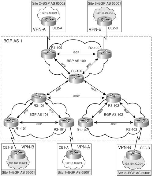
Figure 6-20 shows an MPLS VPN network in which BGP AS 1 is divided into three sub autonomous systems, AS 100, AS 101, and AS 102. P1-AS1, PE1-AS1, and PE2-AS1 are in AS 100, AS 101, and AS 102.
Figure 6-20. MPLS VPN Network Using BGP Confederations
Configuration Flowchart to Implement BGP Confederations
Figure 6-21 shows the configuration flowchart to implement BGP confederation in the provider core.
Figure 6-21. Configuration Flowchart to Implement BGP Confederations
Configuring BGP Confederation for P Routers PE1-AS1, PE2-AS1, and P1-AS1
The steps to configure BGP confederation for the topology shown in Figure 6-20 are as follows. The steps are shown for PE1-AS1 and PE2-AS1. Configure P1-AS1 similarly:
|
Step 1. |
Define BGP confederation identifier and peers – The first step is to configure the BGP confederation identifier and peers. Example 6-37 demonstrates the step. Example 6-37. Define BGP Confederation Identifier and Peers PE1-AS1(config)#router bgp 101 PE1-AS1(config-router)# bgp confederation identifier 1 PE1-AS1(config-router)# bgp confederation peers 100 102 ________________________________________________________________ PE2-AS1(config)#router bgp 102 PE2-AS1(config-router)# bgp confederation identifier 1 PE2-AS1(config-router)#bgp confederation peers 100 101 |
|
Step 2. |
Define BGP neighbors – In this step, the remote BGP AS for the peer group is defined. Example 6-38 shows the relevant steps. Example 6-38. Define BGP Neighbors PE1-AS1(config-router)# neighbor 10.10.10.102 remote-as 102 PE1-AS1(config-router)# neighbor 10.10.10.102 ebgp-multihop 2 PE1-AS1(config-router)# neighbor 10.10.10.102 update-source Loopback0 PE1-AS1(config-router)# neighbor 10.10.10.200 remote-as 100 PE1-AS1(config-router)# neighbor 10.10.10.200 ebgp-multihop 2 PE1-AS1(config-router)# neighbor 10.10.10.200 update-source Loopback0 _______________________________________________________________________ PE2-AS1(config-router)# neighbor 10.10.10.101 remote-as 101 PE2-AS1(config-router)# neighbor 10.10.10.101 ebgp-multihop 2 PE2-AS1(config-router)# neighbor 10.10.10.101 update-source Loopback0 PE2-AS1(config-router)# neighbor 10.10.10.200 remote-as 100 PE2-AS1(config-router)# neighbor 10.10.10.200 ebgp-multihop 2 PE2-AS1(config-router)# neighbor 10.10.10.200 update-source Loopback0 |
|
Step 3. |
Activate the BGP neighbors for VPNv4 exchange – In this step, activate the BGP neighbors to exchange VPNv4 prefixes. Example 6-39 demonstrates this configuration step. Example 6-39. Activate the BGP Neighbors for VPNv4 Exchange PE1-AS1(config-router)# address-family vpnv4 PE1-AS1(config-router-af)# neighbor 10.10.10.102 activate PE1-AS1(config-router-af)# neighbor 10.10.10.102 next-hop-self PE1-AS1(config-router-af)# neighbor 10.10.10.200 activate PE1-AS1(config-router-af)# neighbor 10.10.10.200 next-hop-self __________________________________________________________________ PE2-AS1(config-router)# address-family vpnv4 PE2-AS1(config-router-af)# neighbor 10.10.10.101 activate PE2-AS1(config-router-af)# neighbor 10.10.10.101 next-hop-self PE2-AS1(config-router-af)# neighbor 10.10.10.200 activate PE2-AS1(config-router-af)# neighbor 10.10.10.200 next-hop-self To ensure that the router sends and receives only VPNv4 prefixes, use the configuration shown in Example 6-40 in BGP router configuration mode. Example 6-40. Ensuring That the Router Sends and Receives Only VPNv4 Prefixes PE1-AS1(config)#router bgp 101 PE1-AS1(config-router)# no bgp default ipv4-unicast PE1-AS1(config-router)# no address-family ipv4 |
Final BGP Confederation Configuration on PE1-AS1, P1-AS1, and PE2-AS1
Example 6-41 shows the relevant configuration on PE1-AS1, P1-AS1, and PE2-AS1.
Example 6-41. PE1-AS1, P1-AS1, and PE2-AS1 Configuration
hostname PE1-AS1

!Refer to examples on VRF, interface, and OSPF configuration

!

router bgp 101

 no bgp default ipv4-unicast

 bgp log-neighbor-changes

 bgp confederation identifier 1

 bgp confederation peers 100 102

 neighbor 10.10.10.102 remote-as 102

 neighbor 10.10.10.102 ebgp-multihop 2

 neighbor 10.10.10.102 update-source Loopback0

 neighbor 10.10.10.200 remote-as 100

 neighbor 10.10.10.200 ebgp-multihop 2

 neighbor 10.10.10.200 update-source Loopback0

 !

 address-family vpnv4

 neighbor 10.10.10.102 activate

 neighbor 10.10.10.102 send-community extended

 neighbor 10.10.10.102 next-hop-self

 neighbor 10.10.10.200 activate

 neighbor 10.10.10.200 send-community extended

 neighbor 10.10.10.200 next-hop-self

 exit-address-family

 !

 address-family ipv4 vrf Cust_B

 neighbor 192.168.1.2 remote-as 65001

 neighbor 192.168.1.2 activate

 neighbor 192.168.1.2 as-override

 no auto-summary

 no synchronization

 exit-address-family

 !

 address-family ipv4 vrf Cust_A

 neighbor 172.16.1.2 remote-as 65001

 neighbor 172.16.1.2 activate

 no auto-summary

 no synchronization

 exit-address-family

__________________________________________________________________________

hostname P1-AS1

!Refer to examples on VRF, interface, and OSPF configuration>

!

router bgp 100

 no bgp default ipv4-unicast

 bgp log-neighbor-changes

 bgp confederation identifier 1

 bgp confederation peers 101 102

 neighbor 10.10.10.101 remote-as 101

 neighbor 10.10.10.101 ebgp-multihop 2

 neighbor 10.10.10.101 update-source Loopback0

 neighbor 10.10.10.102 remote-as 102

 neighbor 10.10.10.102 ebgp-multihop 2

 neighbor 10.10.10.102 update-source Loopback0

 !

 address-family vpnv4

 neighbor 10.10.10.101 activate

 neighbor 10.10.10.101 send-community extended

 neighbor 10.10.10.101 next-hop-self

 neighbor 10.10.10.102 activate

 neighbor 10.10.10.102 send-community extended

 neighbor 10.10.10.102 next-hop-self

 exit-address-family

__________________________________________________________________________

hostname PE2-AS1

!Refer to examples on VRF, interface, and OSPF configuration>

!

router bgp 102

 no bgp default ipv4-unicast

 bgp log-neighbor-changes

 bgp confederation identifier 1

 bgp confederation peers 100 101

 neighbor 10.10.10.101 remote-as 101

 neighbor 10.10.10.101 ebgp-multihop 2

 neighbor 10.10.10.101 update-source Loopback0

 neighbor 10.10.10.200 remote-as 100

 neighbor 10.10.10.200 ebgp-multihop 2

 neighbor 10.10.10.200 update-source Loopback0

 !

 address-family vpnv4

 neighbor 10.10.10.101 activate

 neighbor 10.10.10.101 send-community extended

 neighbor 10.10.10.101 next-hop-self

 neighbor 10.10.10.200 activate

 neighbor 10.10.10.200 send-community extended

 neighbor 10.10.10.200 next-hop-self

 exit-address-family

 !

 address-family ipv4 vrf Cust_B

 neighbor 192.168.2.2 remote-as 65001

 neighbor 192.168.2.2 activate

 neighbor 192.168.2.2 as-override

 no auto-summary

 no synchronization

exit-address-family

!

address-family ipv4 vrf Cust_A

neighbor 172.16.2.2 remote-as 65002

neighbor 172.16.2.2 activate

no auto-summary

no synchronization

exit-address-family
Verifying BGP Confederations
The steps to verify BGP confederations are
|
Step 1. |
Verify BGP neighbors – Example 6-42 shows that PE1-AS1 has established a BGP neighbor relationship with PE2-AS1 in AS 102 and P1-AS1 in AS 100. Example 6-42. Verify BGP Neighbor Between BGP Confederations PE1-AS1#show ip bgp vpnv4 all summary BGP router identifier 10.10.10.101, local AS number 101 BGP table version is 21, main routing table version 21 4 network entries using 532 bytes of memory 4 path entries using 272 bytes of memory 6/4 BGP path/bestpath attribute entries using 648 bytes of memory 3 BGP AS-PATH entries using 72 bytes of memory 2 BGP extended community entries using 48 bytes of memory 0 BGP route-map cache entries using 0 bytes of memory 0 BGP filter-list cache entries using 0 bytes of memory BGP using 1572 total bytes of memory BGP activity 4/0 prefixes, 8/4 paths, scan interval 15 secs Neighbor V AS MsgRcvd MsgSent TblVer InQ OutQ Up/Down State/PfxRcd 10.10.10.102 4 102 34 34 19 0 0 00:00:25 2 10.10.10.200 4 100 27 46 19 0 0 00:00:47 0 172.16.1.2 4 65001 22 25 17 0 0 00:17:04 1 192.168.1.2 4 65001 22 25 17 0 0 00:17:03 1 |
|
Step 2. |
Verify the BGP VPNv4 routing table on PE routers – Check the BGP VPNv4 routing table to see if routes are received as expected. Example 6-43 shows that PE1-AS1 and PE2-AS1 receive the routes as expected. Example 6-43. Verify BGP VPNv4 on PE Routers PE1-AS1#show ip bgp vpnv4 all BGP table version is 9, local router ID is 10.10.10.101 Status codes: s suppressed, d damped, h history, * valid, > best, i - internal, r RIB-failure, S Stale Origin codes: i - IGP, e - EGP, ? - incomplete Network Next Hop Metric LocPrf Weight Path Route Distinguisher: 1:100 (default for vrf Cust_A) *> 172.16.10.0/24 172.16.1.2 0 0 65001 i *> 172.16.20.0/24 10.10.10.102 0 100 0 (102) 65002 i Route Distinguisher: 1:200 (default for vrf Cust_B) *> 192.168.10.0 192.168.1.2 0 0 65001 i *> 192.168.20.0 10.10.10.102 0 100 0 (102) 65001 i _______________________________________________________________________________ PE2-AS1#show ip bgp vpnv4 all BGP table version is 9, local router ID is 10.10.10.102 Status codes: s suppressed, d damped, h history, * valid, > best, i - internal, r RIB-failure, S Stale Origin codes: i - IGP, e - EGP, ? - incomplete Network Next Hop Metric LocPrf Weight Path Route Distinguisher: 1:100 (default for vrf Cust_A) *> 172.16.10.0/24 10.10.10.101 0 100 0 (101) 65001 i *> 172.16.20.0/24 172.16.2.2 0 0 65002 i Route Distinguisher: 1:200 (default for vrf Cust_B) *> 192.168.10.0 10.10.10.101 0 100 0 (101) 65001 i *> 192.168.20.0 192.168.2.2 0 0 65001 i |
|
Step 3. |
Verify end-to-end connectivity via ping – Verify end-to-end connectivity between the Customer A sites and the Customer B sites. Example 6-44 shows the result of the ping. Example 6-44. Verify End-to-End Connectivity via Ping CE1-A#ping 172.16.20.1 source 172.16.10.1 Type escape sequence to abort. Sending 5, 100-byte ICMP Echos to 172.16.20.1, timeout is 2 seconds: Packet sent with a source address of 172.16.10.1 !!!!! Success rate is 100 percent (5/5), round-trip min/avg/max = 80/80/84 ms __________________________________________________________________________ CE1-B#ping 192.168.20.1 source 192.168.10.1 Type escape sequence to abort. Sending 5, 100-byte ICMP Echos to 192.168.20.1, timeout is 2 seconds: Packet sent with a source address of 192.168.10.1 !!!!! Success rate is 100 percent (5/5), round-trip min/avg/max = 80/80/80 ms |
MPLS Overview
- MPLS Overview
- Unicast IP Forwarding in Traditional IP Networks
- Overview of MPLS Forwarding
- MPLS Terminology
- MPLS Control and Data Plane Components
- MPLS Operation
- Special Outgoing Label Types
- Penultimate Hop Popping
- Frame-Mode MPLS
- Cell-Mode MPLS
Basic MPLS Configuration
- Basic MPLS Configuration
- Frame-Mode MPLS Configuration and Verification
- Cell-Mode MPLS over ATM Overview, Configuration, and Verification
- Command Reference
Basic MPLS VPN Overview and Configuration
- Basic MPLS VPN Overview and Configuration
- VPN Categories
- MPLS VPN Architecture and Terminology
- MPLS VPN Routing Model
- MPLS VPN Basic Configuration
- Outbound Route Filters
- Command Reference
PE-CE Routing Protocol-Static and RIP
- PE-CE Routing Protocol-Static and RIP
- Static PE-CE Routing Overview, Configuration, and Verification
- Static PE-CE Routing Command Reference
- RIPv2 PE-CE Routing Overview, Configuration, and Verification
- RIPv1 PE-CE Routing Configuration and Verification
- RIP PE-CE Routing Command Reference
PE-CE Routing Protocol-OSPF and EIGRP
- PE-CE Routing Protocol-OSPF and EIGRP
- OSPF PE-CE Routing Protocol Overview, Configuration and Verification
- EIGRP PE-CE Routing Protocol Overview, Configuration, and Verification
Implementing BGP in MPLS VPNs
- Implementing BGP in MPLS VPNs
- BGP PE-CE Routing Protocol Overview, Configuration, and Verification
- Implementing Route-Reflectors in MPLS VPN Networks
- Case Study-Hub and Spoke MPLS VPN Network Using BGP PE-CE Routing for Sites Using Unique AS Numbers
- Case Study-Hub and Spoke MPLS VPN Network with Sites Using Same AS Numbers
- Command Reference
Inter-Provider VPNs
- Inter-Provider VPNs
- Overview of Inter-Provider VPNs
- Option 1: Inter-Provider VPN Using Back-to-Back VRF Method
- Option 2: Inter-Provider VPNs Using ASBR-to-ASBR Approach
- Option 3: Multi-Hop MP-eBGP Between RR and eBGP Between ASBRs
- Option 4: Non-VPN Transit Provider
- Case Study-Inter-AS Implementing Route-Reflector and BGP Confederation in Provider Networks
- Case Study-Multi-Homed Inter-AS Provider Network
- Command Reference
Carrier Supporting Carriers
- Carrier Supporting Carriers
- Carrier Supporting Carriers Overview
- Deployment Scenarios with CSC Architecture
- CSC Architecture Benefits
- Command Reference
MPLS Traffic Engineering
- MPLS Traffic Engineering
- TE Basics
- MPLS TE Theory
- Constraint-Based Routing and Operation in MPLS TE
- Configuring MPLS TE
- Command Reference
Implementing VPNs with Layer 2 Tunneling Protocol Version 3
- Implementing VPNs with Layer 2 Tunneling Protocol Version 3
- L2TPv3 Overview
- Configuring L2TPv3 Tunnels for Layer 2 VPN
- Configuring L2TPv3 Static Tunnels
- Configuring L2TPv3 Dynamic Tunnels
- Implementing Layer 3 VPNs over L2TPv3 Tunnels
- Command Reference
Any Transport over MPLS (AToM)
- Any Transport over MPLS (AToM)
- Introduction to Layer 2 VPNs
- Implementing AToM for Like to Like Circuits
- L2 VPN-Any to Any Interworking
- Local Switching
- Command Reference
Virtual Private LAN Service (VPLS)
- Virtual Private LAN Service (VPLS)
- VPLS Overview
- VPLS Topology-Single PE or Direct Attachment
- Hierarchical VPLS-Distributed PE Architecture
- Command Reference
Implementing Quality of Service in MPLS Networks
- Implementing Quality of Service in MPLS Networks
- Introduction to QoS-Classification and Marking
- MPLS QoS Implementation
- MPLS QoS Operating Modes
- Modular QoS CLI: Configuration of QoS on Cisco Routers
- Configuration and Implementation of MPLS QoS in Uniform Mode and Short Pipe Mode Operation
- Implementing MPLS QoS for Layer 2 VPN Implementations
- Command Reference
MPLS Features and Case Studies
- MPLS Features and Case Studies
- Case Study 1: Implementing Multicast Support for MPLS VPNs
- Case Study 2: Implementing Multi-VRF CE, VRF Selection Using Source IP Address, VRF Selection Using Policy-Based Routing, NAT and HSRP Support in MPLS VPN, and Multicast VPN Support over Multi-VRF CE
- Case Study 3: Implementing Layer 2 VPNs over Inter-AS Topologies Using Layer 2 VPN Pseudo-Wire Switching
- Case Study 4: Implementing Layer 3 VPNs over Layer 2 VPN Topologies and Providing L2 VPN Redundancy
- Case Study 5: Implementing Dynamic Layer 3 VPNs Using mGRE Tunnels
- Case Study 6: Implementing Class-Based Tunnel Selection with MPLS Traffic Engineering
- Case Study 7: Implementing Hub and Spoke Topologies with OSPF
- Case Study 8: Implementing Hub and Spoke Topologies with EIGRP
- Case Study 9: Implementing VPLS Services with the GSR 12000 Series
- Case Study 10: BGP Site of Origin
- Command Reference
EAN: 2147483647
Pages: 130
