Option 3: Multi-Hop MP-eBGP Between RR and eBGP Between ASBRs
Option 3 Multi Hop MP eBGP Between RR and eBGP Between ASBRs
This approach is considered to be more scalable than option 1 or option 2. In this option, VPNv4 information is held by the RRs. To meet this requirement, each provider needs to have local RRs for VPNv4 prefix distribution and eBGP connection to exchange prefixes with the external peer. The ASBRs in this option participate in exchange of BGP next-hop-address using IPv4 labels, and RRs form an MP-eBGP session to transport VPNv4 information. Figure 7-25 shows a multiprovider VPN network that is providing VPN services to sites belonging to Customer A.
Figure 7-25. MPLS VPN Network Using Option 3
P1-AS1-RR and P1-AS2-RR are RRs that are local to each of the provider's autonomous systems. An MP-eBGP session is formed between the RRs to transport VPNv4 information across the multiprovider network. An eBGP session is formed between the ASBRs to exchange next-hop-address prefixes.
Control Plane Forwarding in Option 3
Figure 7-26 shows the control plane forwarding action that takes place for prefix 172.16.10.0/24 advertised by CE1-A to CE2-A that belongs to the same VPN, CUST_A.
Figure 7-26. Control Plane Operation in Option 3
Data Forwarding in Option 3
The source and destination networks are located on two different MPLS VPN provider networks. The data forwarding path originates from the source address of the flow, which is 172.16.20.1 destined to the 172.16.10.1. Figure 7-27 traces the path of the data packet from the source to the destination.
Figure 7-27. Data Forwarding in Option 3

Configuration Flowchart to Implement Option 3
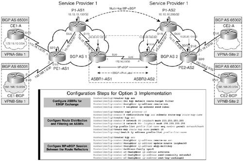
Figure 7-28 shows the configuration steps that are involved in accomplishing a functional Inter-AS network using option 3.
Figure 7-28. Configuration Steps for Option 3
Configuration and Verification of Option 3
The steps to implement option 3 for the topology shown in Figure 7-26 are as follows:
|
Step 1. |
Configure ASBRs for eBGP and IPv4 label exchange – Configure the ASBR Routers ASBR1-AS1 and ASBR2-AS2 for eBGP. Use the neighbor send-label command to enable exchange of IPv4 label exchange between the two peers. Example 7-18 demonstrates the step. Example 7-18. Configure ASBRs for eBGP and IPv4 Label Exchange ASBR1-AS1(config)#router bgp 1 ASBR1-AS1(config-router)#no bgp default route-target filter ASBR1-AS1(config-router)#neighbor 172.16.3.2 remote-as 2 ASBR1-AS1(config-router)# neighbor 172.16.3.2 send-label _____________________________________________________________________ ASBR2-AS2(config)#router bgp 2 ASBR2-AS2(config-router)#no bgp default route-target filter ASBR2-AS2(config-router)#neighbor 172.16.3.1 remote-as 1 ASBR2-AS2(config-router)# neighbor 172.16.3.1 send-label |
|
Step 2. |
Route redistribution and filtering on ASBR – In this step, the loopbacks on PE1-AS1 (10.10.10.101) and P1-AS1 (10.10.10.200) are advertised in BGP so that they can be advertised to ASBR2-AS2. At ASBR2-AS2, PE1-AS1 and P1-AS1-RR loopbacks are redistributed in IGP. Example 7-19 illustrates this step. Example 7-19. Route Redistribution and Filtering on ASBR ASBR1-AS1(config)#router ospf 1 ASBR1-AS1(config-router)# redistribute bgp 1 subnets route-map bgp-to-ospf ASBR1-AS1(config)#router bgp 1 ASBR1-AS1(config-router)# network 10.10.10.101 mask 255.255.255.255 ASBR1-AS1(config-router)# network 10.10.10.200 mask 255.255.255.255 ASBR1-AS1(config)#ip prefix-list pref-from-AS2 seq 1 permit 10.20.20.101/32 ASBR1-AS1(config)#ip prefix-list pref-from-AS2 seq 2 permit 10.20.20.200/32 ASBR1-AS1(config)#route-map bgp-to-ospf permit 10 ASBR1-AS1(config-rmap)#match ip address prefix-list pref-from-AS2 ___________________________________________________________________________ ASBR1-AS2(config)#router ospf 2 ASBR1-AS2(config-router)# redistribute bgp 2 subnets route-map bgp-to-ospf ASBR2-AS2(config)#router bgp 1 ASBR2-AS2(config-router)# network 10.20.20.101 mask 255.255.255.255 ASBR2-AS2(config-router)# network 10.20.20.200 mask 255.255.255.255 ASBR2-AS2(config)#ip prefix-list pref-from-AS1 seq 1 permit 10.10.10.101/32 ASBR2-AS2(config)#ip prefix-list pref-from-AS1 seq 2 permit 10.10.10.200/32 ASBR2-AS2(config)#route-map bgp-to-ospf permit 10 ASBR2-AS2(config-rmap)#match ip address prefix-list pref-from-AS1 |
|
Step 3. |
Configure MP-eBGP session between the RRs – In this step, an MP-eBGP session is configured between the RR, as shown in Example 7-20. Before performing this step, ensure that the loopback addresses on the RRs are reachable by ping. Example 7-20. Configure MP-eBGP Session Between the RRs P1-AS1-RR(config)#router bgp 1 P1-AS1-RR(config-router)#neighbor 10.20.20.200 remote-as 2 P1-AS1-RR(config-router)#neighbor 10.20.20.200 update-source loopback0 P1-AS1-RR(config-router)#neighbor 10.20.20.200 ebgp-multihop P1-AS1-RR(config-router)#address-family vpnv4 P1-AS1-RR(config-router-af)#neighbor 10.20.20.200 activate P1-AS1-RR(config-router-af)#neighbor 10.20.20.200 send-community extended _________________________________________________________________________ P1-AS1-RR(config-router-af)#neighbor 10.20.20.200 next-hop-unchanged P1-AS2-RR(config)#router bgp 1 P1-AS2-RR(config-router)#neighbor 10.10.10.200 remote-as 2 P1-AS2-RR(config-router)#neighbor 10.10.10.200 update-source loopback0 P1-AS2-RR(config-router)#neighbor 10.10.10.200 ebgp-multihop P1-AS2-RR(config-router)#address-family vpnv4 P1-AS2-RR(config-router-af)#neighbor 10.10.10.200 activate P1-AS2-RR(config-router-af)#neighbor 10.10.10.200 send-community extended P1-AS2-RR(config-router-af)#neighbor 10.10.10.200 next-hop-unchanged |
ASBR and RR Configurations in Option 3
Example 7-21 shows the ASBR configurations for ASBR1-AS1 and ASBR2-AS2 and RR configurations for P1-AS1-RR and P1-AS2-RR.
Example 7-21. ASBR and RR Configurations
hostname P1-AS1-RR

!

ip cef

!

mpls ldp router-id Loopback0

!

interface Loopback0

 ip address 10.10.10.200 255.255.255.255

!

interface Serial0/0

 description connected to PE1-AS1

 ip address 10.10.10.2 255.255.255.252

 mpls ip

!

interface Serial1/0

 description connected to ASBR1-AS1

 ip address 10.10.10.6 255.255.255.252

 mpls ip

!

router ospf 1

 router-id 10.10.10.200

 network 10.0.0.0 0.255.255.255 area 0

!

router bgp 1

 no bgp default ipv4-unicast

 neighbor 10.10.10.101 remote-as 1

 neighbor 10.10.10.101 update-source Loopback0

 neighbor 10.20.20.200 remote-as 2

 neighbor 10.20.20.200 ebgp-multihop 255

 neighbor 10.20.20.200 update-source Loopback0

 !

 address-family vpnv4

 neighbor 10.10.10.101 activate

 neighbor 10.10.10.101 send-community extended

 neighbor 10.10.10.101 route-reflector-client

 neighbor 10.20.20.200 activate

 neighbor 10.20.20.200 send-community extended

 neighbor 10.20.20.200 next-hop-unchanged

 exit-address-family

Hostname P1-AS2-RR

!

ip cef

!

mpls ldp router-id Loopback0

!

interface Loopback0

 ip address 10.20.20.200 255.255.255.255

!

interface Serial0/0

 description connected to PE2-AS2-ASBR2

 ip address 10.20.20.6 255.255.255.252

 mpls ip

!

interface Serial1/0

 description connected to PE1-AS2

 ip address 10.20.20.2 255.255.255.252

 mpls ip

!

router ospf 2

 router-id 10.20.20.200

 network 10.0.0.0 0.255.255.255 area 0

!

router bgp 2

 no bgp default ipv4-unicast

 neighbor 10.10.10.200 remote-as 1

 neighbor 10.10.10.200 ebgp-multihop 255

 neighbor 10.10.10.200 update-source Loopback0

 neighbor 10.20.20.101 remote-as 2

 neighbor 10.20.20.101 update-source Loopback0

 !

 address-family vpnv4

 neighbor 10.10.10.200 activate

 neighbor 10.10.10.200 send-community extended

 neighbor 10.10.10.200 next-hop-unchanged

 neighbor 10.20.20.101 activate

 neighbor 10.20.20.101 send-community extended

 neighbor 10.20.20.101 route-reflector-client

 exit-address-family

_________________________________________________________________________

hostname ASBR1-AS1

!

ip cef

!

mpls ldp router-id Loopback0

!

interface Loopback0

 ip address 10.10.10.102 255.255.255.255

!

interface Serial0/0

 description connected to P1-AS1-RR

 ip address 10.10.10.5 255.255.255.252

 mpls ip

!

interface Serial1/0

 ip address 172.16.3.1 255.255.255.252

 mpls bgp forwarding

!

router ospf 1

 router-id 10.10.10.102

 redistribute bgp 1 subnets route-map bgp-to-ospf

 network 10.0.0.0 0.255.255.255 area 0

!

router bgp 1

 no synchronization

 network 10.10.10.101 mask 255.255.255.255

 network 10.10.10.200 mask 255.255.255.255

 neighbor 172.16.3.2 remote-as 2

 neighbor 172.16.3.2 send-label

 no auto-summary

!

ip prefix-list pref-from-AS2 seq 1 permit 10.20.20.101/32

ip prefix-list pref-from-AS2 seq 2 permit 10.20.20.200/32

!

route-map bgp-to-ospf permit 10

 match ip address prefix-list pref-from-AS2

__________________________________________________________________________

hostname ASBR2-AS2

!

ip cef

!

mpls ldp router-id Loopback0

!

interface Loopback0

 ip address 10.20.20.102 255.255.255.255

!

interface Serial0/0

 description connected to P1-AS2-RR

 ip address 10.20.20.5 255.255.255.252

 mpls ip

!

interface Serial1/0

 ip address 172.16.3.2 255.255.255.252

 mpls bgp forwarding

!

router ospf 2

 router-id 10.20.20.102

 redistribute bgp 2 metric 1 subnets route-map bgp-to-ospf

 network 10.0.0.0 0.255.255.255 area 0

!

router bgp 2

 no synchronization

 network 10.20.20.101 mask 255.255.255.255

 network 10.20.20.200 mask 255.255.255.255

 neighbor 172.16.3.1 remote-as 1

 neighbor 172.16.3.1 send-label

 no auto-summary

!

ip prefix-list pref-from-AS1 seq 1 permit 10.10.10.200/32

ip prefix-list pref-from-AS1 seq 2 permit 10.10.10.101/32

!

route-map bgp-to-ospf permit 10

 match ip address prefix-list pref-from-AS1
Verifying Inter-Provider VPN Operation Using Option 3
The steps to verify inter-provider VPN operation using option 3 are
|
Step 1. |
Verify control plane forwarding – Figure 7-29 shows the control plane forwarding operation when the 172.16.10.0/24 prefix is propagated across the multiprovider networks AS1 and AS2 to CE2-A. Figure 7-29. Verify Control Plane Forwarding Using Option 3 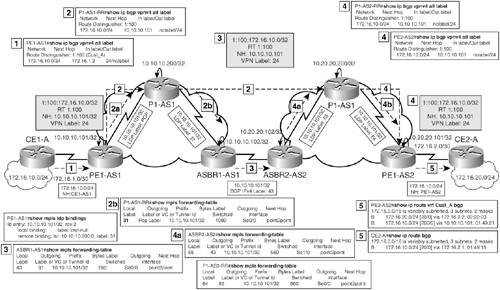
|
|
Step 2. |
Verify data forwarding – Figure 7-30 shows the data forwarding path taken by 172.16.20.1 to reach 172.16.10.1. Figure 7-30. Verify Data Forwarding Using Option 3 
|
|
Step 3. |
Verify end-to-end connectivity via ping – Verify end-to-end connectivity between Customer A networks (172.16.10.0/24 and 172.16.20.0/24) and Customer B networks (192.168.10.0/24 and 192.168.20.0/24). Example 7-22 shows the result of the ping operation. Example 7-22. Verify End-to-End Connectivity CE1-A#ping 172.16.20.1 source 172.16.10.1 Type escape sequence to abort. Sending 5, 100-byte ICMP Echos to 172.16.20.1, timeout is 2 seconds: Packet sent with a source address of 172.16.10.1 !!!!! Success rate is 100 percent (5/5), round-trip min/avg/max = 140/140/140 ms __________________________________________________________________________ CE1-B#ping 192.168.20.1 source 192.168.10.1 Type escape sequence to abort. Sending 5, 100-byte ICMP Echos to 192.168.20.1, timeout is 2 seconds: Packet sent with a source address of 192.168.10.1 !!!!! Success rate is 100 percent (5/5), round-trip min/avg/max = 132/138/140 ms |
MPLS Overview
- MPLS Overview
- Unicast IP Forwarding in Traditional IP Networks
- Overview of MPLS Forwarding
- MPLS Terminology
- MPLS Control and Data Plane Components
- MPLS Operation
- Special Outgoing Label Types
- Penultimate Hop Popping
- Frame-Mode MPLS
- Cell-Mode MPLS
Basic MPLS Configuration
- Basic MPLS Configuration
- Frame-Mode MPLS Configuration and Verification
- Cell-Mode MPLS over ATM Overview, Configuration, and Verification
- Command Reference
Basic MPLS VPN Overview and Configuration
- Basic MPLS VPN Overview and Configuration
- VPN Categories
- MPLS VPN Architecture and Terminology
- MPLS VPN Routing Model
- MPLS VPN Basic Configuration
- Outbound Route Filters
- Command Reference
PE-CE Routing Protocol-Static and RIP
- PE-CE Routing Protocol-Static and RIP
- Static PE-CE Routing Overview, Configuration, and Verification
- Static PE-CE Routing Command Reference
- RIPv2 PE-CE Routing Overview, Configuration, and Verification
- RIPv1 PE-CE Routing Configuration and Verification
- RIP PE-CE Routing Command Reference
PE-CE Routing Protocol-OSPF and EIGRP
- PE-CE Routing Protocol-OSPF and EIGRP
- OSPF PE-CE Routing Protocol Overview, Configuration and Verification
- EIGRP PE-CE Routing Protocol Overview, Configuration, and Verification
Implementing BGP in MPLS VPNs
- Implementing BGP in MPLS VPNs
- BGP PE-CE Routing Protocol Overview, Configuration, and Verification
- Implementing Route-Reflectors in MPLS VPN Networks
- Case Study-Hub and Spoke MPLS VPN Network Using BGP PE-CE Routing for Sites Using Unique AS Numbers
- Case Study-Hub and Spoke MPLS VPN Network with Sites Using Same AS Numbers
- Command Reference
Inter-Provider VPNs
- Inter-Provider VPNs
- Overview of Inter-Provider VPNs
- Option 1: Inter-Provider VPN Using Back-to-Back VRF Method
- Option 2: Inter-Provider VPNs Using ASBR-to-ASBR Approach
- Option 3: Multi-Hop MP-eBGP Between RR and eBGP Between ASBRs
- Option 4: Non-VPN Transit Provider
- Case Study-Inter-AS Implementing Route-Reflector and BGP Confederation in Provider Networks
- Case Study-Multi-Homed Inter-AS Provider Network
- Command Reference
Carrier Supporting Carriers
- Carrier Supporting Carriers
- Carrier Supporting Carriers Overview
- Deployment Scenarios with CSC Architecture
- CSC Architecture Benefits
- Command Reference
MPLS Traffic Engineering
- MPLS Traffic Engineering
- TE Basics
- MPLS TE Theory
- Constraint-Based Routing and Operation in MPLS TE
- Configuring MPLS TE
- Command Reference
Implementing VPNs with Layer 2 Tunneling Protocol Version 3
- Implementing VPNs with Layer 2 Tunneling Protocol Version 3
- L2TPv3 Overview
- Configuring L2TPv3 Tunnels for Layer 2 VPN
- Configuring L2TPv3 Static Tunnels
- Configuring L2TPv3 Dynamic Tunnels
- Implementing Layer 3 VPNs over L2TPv3 Tunnels
- Command Reference
Any Transport over MPLS (AToM)
- Any Transport over MPLS (AToM)
- Introduction to Layer 2 VPNs
- Implementing AToM for Like to Like Circuits
- L2 VPN-Any to Any Interworking
- Local Switching
- Command Reference
Virtual Private LAN Service (VPLS)
- Virtual Private LAN Service (VPLS)
- VPLS Overview
- VPLS Topology-Single PE or Direct Attachment
- Hierarchical VPLS-Distributed PE Architecture
- Command Reference
Implementing Quality of Service in MPLS Networks
- Implementing Quality of Service in MPLS Networks
- Introduction to QoS-Classification and Marking
- MPLS QoS Implementation
- MPLS QoS Operating Modes
- Modular QoS CLI: Configuration of QoS on Cisco Routers
- Configuration and Implementation of MPLS QoS in Uniform Mode and Short Pipe Mode Operation
- Implementing MPLS QoS for Layer 2 VPN Implementations
- Command Reference
MPLS Features and Case Studies
- MPLS Features and Case Studies
- Case Study 1: Implementing Multicast Support for MPLS VPNs
- Case Study 2: Implementing Multi-VRF CE, VRF Selection Using Source IP Address, VRF Selection Using Policy-Based Routing, NAT and HSRP Support in MPLS VPN, and Multicast VPN Support over Multi-VRF CE
- Case Study 3: Implementing Layer 2 VPNs over Inter-AS Topologies Using Layer 2 VPN Pseudo-Wire Switching
- Case Study 4: Implementing Layer 3 VPNs over Layer 2 VPN Topologies and Providing L2 VPN Redundancy
- Case Study 5: Implementing Dynamic Layer 3 VPNs Using mGRE Tunnels
- Case Study 6: Implementing Class-Based Tunnel Selection with MPLS Traffic Engineering
- Case Study 7: Implementing Hub and Spoke Topologies with OSPF
- Case Study 8: Implementing Hub and Spoke Topologies with EIGRP
- Case Study 9: Implementing VPLS Services with the GSR 12000 Series
- Case Study 10: BGP Site of Origin
- Command Reference
EAN: 2147483647
Pages: 130
