MPLS VPN Basic Configuration
This section outlines the generic configurations required on the routers in the service provider domain to implement MPLS VPN. The configurations of the PE and P routers will be covered in this section. The subsequent sections in this chapter delve into each of the configuration blocks on the PE and P routers alone. The configurations required to implement PE-CE routing sessions are discussed in Chapters 4 through 6, depending on the PE-CE protocol in use.
All configurations outlined in the following sections are performed in the network shown in Figure 3-11. For simplicity, only connected networks that are part of the VRF will be redistributed into the MP-BGP processes.
Figure 3-11. Network Topology: MPLS VPN PE and P Configuration
The topology in Figure 3-11 attempts to implement a simple intranet VPN between two sites belonging to Customer A, site 1 and site 2. The customer network consists of the CE routers CE1-A and CE2-A. In addition, two loopbacks (loopback 1) on PE1-AS1 and PE2-AS1 will be configured as part of the VRF CustomerA and be redistributed into the MP-BGP routing contexts.
Configuration of CE Routers
The configuration of route exchange between PE and CE routers involves the implementation of a routing protocol (or static/default routes) on the CE routers. No specific configuration other than the regular routing protocol configuration is required on the CE routers. On the PE router, VRF routing contexts (or address family contexts) are required for route exchange between the PE and CE. These routes are then mutually redistributed with the MP-BGP process per VRF. Configurations for the above based on protocol choice between PE and CE will be covered in Chapters 4 through 6.
Configuring MPLS Forwarding and VRF Definition on PE Routers
Configuring MPLS forwarding is the first step to provision the service provider's MPLS VPN backbone. This step ensures the service provider's readiness to provide MPLS-related services to prospective customers. At a minimum, the steps to configure MPLS forwarding on PE routers are
|
Step 1. |
Enable CEF. |
|
Step 2. |
Configure IGP routing protocol on the PE router. |
|
Step 3. |
Configure MPLS or label forwarding on the PE interfaces connected to P. |
These steps have already been discussed in Chapters 1 and 2 and thus have not been shown.
In this section, we configure VRFs on the PE routers. Figure 3-12 shows the configuration steps on the PE routers to configure VRF definition.
Figure 3-12. VRF Definition on PE Routers: Configuration Steps
|
Step 1. |
Configure VRF on PE router – Configure the VRF CustomerA on PE1 and PE2-AS1 router. This results in the creation of a VRF routing table and a Cisco Express Forwarding (CEF) table for CustomerA. Example 3-1 shows CustomerA VRF being configured on PE1-AS1 router. Note the VRF name is case sensitive. Example 3-1. VRF Definition PE1-AS1(config)#ip vrf CustomerA Note that creation or deletion of a VRF results in removal of the IP address from the interface. Example 3-2 illustrates the message that occurs on VRF deletion. Example 3-2. VRF Deletion PE1-AS1(config-vrf)#no ip vrf CustomerA % IP addresses from all interfaces in VRF CustomerA have been removed |
|
Step 2. |
Configure the RD – The RD creates routing and forwarding tables. The RD is added to the beginning of the customer's IPv4 prefixes to convert them into globally unique VPNv4 prefixes. Example 3-3 shows the configuration for defining the RD under the VRF. Example 3-3. Configuring VRF Parameters: RD PE1-AS1(config-vrf)#rd 1:100 The RD can be used in either of these formats: - 16-bit AS number: Your 32-bit number (for example, 1:100) - 32-bit IP address: Your 16-bit number (for example, 10.10.10.101:1) RD for an existing VRF can be changed only after deletion of that VRF. Example 3-4 illustrates the concept.Example 3-4. Redefining VRF RD Value PE1-AS1(config)#ip vrf CustomerA PE1-AS1(config-vrf)#rd 1:100 % Do "no ip vrf " before redefining the VRF RD has to be unique for that particular VRF. No two VRFs on the same router can have similar RD. Trying to set the same RD on the VRF on the same router results in the message shown in Example 3-5. Example 3-5. RD Uniqueness PE1-AS1(config)#ip vrf CustomerA PE1-AS1(config-vrf)#rd 1:100 % Cannot set RD, check if it's unique |
|
Step 3. |
Configure the import and export policy – Configure the import and export policy for the MP-BGP extended communities. The policy is used for filtering routes for that particular RT. Example 3-6 provides the relevant configuration for defining import and export policy. Example 3-6. Configuring VRF Parameters: RT PE1-AS1(config-vrf)#route-target both 1:100 The both keyword in the previous command results in the configuration of import and export policy, and the configuration output is shown in Example 3-7. Example 3-7. RT Configuration Options PE1-AS1#sh run Building configuration... ip vrf CustomerA rd 1:100 route-target export 1:100 route-target import 1:100 |
|
Step 4. |
Associate VRF with the interface – Associate virtual routing/forwarding instance (VRF) with an interface or subinterface in this CustomerA. Example 3-8. Associating VRF with Interface PE1-AS1(config)#interface serial4/0 PE1-AS1(config-if)#ip add 172.16.1.1 255.255.255.252 PE1-AS1(config-if)# ip vrf forwarding CustomerA % Interface Serial4/0 IP address 172.16.1.1 removed due to enabling VRF CustomerA PE1-AS1(config-if)#ip add 172.16.1.1 255.255.255.252 Example 3-9. VRF Association to Interface IP Address PE1-AS1(config-if)#no ip vrf forwarding CustomerA % Interface Serial4/0 IP address 172.16.1.1 removed due to disabling VRF CustomerA |
Final VRF Configuration on PE1-AS1 Router
Example 3-10 shows the VRF configuration on the PE1-AS1 router.
Example 3-10. VRF Configuration of PE1-AS1
ip vrf CustomerA

 rd 1:100

 route-target export 1:100

 route-target import 1:100

!

interface Serial1/0

 description PE-CE link to CE1-A

 ip vrf forwarding CustomerA

 ip address 172.16.1.1 255.255.255.0

!

Interface Loopback1

 ip vrf forwarding CustomerA

 ip address 172.16.100.1 255.255.255.255
Verification of VRF Configuration on PE Routers
The show ip vrf command is used to verify if the correct VRF exists on the interface. Example 3-11 indicates that the correct VRF CustomerA is configured on the Serial1/0 interface on the PE1 router.
Example 3-11. show ip vrf on PE1-AS1
PE1-AS1#show ip vrf

 Name Default RD Interfaces

 CustomerA 1:100 Se1/0

 Lo1
The show ip vrf interfaces command provides the listing of interfaces that are activated for a particular VRF. Example 3-12 shows that Serial1/0 is active for VRF VRF-Static.
Example 3-12. show ip vrf interfaces on PE1-AS1
PE1-AS1#show ip vrf interfaces

Interface IP-Address VRF Protocol

Serial1/0 172.16.1.1 CustomerA up

Lo1 172.16.100.1 CustomerA up
Configuration of BGP PE-PE Routing on PE Routers
Configuring BGP PE-PE routing between the PE routers is the next step in an MPLS VPN deployment. The purpose of this step is to ensure that VPNv4 routes can be transported across the service provider backbone using MP-iBGP. The P router is transparent to this entire process and, therefore, does not carry any customer routes. Figure 3-13 illustrates the steps for configuring BGP PE-PE routing sessions between the PE routers.
Figure 3-13. BGP PE-PE Routing Configuration Steps
|
Step 1. |
Configure BGP routing on PE routers – Enable BGP routing and identify the AS on the PE1-AS1 and PE2-AS1 routers. Example 3-13 highlights the configuration. Example 3-13. Configuring BGP Routing on PE Routers PE1-AS1(config)#router bgp 1 ________________________________________________________________ PE2-AS1(config)#router bgp 1 |
|
Step 2. |
Configure the MP-iBGP neighbors – Configure the remote MP-iBGP neighbor and use the loopback interface as the source of BGP messages and updates. Note that you have to use the update-source command only when the neighbor is peering to your loopback address. This is irrespective of whether it is an iBGP or eBGP neighbor. Example 3-14 shows the configuration for the PE1-AS1 and PE2-AS1 router. Example 3-14. Configuring MP-iBGP Neighbors PE1-AS1(config-router)#neighbor 10.10.10.102 remote-as 1 PE1-AS1(config-router)#neighbor 10.10.10.102 update-source loopback0 ________________________________________________________________ PE2-AS1(config-router)#neighbor 10.10.10.101 remote-as 1 PE2-AS1(config-router)#neighbor 10.10.10.101 update-source loopback0 |
|
Step 3. |
Configure the VPNv4 address family – Configure the address family for VPNv4 under the BGP configuration process. This step allows you to enter the VPNv4 address family to activate the VPNv4 neighbors. Activate the iBGP neighbor, which is essential for transporting VPNv4 prefixes across the service provider backbone. Using next-hop-self is optional and is primarily used when the service provider has an eBGP PE-CE routing with the customers, because internal BGP (iBGP) sessions preserve the next-hop attribute learned from eBGP peers, which is why it is important to have an internal route to the next hop. Otherwise, the BGP route is unreachable. To make sure you can reach the eBGP next hop, include the network that the next hop belongs to in the IGP or use the next-hop-self neighbor command to force the router to advertise itself, rather than the external peer, as the next hop. Example 3-15. Configuring BGP VPNv4 Address Family PE1-AS1(config-router)#address-family vpnv4 PE1-AS1(config-router-af)# neighbor 10.10.10.102 activate PE1-AS1(config-router-af)# neighbor 10.10.10.102 send-community extended _________________________________________________________________________ PE2-AS1(config-router)#address-family vpnv4 PE2-AS1(config-router-af)# neighbor 10.10.10.101 activate PE2-AS1(config-router-af)# neighbor 10.10.10.101 send-community extended |
|
Step 4. |
Configure the IPv4 address family – Configure the peer VRF IPv4 address family under the BGP configuration process. This step allows you to enter the IPv4 networks that will be converted to VPNv4 routes in MP-BGP updates. In Chapters 4, 5, and 6, the individual PE-CE routing protocol interaction configuration involving redistribution of PE-CE routing protocol contexts or instances will be configured in the IPv4 address family per VRF under the BGP process. For simplicity, redistribution of all connected networks is configured into the MP-BGP process. Example 3-16 shows the configuration on PE1-AS1 and PE2-AS1 routers. Example 3-16. Configuring BGP per VRF IPv4 Address Family (Routing Context) PE1-AS1(config-router)#address-family ipv4 vrf CustomerA PE1-AS1(config-router-af)# redistribute connected PE1-AS1(config-router-af)# exit-address-family _______________________________________________________________ PE2-AS1(config-router)#address-family ipv4 vrf CustomerA PE2-AS1(config-router-af)# redistribute connected PE2-AS1(config-router-af)# exit-address-family |
BGP PE-PE Routing Final Configuration on PE1-AS1 and PE2-AS1 Router
Example 3-17 shows the final BGP PE-PE routing configuration on the PE1-AS1 and PE2-AS1 router.
Example 3-17. BGP PE-PE Configurations of PE1-AS1 and PE2-AS1 Routers
!PE1-AS1 Router:

router bgp 1

 no synchronization

 neighbor 10.10.10.102 remote-as 1

 no auto-summary

 !

 address-family vpnv4

 neighbor 10.10.10.102 activate

 neighbor 10.10.10.102 send-community extended

 exit-address-family

!

address-family ipv4 vrf CustomerA

 redistribute connected

 no auto-summary

 no synchronization

 exit-address-family

__________________________________________________________________________

!PE2-AS1 Router:

router bgp 1

 no synchronization

 bgp log-neighbor-changes

 neighbor 10.10.10.101 remote-as 1

 neighbor 10.10.10.101 update-source Loopback0

 no auto-summary

 !

 address-family vpnv4

 neighbor 10.10.10.101 activate

 neighbor 10.10.10.101 send-community extended

 exit-address-family

!

address-family ipv4 vrf CustomerA

 redistribute connected

 no auto-summary

 no synchronization

 exit-address-family
Verification and Monitoring of BGP PE-PE Routing on PE Routers
After configuring BGP PE-PE routing between the PE routers, you can verify that the MP-iBGP neighbors are operational by issuing any of the following commands:
- show ip bgp vpnv4 * summary
- show IP bgp vpnv4 all
- show ip bgp summary
- show ip bgp neighbor ip-address
Example 3-18 shows that the VPNv4 neighbor relationship is formed.
Example 3-18. VPN Neighbor Relationship Verification
PE1#show ip bgp vpnv4 all summary

BGP router identifier 10.10.10.101, local AS number 1

BGP table version is 7, main routing table version 7


Neighbor V AS MsgRcvd MsgSent TblVer InQ OutQ Up/Down State/PfxRcd

10.10.10.102 4 1 202 200 7 0 0 00:00:39 0

__________________________________________________________________________________

PE2#show ip bgp vpnv4 all summary

BGP router identifier 10.10.10.102, local AS number 1

BGP table version is 1, main routing table version 1


Neighbor V AS MsgRcvd MsgSent TblVer InQ OutQ Up/Down State/PfxRcd

10.10.10.101 4 1 11 11 1 0 0 00:07:16 0
Configuration of P Router
No special configurations need to be performed on the P routers P1-AS1 and P1-AS2 for MPLS VPN support. Because the P routers only participate in MPLS labeled packet forwarding, the only requirements are those of an LSR in an MPLS network, namely, IGP for NLRI exchange and LDP for label assignment and distribution. As always, CEF needs to be enabled on all interfaces configured for MPLS forwarding. Configuration of the P1-AS1 router is shown in Example 3-19.
Example 3-19. P1-AS1 Configuration
mpls ldp router-id loopback0

!

interface Serial0/0

 ip address 10.10.10.2 255.255.255.252

 mpls ip

!

interface Serial1/0

 ip address 10.10.10.5 255.255.255.252

 mpls ip

!

Interface loopback0

 ip address 10.10.10.200 255.255.255.255

!

router ospf 1

network 10.0.0.0 0.255.255.255 area 0

!
Label Verification and Control and Data Plane Operation
After configuring devices in the network as per the previous steps, the verification of label allocation and propagation can be performed on the PE and P routers using the commands described in Figure 3-14.
Figure 3-14. Label Allocation Verification and Control/Data Plane Operation
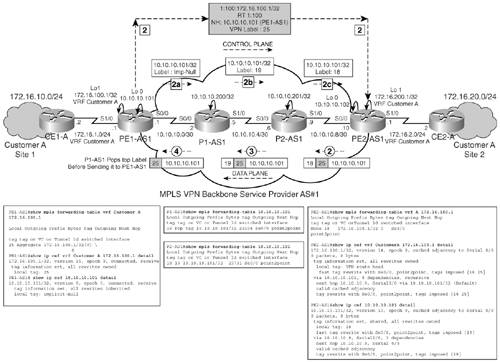
The control plane and data plane operation for network 172.16.100.1 as part of VRF CustomerA is depicted in Figure 3-14. Note that the outgoing label mapped to prefix 172.16.100.1 on PE1-AS1 is aggregate and not untagged. For all networks that are directly connected to the PE router (like loopbacks or interface IP networks) that are part of a VRF, the outgoing label mapped in the LFIB is the aggregate label. If, however, the incoming VPN packet is to be forwarded to a next-hop address (like that of a connected CE router), the outgoing label mapping is untagged. Thus, aggregate and untagged labels that were explained in Chapter 1 are encountered in MPLS VPN implementations.
MPLS Overview
- MPLS Overview
- Unicast IP Forwarding in Traditional IP Networks
- Overview of MPLS Forwarding
- MPLS Terminology
- MPLS Control and Data Plane Components
- MPLS Operation
- Special Outgoing Label Types
- Penultimate Hop Popping
- Frame-Mode MPLS
- Cell-Mode MPLS
Basic MPLS Configuration
- Basic MPLS Configuration
- Frame-Mode MPLS Configuration and Verification
- Cell-Mode MPLS over ATM Overview, Configuration, and Verification
- Command Reference
Basic MPLS VPN Overview and Configuration
- Basic MPLS VPN Overview and Configuration
- VPN Categories
- MPLS VPN Architecture and Terminology
- MPLS VPN Routing Model
- MPLS VPN Basic Configuration
- Outbound Route Filters
- Command Reference
PE-CE Routing Protocol-Static and RIP
- PE-CE Routing Protocol-Static and RIP
- Static PE-CE Routing Overview, Configuration, and Verification
- Static PE-CE Routing Command Reference
- RIPv2 PE-CE Routing Overview, Configuration, and Verification
- RIPv1 PE-CE Routing Configuration and Verification
- RIP PE-CE Routing Command Reference
PE-CE Routing Protocol-OSPF and EIGRP
- PE-CE Routing Protocol-OSPF and EIGRP
- OSPF PE-CE Routing Protocol Overview, Configuration and Verification
- EIGRP PE-CE Routing Protocol Overview, Configuration, and Verification
Implementing BGP in MPLS VPNs
- Implementing BGP in MPLS VPNs
- BGP PE-CE Routing Protocol Overview, Configuration, and Verification
- Implementing Route-Reflectors in MPLS VPN Networks
- Case Study-Hub and Spoke MPLS VPN Network Using BGP PE-CE Routing for Sites Using Unique AS Numbers
- Case Study-Hub and Spoke MPLS VPN Network with Sites Using Same AS Numbers
- Command Reference
Inter-Provider VPNs
- Inter-Provider VPNs
- Overview of Inter-Provider VPNs
- Option 1: Inter-Provider VPN Using Back-to-Back VRF Method
- Option 2: Inter-Provider VPNs Using ASBR-to-ASBR Approach
- Option 3: Multi-Hop MP-eBGP Between RR and eBGP Between ASBRs
- Option 4: Non-VPN Transit Provider
- Case Study-Inter-AS Implementing Route-Reflector and BGP Confederation in Provider Networks
- Case Study-Multi-Homed Inter-AS Provider Network
- Command Reference
Carrier Supporting Carriers
- Carrier Supporting Carriers
- Carrier Supporting Carriers Overview
- Deployment Scenarios with CSC Architecture
- CSC Architecture Benefits
- Command Reference
MPLS Traffic Engineering
- MPLS Traffic Engineering
- TE Basics
- MPLS TE Theory
- Constraint-Based Routing and Operation in MPLS TE
- Configuring MPLS TE
- Command Reference
Implementing VPNs with Layer 2 Tunneling Protocol Version 3
- Implementing VPNs with Layer 2 Tunneling Protocol Version 3
- L2TPv3 Overview
- Configuring L2TPv3 Tunnels for Layer 2 VPN
- Configuring L2TPv3 Static Tunnels
- Configuring L2TPv3 Dynamic Tunnels
- Implementing Layer 3 VPNs over L2TPv3 Tunnels
- Command Reference
Any Transport over MPLS (AToM)
- Any Transport over MPLS (AToM)
- Introduction to Layer 2 VPNs
- Implementing AToM for Like to Like Circuits
- L2 VPN-Any to Any Interworking
- Local Switching
- Command Reference
Virtual Private LAN Service (VPLS)
- Virtual Private LAN Service (VPLS)
- VPLS Overview
- VPLS Topology-Single PE or Direct Attachment
- Hierarchical VPLS-Distributed PE Architecture
- Command Reference
Implementing Quality of Service in MPLS Networks
- Implementing Quality of Service in MPLS Networks
- Introduction to QoS-Classification and Marking
- MPLS QoS Implementation
- MPLS QoS Operating Modes
- Modular QoS CLI: Configuration of QoS on Cisco Routers
- Configuration and Implementation of MPLS QoS in Uniform Mode and Short Pipe Mode Operation
- Implementing MPLS QoS for Layer 2 VPN Implementations
- Command Reference
MPLS Features and Case Studies
- MPLS Features and Case Studies
- Case Study 1: Implementing Multicast Support for MPLS VPNs
- Case Study 2: Implementing Multi-VRF CE, VRF Selection Using Source IP Address, VRF Selection Using Policy-Based Routing, NAT and HSRP Support in MPLS VPN, and Multicast VPN Support over Multi-VRF CE
- Case Study 3: Implementing Layer 2 VPNs over Inter-AS Topologies Using Layer 2 VPN Pseudo-Wire Switching
- Case Study 4: Implementing Layer 3 VPNs over Layer 2 VPN Topologies and Providing L2 VPN Redundancy
- Case Study 5: Implementing Dynamic Layer 3 VPNs Using mGRE Tunnels
- Case Study 6: Implementing Class-Based Tunnel Selection with MPLS Traffic Engineering
- Case Study 7: Implementing Hub and Spoke Topologies with OSPF
- Case Study 8: Implementing Hub and Spoke Topologies with EIGRP
- Case Study 9: Implementing VPLS Services with the GSR 12000 Series
- Case Study 10: BGP Site of Origin
- Command Reference
EAN: 2147483647
Pages: 130
