Overview of MPLS Forwarding
In MPLS enabled networks, packets are forwarded based on labels. These labels might correspond to IP destination addresses or to other parameters, such as QoS classes and source address. Labels are generated per router (and in some cases, per interface on a router) and bear local significance to the router generating them. Routers assign labels to define paths called Label Switched Paths (LSP) between endpoints. Because of this, only the routers on the edge of the MPLS network perform a routing lookup.
Figure 1-2 illustrates the same network as depicted in Figure 1-1 with MPLS forwarding where route table lookups are performed only by MPLS edge border routers, R1 and R4. The routers in MPLS network R1, R2, and R3 propagate updates for 172.16.10.0/24 network via an IGP routing protocol just like in traditional IP networks, assuming no filters or summarizations are not configured. This leads to the creation of an IP forwarding table. Also, because the links connecting the routers are MPLS enabled, they assign local labels for destination 172.16.10.0 and propagate them upstream to their directly connected peers using a label distribution protocol; for example, R1 assigns a local label L1 and propagates it to the upstream neighbor R2. R2 and R3 similarly assign labels and propagate the same to upstream neighbors R3 and R4, respectively. Consequently, as illustrated in Figure 1-2, the routers now maintain a label forwarding table to enable labeled packet forwarding in addition to the IP routing table. The concept of upstream and downstream is explained in greater detail in the section "MPLS Terminology."
Figure 1-2. Forwarding in the MPLS Domain
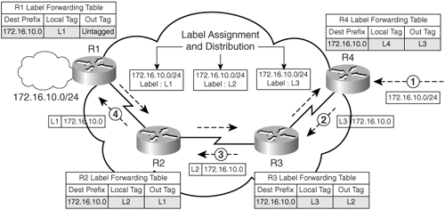
As shown in Figure 1-2, the following process takes place in the data forwarding path from R4 to R1:
|
1. |
R4 receives a data packet for network 172.16.10.0 and identifies that the path to the destination is MPLS enabled. Therefore, R4 forwards the packet to next-hop Router R3 after applying a label L3 (from downstream Router R3) on the packet and forwards the labeled packet to R3. |
|
2. |
R3 receives the labeled packet with label L3 and swaps the label L3 with L2 and forwards the packet to R2. |
|
3. |
R2 receives the labeled packet with label L2 and swaps the label L2 with L1 and forwards the packet to R1. |
|
4. |
R1 is the border router between the IP and MPLS domains; therefore, R1 removes the labels on the data packet and forwards the IP packet to destination network 172.16.10.0. |
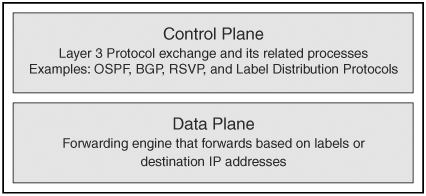
Architectural Blocks of MPLS
MPLS functionality on Cisco devices is divided into two main architectural blocks:
- Control plane – Performs functions related to identifying reachability to destination prefixes. Therefore, the control plane contains all the Layer 3 routing information, as well as the processes within, to exchange reachability information for a specific Layer 3 prefix. Common examples of control plane functions are routing protocol information exchange like in OSPF and BGP. Hence, IP routing information exchange is a control plane function. In addition, all protocol functions that are responsible for the exchange of labels between neighboring routers function in the control plane as in label distribution protocols (explained in detail in section "LDP Session Establishment").
- Data plane – Performs the functions relating to forwarding data packets. These packets can be either Layer 3 IP packets or labeled IP packets. The information in the data plane, such as label values, are derived from the control plane. Information exchange between neighboring routers creates mappings of IP destination prefixes to labels in the control plane, which is used to forward data plane labeled packets.
Figure 1-3 depicts the control plane and data plane functions.
Figure 1-3. Control Plane and Data Plane on a Router
MPLS Overview
- MPLS Overview
- Unicast IP Forwarding in Traditional IP Networks
- Overview of MPLS Forwarding
- MPLS Terminology
- MPLS Control and Data Plane Components
- MPLS Operation
- Special Outgoing Label Types
- Penultimate Hop Popping
- Frame-Mode MPLS
- Cell-Mode MPLS
Basic MPLS Configuration
- Basic MPLS Configuration
- Frame-Mode MPLS Configuration and Verification
- Cell-Mode MPLS over ATM Overview, Configuration, and Verification
- Command Reference
Basic MPLS VPN Overview and Configuration
- Basic MPLS VPN Overview and Configuration
- VPN Categories
- MPLS VPN Architecture and Terminology
- MPLS VPN Routing Model
- MPLS VPN Basic Configuration
- Outbound Route Filters
- Command Reference
PE-CE Routing Protocol-Static and RIP
- PE-CE Routing Protocol-Static and RIP
- Static PE-CE Routing Overview, Configuration, and Verification
- Static PE-CE Routing Command Reference
- RIPv2 PE-CE Routing Overview, Configuration, and Verification
- RIPv1 PE-CE Routing Configuration and Verification
- RIP PE-CE Routing Command Reference
PE-CE Routing Protocol-OSPF and EIGRP
- PE-CE Routing Protocol-OSPF and EIGRP
- OSPF PE-CE Routing Protocol Overview, Configuration and Verification
- EIGRP PE-CE Routing Protocol Overview, Configuration, and Verification
Implementing BGP in MPLS VPNs
- Implementing BGP in MPLS VPNs
- BGP PE-CE Routing Protocol Overview, Configuration, and Verification
- Implementing Route-Reflectors in MPLS VPN Networks
- Case Study-Hub and Spoke MPLS VPN Network Using BGP PE-CE Routing for Sites Using Unique AS Numbers
- Case Study-Hub and Spoke MPLS VPN Network with Sites Using Same AS Numbers
- Command Reference
Inter-Provider VPNs
- Inter-Provider VPNs
- Overview of Inter-Provider VPNs
- Option 1: Inter-Provider VPN Using Back-to-Back VRF Method
- Option 2: Inter-Provider VPNs Using ASBR-to-ASBR Approach
- Option 3: Multi-Hop MP-eBGP Between RR and eBGP Between ASBRs
- Option 4: Non-VPN Transit Provider
- Case Study-Inter-AS Implementing Route-Reflector and BGP Confederation in Provider Networks
- Case Study-Multi-Homed Inter-AS Provider Network
- Command Reference
Carrier Supporting Carriers
- Carrier Supporting Carriers
- Carrier Supporting Carriers Overview
- Deployment Scenarios with CSC Architecture
- CSC Architecture Benefits
- Command Reference
MPLS Traffic Engineering
- MPLS Traffic Engineering
- TE Basics
- MPLS TE Theory
- Constraint-Based Routing and Operation in MPLS TE
- Configuring MPLS TE
- Command Reference
Implementing VPNs with Layer 2 Tunneling Protocol Version 3
- Implementing VPNs with Layer 2 Tunneling Protocol Version 3
- L2TPv3 Overview
- Configuring L2TPv3 Tunnels for Layer 2 VPN
- Configuring L2TPv3 Static Tunnels
- Configuring L2TPv3 Dynamic Tunnels
- Implementing Layer 3 VPNs over L2TPv3 Tunnels
- Command Reference
Any Transport over MPLS (AToM)
- Any Transport over MPLS (AToM)
- Introduction to Layer 2 VPNs
- Implementing AToM for Like to Like Circuits
- L2 VPN-Any to Any Interworking
- Local Switching
- Command Reference
Virtual Private LAN Service (VPLS)
- Virtual Private LAN Service (VPLS)
- VPLS Overview
- VPLS Topology-Single PE or Direct Attachment
- Hierarchical VPLS-Distributed PE Architecture
- Command Reference
Implementing Quality of Service in MPLS Networks
- Implementing Quality of Service in MPLS Networks
- Introduction to QoS-Classification and Marking
- MPLS QoS Implementation
- MPLS QoS Operating Modes
- Modular QoS CLI: Configuration of QoS on Cisco Routers
- Configuration and Implementation of MPLS QoS in Uniform Mode and Short Pipe Mode Operation
- Implementing MPLS QoS for Layer 2 VPN Implementations
- Command Reference
MPLS Features and Case Studies
- MPLS Features and Case Studies
- Case Study 1: Implementing Multicast Support for MPLS VPNs
- Case Study 2: Implementing Multi-VRF CE, VRF Selection Using Source IP Address, VRF Selection Using Policy-Based Routing, NAT and HSRP Support in MPLS VPN, and Multicast VPN Support over Multi-VRF CE
- Case Study 3: Implementing Layer 2 VPNs over Inter-AS Topologies Using Layer 2 VPN Pseudo-Wire Switching
- Case Study 4: Implementing Layer 3 VPNs over Layer 2 VPN Topologies and Providing L2 VPN Redundancy
- Case Study 5: Implementing Dynamic Layer 3 VPNs Using mGRE Tunnels
- Case Study 6: Implementing Class-Based Tunnel Selection with MPLS Traffic Engineering
- Case Study 7: Implementing Hub and Spoke Topologies with OSPF
- Case Study 8: Implementing Hub and Spoke Topologies with EIGRP
- Case Study 9: Implementing VPLS Services with the GSR 12000 Series
- Case Study 10: BGP Site of Origin
- Command Reference
EAN: 2147483647
Pages: 130
