Case Study 3: Implementing Layer 2 VPNs over Inter-AS Topologies Using Layer 2 VPN Pseudo-Wire Switching
Case Study 3 Implementing Layer 2 VPNs over Inter AS Topologies Using Layer 2 VPN Pseudo Wire Switching
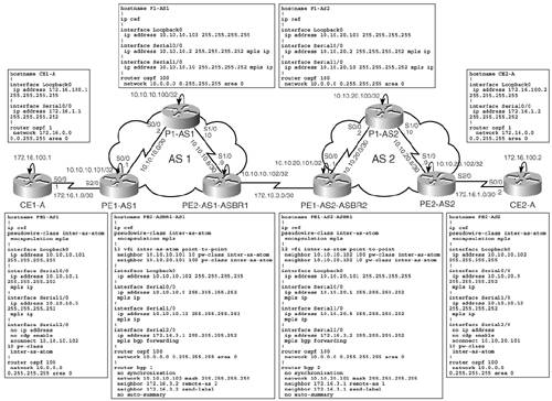
Service providers SP1 and SP2 are required by Customer A to provide Layer 2 VPN connectivity between multiple sites belonging to Customer A, as illustrated in Figure 14-22.
Figure 14-22. Case Study 3 Topology and Base Configurations
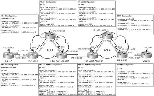
To enable the implementation of Layer 2 VPN (AToM) over an Inter-AS topology, as shown in Figure 14-22, the ASBR Routers PE2-AS1-ASBR1 and PE1-AS2-ASBR1 are configured for layer2vpn pseudo-wire switching.
Figure 14-22 also outlines the basic configurations for the devices in the SP domain, namely, PE1-AS1, PE2-AS1-ASBR1, P1-AS1, PE2-AS2, PE1-AS2-ASBR1, P1-AS2, and CE routers CE1-A and CE2-A. It is assumed that MPLS forwarding has been enabled on the appropriate interfaces, and IP addressing performed as illustrated in Figure 14-22. The PE routers are configured for OSPF as the IGP. The ASBR routers are configured for Inter-AS implementation between one another. CE routers CE1-A and CE2-A are configured with OSPF process of 10 with all networks in area 0. Only the configurations on the routers to implement Inter-AS have been depicted. Note that the Inter-AS implementation uses IPv4 BGP for label distribution between AS boundaries. Configurations pertaining to the implementation of Layer 2 VPN pseudo-wire switching are shown later in this section.
Layer 2 VPN Pseudo-Wire Switching Theory and Configuration
Layer 2 VPN pseudo-wire switching enables extension of Layer 2 VPN pseudo-wires across an Inter-AS boundary or across two separate MPLS networks. Layer 2 VPN pseudo-wire switching connects two or more contiguous pseudo-wire segments to form an end-to-end multi-hop pseudo-wire. This end-to-end pseudo-wire functions as a single point-to-point pseudo-wire. Layer 2 VPN pseudo-wire switching enables the SP to keep the IP addresses of the edge PE routers private across Inter-AS boundaries, using the IP addresses of the ASBRs, the ASBRs join the pseudo wires of the two domains.
AToM packets forwarded between two pseudo wires are treated the same as any other MPLS packet excluding the following exceptions:
- The outgoing virtual circuit (VC) label replaces the incoming VC label in the packet. New Internal Gateway Protocol (IGP) labels and Layer 2 encapsulation are added.
- The incoming VC label Time To Live (TTL) field is decremented by one and copied to the outgoing VC label TTL field.
- The incoming VC label EXP value is copied to the outgoing VC label EXP field.
- The outgoing VC label "Bottom of Stack" S bit in the outgoing VC label is set to 1.
- AToM control word processing is not performed at the Layer 2 VPN pseudo-wire switching aggregation point or ASBR. Sequence numbers are not validated.
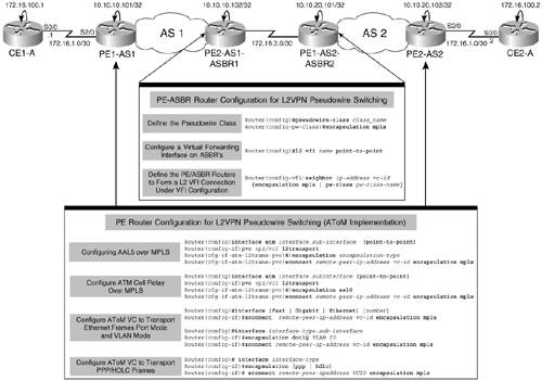
The configurations required on the PE routers in either domain, as well as the ASBRs implementing Inter-AS, are shown in the configuration flowchart in Figure 14-23.
Figure 14-23. Configuration Flowchart for PE and ASBR Routers to Implement Layer 2 VPN Pseudo-Wire Switching
Following the configuration flowchart shown in Figure 14-23, the additional configurations for the PE and PE-ASBR devices in Figure 14-22 are as illustrated in Figure 14-24.
Figure 14-24. Configuration in Case Study 3 for PE and ASBR Routers to Implement Layer 2 VPN Pseudo-Wire Switching
Verifications for Case Study 3
Figure 14-25 outlines the verification involved in the implementation of L2 VPN pseudo-wire switching on the PE, PE-ASBR, and CE routers in Case Study 3.
Figure 14-25. Case Study 3: Layer 2 VPN Pseudo-Wire Switching Verification
Final Configurations for Case Study 3
The final configurations for the devices in Case Study 3 are shown in Figure 14-26.
Figure 14-26. Case Study 3: Final Configurations
MPLS Overview
- MPLS Overview
- Unicast IP Forwarding in Traditional IP Networks
- Overview of MPLS Forwarding
- MPLS Terminology
- MPLS Control and Data Plane Components
- MPLS Operation
- Special Outgoing Label Types
- Penultimate Hop Popping
- Frame-Mode MPLS
- Cell-Mode MPLS
Basic MPLS Configuration
- Basic MPLS Configuration
- Frame-Mode MPLS Configuration and Verification
- Cell-Mode MPLS over ATM Overview, Configuration, and Verification
- Command Reference
Basic MPLS VPN Overview and Configuration
- Basic MPLS VPN Overview and Configuration
- VPN Categories
- MPLS VPN Architecture and Terminology
- MPLS VPN Routing Model
- MPLS VPN Basic Configuration
- Outbound Route Filters
- Command Reference
PE-CE Routing Protocol-Static and RIP
- PE-CE Routing Protocol-Static and RIP
- Static PE-CE Routing Overview, Configuration, and Verification
- Static PE-CE Routing Command Reference
- RIPv2 PE-CE Routing Overview, Configuration, and Verification
- RIPv1 PE-CE Routing Configuration and Verification
- RIP PE-CE Routing Command Reference
PE-CE Routing Protocol-OSPF and EIGRP
- PE-CE Routing Protocol-OSPF and EIGRP
- OSPF PE-CE Routing Protocol Overview, Configuration and Verification
- EIGRP PE-CE Routing Protocol Overview, Configuration, and Verification
Implementing BGP in MPLS VPNs
- Implementing BGP in MPLS VPNs
- BGP PE-CE Routing Protocol Overview, Configuration, and Verification
- Implementing Route-Reflectors in MPLS VPN Networks
- Case Study-Hub and Spoke MPLS VPN Network Using BGP PE-CE Routing for Sites Using Unique AS Numbers
- Case Study-Hub and Spoke MPLS VPN Network with Sites Using Same AS Numbers
- Command Reference
Inter-Provider VPNs
- Inter-Provider VPNs
- Overview of Inter-Provider VPNs
- Option 1: Inter-Provider VPN Using Back-to-Back VRF Method
- Option 2: Inter-Provider VPNs Using ASBR-to-ASBR Approach
- Option 3: Multi-Hop MP-eBGP Between RR and eBGP Between ASBRs
- Option 4: Non-VPN Transit Provider
- Case Study-Inter-AS Implementing Route-Reflector and BGP Confederation in Provider Networks
- Case Study-Multi-Homed Inter-AS Provider Network
- Command Reference
Carrier Supporting Carriers
- Carrier Supporting Carriers
- Carrier Supporting Carriers Overview
- Deployment Scenarios with CSC Architecture
- CSC Architecture Benefits
- Command Reference
MPLS Traffic Engineering
- MPLS Traffic Engineering
- TE Basics
- MPLS TE Theory
- Constraint-Based Routing and Operation in MPLS TE
- Configuring MPLS TE
- Command Reference
Implementing VPNs with Layer 2 Tunneling Protocol Version 3
- Implementing VPNs with Layer 2 Tunneling Protocol Version 3
- L2TPv3 Overview
- Configuring L2TPv3 Tunnels for Layer 2 VPN
- Configuring L2TPv3 Static Tunnels
- Configuring L2TPv3 Dynamic Tunnels
- Implementing Layer 3 VPNs over L2TPv3 Tunnels
- Command Reference
Any Transport over MPLS (AToM)
- Any Transport over MPLS (AToM)
- Introduction to Layer 2 VPNs
- Implementing AToM for Like to Like Circuits
- L2 VPN-Any to Any Interworking
- Local Switching
- Command Reference
Virtual Private LAN Service (VPLS)
- Virtual Private LAN Service (VPLS)
- VPLS Overview
- VPLS Topology-Single PE or Direct Attachment
- Hierarchical VPLS-Distributed PE Architecture
- Command Reference
Implementing Quality of Service in MPLS Networks
- Implementing Quality of Service in MPLS Networks
- Introduction to QoS-Classification and Marking
- MPLS QoS Implementation
- MPLS QoS Operating Modes
- Modular QoS CLI: Configuration of QoS on Cisco Routers
- Configuration and Implementation of MPLS QoS in Uniform Mode and Short Pipe Mode Operation
- Implementing MPLS QoS for Layer 2 VPN Implementations
- Command Reference
MPLS Features and Case Studies
- MPLS Features and Case Studies
- Case Study 1: Implementing Multicast Support for MPLS VPNs
- Case Study 2: Implementing Multi-VRF CE, VRF Selection Using Source IP Address, VRF Selection Using Policy-Based Routing, NAT and HSRP Support in MPLS VPN, and Multicast VPN Support over Multi-VRF CE
- Case Study 3: Implementing Layer 2 VPNs over Inter-AS Topologies Using Layer 2 VPN Pseudo-Wire Switching
- Case Study 4: Implementing Layer 3 VPNs over Layer 2 VPN Topologies and Providing L2 VPN Redundancy
- Case Study 5: Implementing Dynamic Layer 3 VPNs Using mGRE Tunnels
- Case Study 6: Implementing Class-Based Tunnel Selection with MPLS Traffic Engineering
- Case Study 7: Implementing Hub and Spoke Topologies with OSPF
- Case Study 8: Implementing Hub and Spoke Topologies with EIGRP
- Case Study 9: Implementing VPLS Services with the GSR 12000 Series
- Case Study 10: BGP Site of Origin
- Command Reference
EAN: 2147483647
Pages: 130
