VPN Categories
VPNs were originally introduced to enable service providers to use common physical infrastructure to implement emulated point-to-point links between customer sites. A customer network implemented with any VPN technology would contain distinct regions under the customer's control called the customer sites connected to each other via the service provider (SP) network. In traditional router-based networks, different sites belonging to the same customer were connected to each other using dedicated point-to-point links. The cost of implementation depended on the number of customer sites to be connected with these dedicated links. A full mesh of connected sites would consequently imply an exponential increase in the cost associated.
Frame Relay and ATM were the first technologies widely adopted to implement VPNs. These networks consisted of various devices, belonging to either the customer or the service provider, that were components of the VPN solution. Generically, the VPN realm would consist of the following regions:
- Customer network – Consisted of the routers at the various customer sites. The routers connecting individual customers' sites to the service provider network were called customer edge (CE) routers.
- Provider network – Used by the service provider to offer dedicated point-to-point links over infrastructure owned by the service provider. Service provider devices to which the CE routers were directly attached were called provider edge (PE) routers. In addition, the service provider network might consist of devices used for forwarding data in the SP backbone called provider (P) routers.
Depending on the service provider's participation in customer routing, the VPN implementations can be classified broadly into one of the following:
- Overlay model
- Peer-to-peer model
When Frame Relay and ATM provided customers with emulated private networks, the provider did not participate in customer routing. The service provider was only responsible for providing the customer with transport of customer data using virtual point-to-point links. As a result, the service provider would only provide customers with virtual circuit connectivity at Layer 2; this implementation was referred to as the Overlay model. If the virtual circuit was permanent or available for use by the customer at all times, it was called a permanent virtual circuit (PVC). If the circuit was established by the provider on-demand, it was called a switched virtual circuit (SVC). The primary drawback of an Overlay model was the full mesh of virtual circuits between all customer sites for optimal connectivity (except in the case of hub and spoke or partial hub and spoke deployments). If the number of customer sites was N, N(N-1)/2 was the total number of circuits that would be necessary for optimal routing.
Overlay VPNs were initially implemented by the SP by providing either Layer 1 (physical layer) connectivity or a Layer 2 transport circuit between customer sites. In the Layer 1 implementation, the SP would provide physical layer connectivity between customer sites, and the customer was responsible for all other layers. In the Layer 2 implementation (depicted in Figure 3-1), the SP was responsible for transportation of Layer 2 frames (or cells) between customer sites, which was traditionally implemented using either Frame Relay or ATM switches as PE devices. Therefore, the service provider was not aware of customer routing or routes. Later, overlay VPNs were also implemented using VPN services over IP (Layer 3) with tunneling protocols like L2TP, GRE, and IPSec to interconnect customer sites. In all cases, the SP network was transparent to the customer, and the routing protocols were run directly between customer routers.
Figure 3-1. Overlay and Peer-to-Peer Models
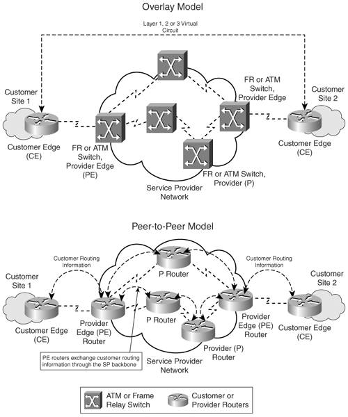
The peer-to-peer model was developed to overcome the drawbacks of the Overlay model and provide customers with optimal data transport via the SP backbone. Hence, the service provider would actively participate in customer routing. In the peer-to-peer model, routing information is exchanged between the customer routers and the service provider routers, and customer data is transported across the service provider's core, optimally. Customer routing information is carried between routers in the provider network (P and PE routers) and customer network (CE routers). The peer-to-peer model, consequently, does not require the creation of virtual circuits. As illustrated in Figure 3-1, the CE routers exchange routes with the connected PE routers in the SP domain. Customer routing information is propagated across the SP backbone between PE and P routers and identifies the optimal path from one customer site to another.
Separation of customer-specific routing information is achieved by implementing packet filters at the routers connecting to the customer network. Additionally, IP addressing for the customer is handled by the service provider. This process is also referred to as the shared PE peer-to-peer implementation. Figure 3-2 depicts the various implementations of the peer-to-peer model.
Figure 3-2. Peer-to-Peer Model Implementations
Controlled route distribution was another method of implementing the peer-to-peer model; routers in the core of the service provider's network contained network layer reachability information for all customers' networks. The PE routers (connecting customer network to provider network) in the provider network would contain only information pertaining to their connected customers. A dedicated PE router was required for each customer's site connecting to the provider network, and controlled route distribution would occur between P and PE routers in the SP backbone network. Only pertinent customer routes would be propagated to PE routers that were connected to sites belonging to a specific customer. BGP with communities was usually used in the SP backbone because it offered the most versatile route-filtering tools. This implementation is often referred to as the dedicated PE peer-to-peer model. This implementation, however, did not prove to be a viable operating business model due to the higher equipment costs that were incurred by the provider to maintain dedicated edge routers for customer sites connecting into the provider backbone. A need arose for deploying efficient VPN architectures that could implement a scalable peer-to-peer model.
MPLS Overview
- MPLS Overview
- Unicast IP Forwarding in Traditional IP Networks
- Overview of MPLS Forwarding
- MPLS Terminology
- MPLS Control and Data Plane Components
- MPLS Operation
- Special Outgoing Label Types
- Penultimate Hop Popping
- Frame-Mode MPLS
- Cell-Mode MPLS
Basic MPLS Configuration
- Basic MPLS Configuration
- Frame-Mode MPLS Configuration and Verification
- Cell-Mode MPLS over ATM Overview, Configuration, and Verification
- Command Reference
Basic MPLS VPN Overview and Configuration
- Basic MPLS VPN Overview and Configuration
- VPN Categories
- MPLS VPN Architecture and Terminology
- MPLS VPN Routing Model
- MPLS VPN Basic Configuration
- Outbound Route Filters
- Command Reference
PE-CE Routing Protocol-Static and RIP
- PE-CE Routing Protocol-Static and RIP
- Static PE-CE Routing Overview, Configuration, and Verification
- Static PE-CE Routing Command Reference
- RIPv2 PE-CE Routing Overview, Configuration, and Verification
- RIPv1 PE-CE Routing Configuration and Verification
- RIP PE-CE Routing Command Reference
PE-CE Routing Protocol-OSPF and EIGRP
- PE-CE Routing Protocol-OSPF and EIGRP
- OSPF PE-CE Routing Protocol Overview, Configuration and Verification
- EIGRP PE-CE Routing Protocol Overview, Configuration, and Verification
Implementing BGP in MPLS VPNs
- Implementing BGP in MPLS VPNs
- BGP PE-CE Routing Protocol Overview, Configuration, and Verification
- Implementing Route-Reflectors in MPLS VPN Networks
- Case Study-Hub and Spoke MPLS VPN Network Using BGP PE-CE Routing for Sites Using Unique AS Numbers
- Case Study-Hub and Spoke MPLS VPN Network with Sites Using Same AS Numbers
- Command Reference
Inter-Provider VPNs
- Inter-Provider VPNs
- Overview of Inter-Provider VPNs
- Option 1: Inter-Provider VPN Using Back-to-Back VRF Method
- Option 2: Inter-Provider VPNs Using ASBR-to-ASBR Approach
- Option 3: Multi-Hop MP-eBGP Between RR and eBGP Between ASBRs
- Option 4: Non-VPN Transit Provider
- Case Study-Inter-AS Implementing Route-Reflector and BGP Confederation in Provider Networks
- Case Study-Multi-Homed Inter-AS Provider Network
- Command Reference
Carrier Supporting Carriers
- Carrier Supporting Carriers
- Carrier Supporting Carriers Overview
- Deployment Scenarios with CSC Architecture
- CSC Architecture Benefits
- Command Reference
MPLS Traffic Engineering
- MPLS Traffic Engineering
- TE Basics
- MPLS TE Theory
- Constraint-Based Routing and Operation in MPLS TE
- Configuring MPLS TE
- Command Reference
Implementing VPNs with Layer 2 Tunneling Protocol Version 3
- Implementing VPNs with Layer 2 Tunneling Protocol Version 3
- L2TPv3 Overview
- Configuring L2TPv3 Tunnels for Layer 2 VPN
- Configuring L2TPv3 Static Tunnels
- Configuring L2TPv3 Dynamic Tunnels
- Implementing Layer 3 VPNs over L2TPv3 Tunnels
- Command Reference
Any Transport over MPLS (AToM)
- Any Transport over MPLS (AToM)
- Introduction to Layer 2 VPNs
- Implementing AToM for Like to Like Circuits
- L2 VPN-Any to Any Interworking
- Local Switching
- Command Reference
Virtual Private LAN Service (VPLS)
- Virtual Private LAN Service (VPLS)
- VPLS Overview
- VPLS Topology-Single PE or Direct Attachment
- Hierarchical VPLS-Distributed PE Architecture
- Command Reference
Implementing Quality of Service in MPLS Networks
- Implementing Quality of Service in MPLS Networks
- Introduction to QoS-Classification and Marking
- MPLS QoS Implementation
- MPLS QoS Operating Modes
- Modular QoS CLI: Configuration of QoS on Cisco Routers
- Configuration and Implementation of MPLS QoS in Uniform Mode and Short Pipe Mode Operation
- Implementing MPLS QoS for Layer 2 VPN Implementations
- Command Reference
MPLS Features and Case Studies
- MPLS Features and Case Studies
- Case Study 1: Implementing Multicast Support for MPLS VPNs
- Case Study 2: Implementing Multi-VRF CE, VRF Selection Using Source IP Address, VRF Selection Using Policy-Based Routing, NAT and HSRP Support in MPLS VPN, and Multicast VPN Support over Multi-VRF CE
- Case Study 3: Implementing Layer 2 VPNs over Inter-AS Topologies Using Layer 2 VPN Pseudo-Wire Switching
- Case Study 4: Implementing Layer 3 VPNs over Layer 2 VPN Topologies and Providing L2 VPN Redundancy
- Case Study 5: Implementing Dynamic Layer 3 VPNs Using mGRE Tunnels
- Case Study 6: Implementing Class-Based Tunnel Selection with MPLS Traffic Engineering
- Case Study 7: Implementing Hub and Spoke Topologies with OSPF
- Case Study 8: Implementing Hub and Spoke Topologies with EIGRP
- Case Study 9: Implementing VPLS Services with the GSR 12000 Series
- Case Study 10: BGP Site of Origin
- Command Reference
EAN: 2147483647
Pages: 130
