Deployment Scenarios with CSC Architecture
Three deployment scenarios are possible with CSC architecture:
- Customer carrier is not running MPLS inside its POP sites.
- Customer carrier is running MPLS inside its POP sites.
- Customer carrier is providing MPLS VPN services to user sites.
The following sections delve into each of the deployment scenarios in greater detail.
CSC Network – Customer Carrier Not Running MPLS
In this deployment model, devices in the customer carrier ISPX do not use MPLS and no IGP/LDP label exchange takes place inside the customer carrier network. MPLS is enabled only on the CE router (CSC-CE1-X-AS2 and CSC-CE2-X-AS2) interface peering with the PE router located in the backbone carrier network. The backbone carrier only has knowledge of the customer carrier's internal networks. To allow exchange of external networks belonging to the user sites (customer carrier clients like Customer A), an internal BGP (iBGP) session needs to be enabled on the customer edge (CE) routers located in the customer carrier network.
Figure 8-4 shows an example case study of this deployment model in which CSC-CE1-X-AS2 and CSC-CE2-X-AS2 are CE routers belonging to different ISPX POP sites, ISPX-POP1 and ISPX-POP2, in the customer carrier network.
Figure 8-4. Customer Carrier ISPX POP Sites Not Running MPLS
PE1-AS1 and PE2-AS1 are provider edge (PE) routers in the backbone carrier network. OSPF PE-CE routing is used between PE routers, PE1-AS1 and PE2-AS1, in the backbone carrier and CE routers, CSC-CE1-X-AS2 and CSC-CE2-X-AS2, in the customer carrier network. The ASBR routers, ASBR1-X-AS2 and ASBR2-X-AS2, provide services to user sites or Customer A sites, Site 1 and Site 2. MPLS is enabled on the PE-CE interfaces to facilitate label exchange so that an end-to-end label switched path (LSP) is formed between the CE routers, CSC-CE1-X-AS2 and CSC-CE2-X-AS2. MPLS is not enabled on interfaces connecting the CE and ASBR devices in the customer carrier network. An iBGP session is established between the CE routers, CSC-CE1-X-AS2 and CSC-CE2-X-AS2, to allow Customer A Sites 1 and 2 to exchange routing information. In this deployment model, because the ISPX-POP1 and ISPX-POP2 sites run BGP internally and need to have iBGP peering between, it is always practical to have route-reflector (RR) configured to avoid iBGP peering mesh. In this case, CSC-CE1-X-AS2 and CSC-CE2-X-AS2 act as RRs.
Control Plane Forwarding Operation – Customer Carrier Not Running MPLS
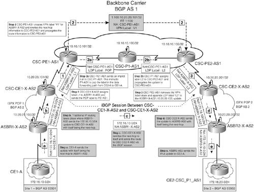
Figure 8-5 shows the control plane forwarding operation that takes place in the customer carrier not running the MPLS deployment model. Path a-b-c-d-e shows the control plane propagation for network 172.16.10.0/24, and path 1-2-2a-2b-3 shows the control plane propagation for 10.20.20.102/32, which is the next hop in the 172.16.10.0/24 update.
Figure 8-5. Control Plane Forwarding Operation – Customer Carrier ISPX POP Sites Not Running MPLS
Data Forwarding Operation – Customer Carrier Not Running MPLS
Figure 8-6 shows the data plane forwarding operation that takes place in the customer carrier not running the MPLS deployment model for a packet destined for network 172.16.10.0/24 originated by CE2-A.
Figure 8-6. Data Forwarding Operation – Customer Carrier ISPX POP Sites Not Running MPLS
Configuring the CSC Model – Customer Carrier Not Running MPLS
The steps to configure the CSC model in which the customer carrier is not running MPLS are as follows. Refer to the topology shown in Figure 8-4:
|
Step 1. |
Provision the MPLS VPN backbone carrier network – In this step, you configure the backbone carrier's PE and provider core routers, CSC-PE1-AS1, CSC-PE2-AS1, and CSC-P1-AS1, to provide MPLS VPN services to the carrier network. IS-IS is used as an IGP protocol in the backbone carrier's core. The PE-CE routing protocol is OSPF. Example 8-1 shows the configuration for CSC-PE1-AS1, CSC-PE2-AS1, and CSC-P1-AS1. Ensure that MPLS is enabled on the VRF enabled interfaces. Example 8-1. CSC-PE1-AS1, CSC-PE2-AS1, and CSC-P1-AS1 Configurations hostname CSC-PE1-AS1 ! ip cef ! ip vrf VRFX route-target export 1:100 route-target import 1:100 ! mpls ldp router-id Serial1/0 ! interface Loopback0 ip address 10.10.10.101 255.255.255.255 ! interface Serial0/0 ip address 10.10.10.1 255.255.255.252 ip router isis mpls ip ! interface Serial1/0 ip vrf forwarding VRFX ip address 10.12.12.1 255.255.255.252 mpls ip ! router ospf 2 vrf VRFX redistribute bgp 1 subnets network 10.12.12.0 0.0.0.255 area 0 ! router isis net 49.0001.0000.0000.0001.00 passive-interface Loopback0 ! router bgp 1 no synchronization neighbor 10.10.10.102 remote-as 1 neighbor 10.10.10.102 update-source Loopback0 no auto-summary ! address-family vpnv4 neighbor 10.10.10.102 activate neighbor 10.10.10.102 send-community extended exit-address-family ! address-family ipv4 vrf VRFX redistribute ospf 2 vrf VRFX match internal external 1 external 2 no auto-summary no synchronization exit-address-family __________________________________________________________________ hostname CSC-PE2-AS1 ! ip cef ! ip vrf VRFX route-target export 1:100 route-target import 1:100 ! mpls ldp router-id Serial1/0 ! interface Loopback0 ip address 10.10.10.102 255.255.255.255 ! interface Serial0/0 ip address 10.10.10.5 255.255.255.252 ip router isis mpls ip ! interface Serial1/0 ip vrf forwarding VRFX ip address 10.12.12.5 255.255.255.252 mpls ip ! router ospf 2 vrf VRFX redistribute bgp 1 subnets network 10.12.12.0 0.0.0.255 area 0 ! router isis net 49.0001.0000.0000.0003.00 passive-interface Loopback0 ! router bgp 1 no synchronization neighbor 10.10.10.101 remote-as 1 neighbor 10.10.10.101 update-source Loopback0 no auto-summary ! address-family vpnv4 neighbor 10.10.10.101 activate neighbor 10.10.10.101 send-community extended exit-address-family ! address-family ipv4 vrf VRFX redistribute ospf 2 vrf VRFX match internal external 1 external 2 no auto-summary no synchronization exit-address-family __________________________________________________________________ hostname CSC-P1-AS1 ! ip cef mpls ldp router-id Loopback0 ! interface Loopback0 ip address 10.10.10.100 255.255.255.255 ! interface Serial0/0 ip address 10.10.10.2 255.255.255.252 ip router isis mpls ip ! interface Serial1/0 ip address 10.10.10.6 255.255.255.252 ip router isis mpls ip ! router isis net 49.0001.0000.0000.0002.00 passive-interface Loopback0 |
|
Step 2. |
Configure the customer carrier network – In this step, CSC-CE1-X-AS2 and ASBR1-X-AS2 belonging to ISPX-POP1 and CSC-CE2-X-AS2 and ASBR2-X-AS2 belonging to ISPX-POP2 in the ISPX network are configured. In each POP site, OSPF is used as an IGP routing protocol. Example 8-2 shows the configuration for ISPX-POP1 and ISPX-POP2 devices. Example 8-2. ISPX-POP1 and ISPX-POP2 Device Configurations hostname CSC-CE1-X-AS2 ! ip cef ! interface Loopback0 ip address 10.20.20.101 255.255.255.255 ! interface Ethernet0/0 ip address 10.20.20.1 255.255.255.252 ! interface Serial1/0 ip address 10.12.12.2 255.255.255.252 mpls ip ! router ospf 2 network 10.12.12.0 0.0.0.255 area 0 network 10.20.20.0 0.0.0.255 area 0 ! router bgp 2 no synchronization bgp cluster-id 1 neighbor 10.20.20.102 remote-as 2 neighbor 10.20.20.102 update-source Loopback0 neighbor 10.20.20.102 route-reflector-client neighbor 10.20.20.102 next-hop-self neighbor 10.20.20.201 remote-as 2 neighbor 10.20.20.201 update-source Loopback0 neighbor 10.20.20.201 next-hop-self no auto-summary ________________________________________________________________ hostname CSC-CE2-X-AS2 ! ip cef ! interface Loopback0 ip address 10.20.20.201 255.255.255.255 ! interface Ethernet0/0 ip address 10.20.20.5 255.255.255.252 ! interface Serial1/0 ip address 10.12.12.6 255.255.255.252 mpls ip ! router ospf 2 network 10.12.12.0 0.0.0.255 area 0 network 10.20.20.0 0.0.0.255 area 0 ! router bgp 2 no synchronization bgp cluster-id 2 neighbor 10.20.20.101 remote-as 2 neighbor 10.20.20.101 update-source Loopback0 neighbor 10.20.20.101 next-hop-self neighbor 10.20.20.202 remote-as 2 neighbor 10.20.20.202 update-source Loopback0 neighbor 10.20.20.202 route-reflector-client neighbor 10.20.20.202 next-hop-self no auto-summary ________________________________________________________________ hostname ASBR1-X-AS2 ! interface Loopback0 ip address 10.20.20.102 255.255.255.255 ! interface Ethernet0/0 ip address 10.20.20.2 255.255.255.252 ! interface Serial1/0 ip address 172.16.1.1 255.255.255.252 ! router ospf 2 network 10.20.20.0 0.0.0.255 area 0 ! router bgp 2 no synchronization neighbor 10.20.20.101 remote-as 2 neighbor 10.20.20.101 update-source Loopback0 neighbor 10.20.20.101 next-hop-self neighbor 10.20.20.201 remote-as 2 neighbor 10.20.20.201 update-source Loopback0 neighbor 10.20.20.201 next-hop-self neighbor 172.16.1.2 remote-as 65001 no auto-summary ________________________________________________________________ hostname ASBR2-X-AS2 ! interface Loopback0 ip address 10.20.20.202 255.255.255.255 ! interface Ethernet0/0 ip address 10.20.20.6 255.255.255.252 ! interface Serial1/0 ip address 172.16.2.1 255.255.255.252 ! router ospf 2 network 10.20.20.0 0.0.0.255 area 0 ! router bgp 2 no synchronization neighbor 10.20.20.101 remote-as 2 neighbor 10.20.20.101 update-source Loopback0 neighbor 10.20.20.101 next-hop-self neighbor 10.20.20.201 remote-as 2 neighbor 10.20.20.201 update-source Loopback0 neighbor 10.20.20.201 next-hop-self neighbor 172.16.2.2 remote-as 65002 no auto-summary |
|
Step 3. |
Provision customer carrier's user sites – In this step, Customer A sites that are customer carrier ISPX user sites are configured. The customer carrier network runs eBGP with Customer A sites belonging to BGP AS 65001 and 65002, respectively. Example 8-3 shows the configuration for user devices CE1-A and CE2-A, respectively. Example 8-3. Customer A CE1-A and CE2-A Configurations hostname CE1-A ! interface Ethernet0/0 description Customer A Site 1 ip address 172.16.10.1 255.255.255.0 ! interface Serial1/0 ip address 172.16.1.2 255.255.255.252 ! router bgp 65001 no synchronization network 172.16.10.0 mask 255.255.255.0 neighbor 172.16.1.1 remote-as 2 no auto-summary ________________________________________________________________ hostname CE2-A ! interface Ethernet0/0 description Customer A Site 2 ip address 172.16.20.1 255.255.255.0 ! interface Serial1/0 ip address 172.16.2.2 255.255.255.252 ! router bgp 65002 no synchronization network 172.16.20.0 mask 255.255.255.0 neighbor 172.16.2.1 remote-as 2 no auto-summary |
Verify CSC Model – Customer Carrier Not Running MPLS
In this section, you verify
- Control plane operation
- Data forwarding operation
- Connectivity between the sites
The steps are as follows:
|
Step 1. |
Verify control plane operation – Figure 8-7 shows the control plane operation. Path a-b-c-d-e shows the control plane propagation for network 172.16.10.0/24, and path 1-2-2a-2b-3 shows the control plane propagation for 10.20.20.102/32, which is the next hop in the 172.16.10.0/24 update. Figure 8-7. Control Plane Forwarding 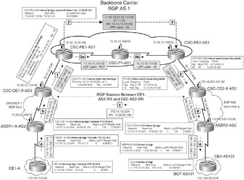
|
|
Step 2. |
Verify data forwarding – Figure 8-8 shows the data forwarding operation that takes place for a packet sourced from 172.16.20.1 to 172.16.10.1. Figure 8-8. Data Forwarding 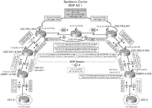
|
|
Step 3. |
Verify end-to-end connectivity via ping – Verify end-to-end connectivity between CE1-A and CE2-A by issuing a ping from CE1-A to network 172.16.20.1/24 on CE2-A and vice versa. Example 8-4 shows the result of the ping operation. Example 8-4. Verify End-to-End Connectivity CE1-A#ping 172.16.10.1 source 172.16.20.1 Type escape sequence to abort. Sending 5, 100-byte ICMP Echos to 172.16.10.1, timeout is 2 seconds: Packet sent with a source address of 172.16.20.1 !!!!! Success rate is 100 percent (5/5), round-trip min/avg/max = 140/140/140 ms |
CSC Network – Customer Carrier Running MPLS
The only difference between this CSC model and the one shown in the previous section is that in this deployment scenario, the customer carrier is running MPLS in its POP sites. Therefore, internal routes in the customer carrier's network will be assigned labels and label switched paths (LSPs) will be built inside each POP site.
Figure 8-9 shows the components in the CSC network in which the customer carrier is running MPLS. This figure is similar to the one shown in Figure 8-4 except that the iBGP session is now formed between ASBR1-X-AS2 and ASBR2-X-AS2. LDP is enabled on the ISPX-POP1 and ISPX-POP2 devices.
Figure 8-9. CSC Model with Customer Carrier Running MPLS
Control Plane Forwarding Operation – Customer Carrier Running MPLS
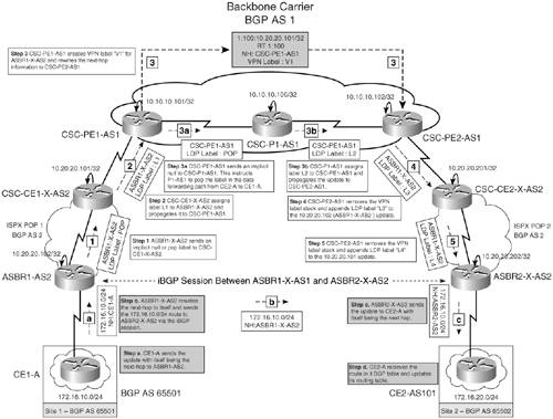
Figure 8-10 shows the control plane forwarding operation that takes place in the customer carrier running MPLS deployment model. Path a-b-c shows the control plane propagation for network 172.16.10.0/24, and path 1-2-3-3a-3b-4-5 shows the control plane propagation for 10.20.20.102/32, which is the next hop in the 172.16.10.0/24 update.
Figure 8-10. Control Plane Forwarding Operation – Customer Carrier ISPX POP Sites Running MPLS
Data Forwarding Operation – Customer Carrier Running MPLS
Figure 8-11 shows the data plane forwarding operation that takes place in the customer carrier running MPLS deployment model.
Figure 8-11. Data Forwarding Operation – Customer Carrier ISPX POP Sites Running MPLS
Configuring the CSC Model – Customer Carrier Running MPLS
The steps to configure the CSC model in which the customer carrier is running MPLS are as follows:
|
Step 1. |
Provision the MPLS VPN backbone carrier network – This step is similar to the one shown in the section "Configuring the CSC Model – Customer Carrier Not Running MPLS." |
|
Step 2. |
Configure the customer carrier network – In this step, configure CSC-CE1-X-AS2 and ASBR1-X-AS2 belonging to the ISPX-POP1 site, and CSC-CE2-X-AS2 and ASBR2-X-AS2 belonging to the ISPX-POP2 site in the ISPX network. Each of the POP sites is running OSPF as an IGP protocol. Example 8-5 shows the configuration for the POP1 and POP2 site devices. Example 8-5. ISPX-POP1 and ISPX-POP2 Device Configurations hostname CSC-CE1-X-AS2 ! ip cef ! interface Loopback0 ip address 10.20.20.101 255.255.255.255 ! interface Ethernet0/0 ip address 10.20.20.1 255.255.255.252 mpls ip ! interface Serial1/0 ip address 10.12.12.2 255.255.255.252 mpls ip ! router ospf 2 network 10.12.12.0 0.0.0.255 area 0 network 10.20.20.0 0.0.0.255 area 0 ! router bgp 2 no synchronization bgp cluster-id 1 bgp log-neighbor-changes neighbor 10.20.20.201 remote-as 2 neighbor 10.20.20.201 update-source Loopback0 neighbor 10.20.20.201 next-hop-self ________________________________________________________________ hostname CSC-CE2-X-AS2 ! ip cef ! interface Loopback0 ip address 10.20.20.201 255.255.255.255 ! interface Ethernet0/0 ip address 10.20.20.5 255.255.255.252 mpls ip ! interface Serial1/0 ip address 10.12.12.6 255.255.255.252 mpls ip ! router ospf 2 network 10.12.12.0 0.0.0.255 area 0 network 10.20.20.0 0.0.0.255 area 0 ! router bgp 2 no synchronization bgp cluster-id 2 bgp log-neighbor-changes neighbor 10.20.20.101 remote-as 2 neighbor 10.20.20.101 update-source Loopback0 neighbor 10.20.20.101 next-hop-self no auto-summary ________________________________________________________________ hostname ASBR1-X-AS2 ! ip cef ! interface Loopback0 ip address 10.20.20.102 255.255.255.255 ! interface Ethernet0/0 ip address 10.20.20.2 255.255.255.252 mpls ip ! interface Serial1/0 ip address 172.16.1.1 255.255.255.252 ! router ospf 2 network 10.20.20.0 0.0.0.255 area 0 ! router bgp 2 no synchronization neighbor 10.20.20.202 remote-as 2 neighbor 10.20.20.202 update-source Loopback0 neighbor 10.20.20.202 next-hop-self neighbor 172.16.1.2 remote-as 65001 no auto-summary ________________________________________________________________ hostname ASBR2-X-AS2 ! ip cef ! interface Loopback0 ip address 10.20.20.202 255.255.255.255 ! interface Ethernet0/0 ip address 10.20.20.6 255.255.255.252 mpls ip ! interface Serial1/0 ip address 172.16.2.1 255.255.255.252 ! router ospf 2 network 10.20.20.0 0.0.0.255 area 0 ! router bgp 2 no synchronization neighbor 10.20.20.102 remote-as 2 neighbor 10.20.20.102 update-source Loopback0 neighbor 10.20.20.102 next-hop-self neighbor 172.16.2.2 remote-as 65002 no auto-summary |
|
Step 3. |
Provision customer carrier's user sites – This step is similar to Step 3 shown in the section "Configuring the CSC Model – Customer Carrier Not Running MPLS." Refer to Example 8-3 for configurations. |
Verify CSC Model – Customer Carrier Running MPLS
In this section, you verify
- Control plane operation
- Data forwarding operation
- Connectivity between the sites
The steps are as follows:
|
Step 1. |
Verify control plane operation – Figure 8-12 shows the control plane traffic for the CSC model with customer carrier running MPLS. Path a-b-c shows the control plane propagation for network 172.16.10.0/24, and path 1-2-2a-2b-3-4-5 shows the control plane propagation for 10.20.20.102/32, which is the next hop in the 172.16.10.0/24 update. Figure 8-12. Control Plane Forwarding 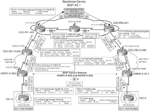
|
|
Step 2. |
Verify data forwarding operation – Figure 8-13 shows the data forwarding that takes place for a packet sourced from 172.16.20.1 to 172.16.10.1. Figure 8-13. Data Plane Forwarding 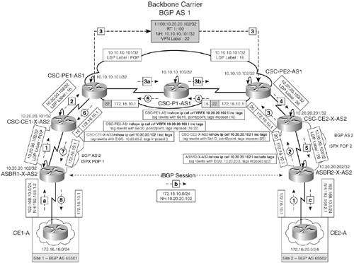
|
|
Step 3. |
Verify end-to-end connectivity via ping – Verify end-to-end connectivity between CE1-A and CE2-A by issuing a ping from CE2-A to network 172.16.10.1/24 on CE1-A. Example 8-6 shows the result of the ping operation. Example 8-6. Verify End-to-End Connectivity CE2-A#ping 172.16.10.1 source 172.16.20.1 Type escape sequence to abort. Sending 5, 100-byte ICMP Echos to 172.16.10.1, timeout is 2 seconds: Packet sent with a source address of 172.16.20.1 !!!!! Success rate is 100 percent (5/5), round-trip min/avg/max = 140/140/140 ms |
CSC Network – Customer Carrier Providing MPLS VPN Service
In this deployment scenario, the customer carrier provides MPLS VPN services to its clients. In order to provide MPLS VPN services, an MP-iBGP session is required between the customer carrier routers located at different POP sites to transport VPNv4 information. The VPNv4 label exchange is transparent to the backbone carrier. The backbone carrier holds only the internal routes of the customer carrier and not that of the customer carrier's clients. Figure 8-14 shows a CSC network in which the customer carrier ISPX provides MPLS VPN services to Customer A sites, Site 1 and Site 2, belonging to BGP AS 65501 and 65502, respectively. The sites belong to the same VPN.
Figure 8-14. Customer Carrier Providing MPLS VPN Services
The customer carrier's ASBRs, ASBR1-X-AS2 and ASBR2-X-AS2, hold the VRF routing information for its clients and use MP-iBGP sessions between the ASBRs to transport VPNv4 information between the two sites. Because the backbone carrier is providing MPLS VPN service to the customer carrier, which in turn is also providing MPLS VPN service to Customer A sites, this type of deployment scenario is also known as hierarchical VPN.
Control Plane Forwarding Operation – Customer Carrier Providing MPLS VPN Service
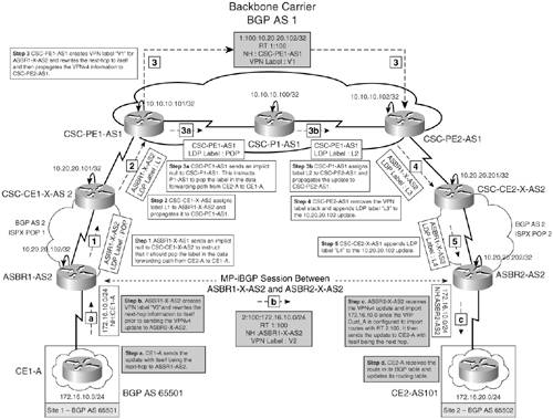
Figure 8-15 shows the control plane forwarding operation that takes place in the customer carrier providing MPLS VPN services model. Path a-b-c shows the control plane propagation for network 172.16.10.0/24, and path 1-2-3-3a-3b-4-5 shows the control plane propagation for 10.20.20.102/32, which is the next hop in the 172.16.10.0/24 update.
Figure 8-15. Control Plane Forwarding Operation – Customer Carrier ISPX POP Sites Providing MPLS VPN Services
Data Forwarding Operation – Customer Carrier Providing MPLS VPN Service
Figure 8-16 shows the data forwarding operation that takes place in the customer carrier providing MPLS VPN services model.
Figure 8-16. Data Forwarding Operation – Customer Carrier ISPX POP Sites Providing MPLS VPN Services
Configuring the CSC Model – Customer Carrier Providing MPLS VPN Service
The steps to configure the CSC model in which the customer carrier is providing MPLS VPN services are as follows. Refer to the topology shown in Figure 8-14:
|
Step 1. |
Provision the MPLS VPN backbone carrier network – This step is similar to the one shown in the section "Configuring the CSC Model – Customer Carrier Not Running MPLS." |
|
Step 2. |
Configure the customer carrier network – In this step, you configure the MP-iBGP session between ASBR1-X-AS2 and ASBR2-X-AS2 to transport VPNv4 belonging to the ISPX-POP2 site in the ISPX network. Each of the POP sites is running OSPF as the IGP routing protocol. Example 8-7 shows the configuration for POP1 and POP2 site devices. Refer to Example 8-5 for configurations related to CSC-CE1-X-AS2 and CSC-CE2-X-AS2. Example 8-7. ASBR Configurations hostname ASBR1-X-AS2 ! ip cef ! ip vrf Cust_A rd 2:100 route-target export 2:100 route-target import 2:100 ! interface Loopback0 ip address 10.20.20.102 255.255.255.255 ! interface Ethernet0/0 ip address 10.20.20.2 255.255.255.252 mpls ip ! interface Serial1/0 ip vrf forwarding Cust_A ip address 172.16.1.1 255.255.255.252 ! router ospf 2 network 10.20.20.0 0.0.0.255 area 0 ! router bgp 2 no synchronization neighbor 10.20.20.202 remote-as 2 neighbor 10.20.20.202 update-source Loopback0 neighbor 10.20.20.202 next-hop-self no auto-summary ! address-family vpnv4 neighbor 10.20.20.202 activate neighbor 10.20.20.202 send-community extended exit-address-family ! address-family ipv4 vrf Cust_A neighbor 172.16.1.2 remote-as 65001 neighbor 172.16.1.2 activate no auto-summary no synchronization exit-address-family ________________________________________________________________ hostname ASBR2-X-AS2 ! ip cef ! ip vrf Cust_A rd 2:100 route-target export 2:100 route-target import 2:100 ! interface Loopback0 ip address 10.20.20.202 255.255.255.255 ! interface Ethernet0/0 ip address 10.20.20.6 255.255.255.252 mpls ip ! interface Serial1/0 ip vrf forwarding Cust_A ip address 172.16.2.1 255.255.255.252 ! router ospf 2 network 10.20.20.0 0.0.0.255 area 0 ! router bgp 2 no synchronization neighbor 10.20.20.102 remote-as 2 neighbor 10.20.20.102 update-source Loopback0 neighbor 10.20.20.102 next-hop-self no auto-summary ! address-family vpnv4 neighbor 10.20.20.102 activate neighbor 10.20.20.102 send-community extended exit-address-family ! address-family ipv4 vrf Cust_A neighbor 172.16.2.2 remote-as 65002 neighbor 172.16.2.2 activate no auto-summary no synchronization exit-address-family |
|
Step 3. |
Provision customer carrier's user sites – This step is similar to Step 3 in the section "Configuring the CSC Model – Customer Carrier Not Running MPLS." Refer to Example 8-3 for configurations related to CE1-A and CE2-A. |
Verify CSC Model – Customer Carrier Providing MPLS VPN Service
In this section, you verify
- Control plane operation
- Data forwarding operation
- Connectivity between the sites
The steps are as follows:
|
Step 1. |
Verify control plane operation – Figure 8-17 shows the control plane traffic for the CSC model with the customer carrier providing MPLS VPN services. Path a-b-c shows the control plane propagation for network 172.16.10.0/24, and path 1-2-2a-2b-3-4-5 shows the control plane propagation for 10.20.20.102/32, which is the next hop in the 172.16.10.0/24 update. Figure 8-17. Control Plane Forwarding 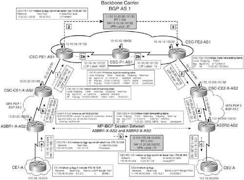
|
|
Step 2. |
Verify data forwarding – Figure 8-18 shows the data forwarding that takes place for a packet sourced from 172.16.20.1 to 172.16.10.1. Figure 8-18. Data Forwarding 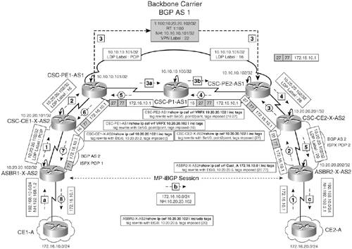
|
|
Step 3. |
Verify end-to-end connectivity via ping – Verify end-to-end connectivity between CE1-A and CE2-A by issuing a ping from CE1-A to 172.16.20.1 belonging to network 172.16.20.0/24 on CE2-A and vice versa. Example 8-8 shows the result of the ping operation. Example 8-8. Verify End-to-End Connectivity CE2-A#ping 172.16.10.1 source 172.16.20.1 Type escape sequence to abort. Sending 5, 100-byte ICMP Echos to 172.16.10.1, timeout is 2 seconds: Packet sent with a source address of 172.16.20.1 !!!!! Success rate is 100 percent (5/5), round-trip min/avg/max = 140/140/140 ms |
MPLS Overview
- MPLS Overview
- Unicast IP Forwarding in Traditional IP Networks
- Overview of MPLS Forwarding
- MPLS Terminology
- MPLS Control and Data Plane Components
- MPLS Operation
- Special Outgoing Label Types
- Penultimate Hop Popping
- Frame-Mode MPLS
- Cell-Mode MPLS
Basic MPLS Configuration
- Basic MPLS Configuration
- Frame-Mode MPLS Configuration and Verification
- Cell-Mode MPLS over ATM Overview, Configuration, and Verification
- Command Reference
Basic MPLS VPN Overview and Configuration
- Basic MPLS VPN Overview and Configuration
- VPN Categories
- MPLS VPN Architecture and Terminology
- MPLS VPN Routing Model
- MPLS VPN Basic Configuration
- Outbound Route Filters
- Command Reference
PE-CE Routing Protocol-Static and RIP
- PE-CE Routing Protocol-Static and RIP
- Static PE-CE Routing Overview, Configuration, and Verification
- Static PE-CE Routing Command Reference
- RIPv2 PE-CE Routing Overview, Configuration, and Verification
- RIPv1 PE-CE Routing Configuration and Verification
- RIP PE-CE Routing Command Reference
PE-CE Routing Protocol-OSPF and EIGRP
- PE-CE Routing Protocol-OSPF and EIGRP
- OSPF PE-CE Routing Protocol Overview, Configuration and Verification
- EIGRP PE-CE Routing Protocol Overview, Configuration, and Verification
Implementing BGP in MPLS VPNs
- Implementing BGP in MPLS VPNs
- BGP PE-CE Routing Protocol Overview, Configuration, and Verification
- Implementing Route-Reflectors in MPLS VPN Networks
- Case Study-Hub and Spoke MPLS VPN Network Using BGP PE-CE Routing for Sites Using Unique AS Numbers
- Case Study-Hub and Spoke MPLS VPN Network with Sites Using Same AS Numbers
- Command Reference
Inter-Provider VPNs
- Inter-Provider VPNs
- Overview of Inter-Provider VPNs
- Option 1: Inter-Provider VPN Using Back-to-Back VRF Method
- Option 2: Inter-Provider VPNs Using ASBR-to-ASBR Approach
- Option 3: Multi-Hop MP-eBGP Between RR and eBGP Between ASBRs
- Option 4: Non-VPN Transit Provider
- Case Study-Inter-AS Implementing Route-Reflector and BGP Confederation in Provider Networks
- Case Study-Multi-Homed Inter-AS Provider Network
- Command Reference
Carrier Supporting Carriers
- Carrier Supporting Carriers
- Carrier Supporting Carriers Overview
- Deployment Scenarios with CSC Architecture
- CSC Architecture Benefits
- Command Reference
MPLS Traffic Engineering
- MPLS Traffic Engineering
- TE Basics
- MPLS TE Theory
- Constraint-Based Routing and Operation in MPLS TE
- Configuring MPLS TE
- Command Reference
Implementing VPNs with Layer 2 Tunneling Protocol Version 3
- Implementing VPNs with Layer 2 Tunneling Protocol Version 3
- L2TPv3 Overview
- Configuring L2TPv3 Tunnels for Layer 2 VPN
- Configuring L2TPv3 Static Tunnels
- Configuring L2TPv3 Dynamic Tunnels
- Implementing Layer 3 VPNs over L2TPv3 Tunnels
- Command Reference
Any Transport over MPLS (AToM)
- Any Transport over MPLS (AToM)
- Introduction to Layer 2 VPNs
- Implementing AToM for Like to Like Circuits
- L2 VPN-Any to Any Interworking
- Local Switching
- Command Reference
Virtual Private LAN Service (VPLS)
- Virtual Private LAN Service (VPLS)
- VPLS Overview
- VPLS Topology-Single PE or Direct Attachment
- Hierarchical VPLS-Distributed PE Architecture
- Command Reference
Implementing Quality of Service in MPLS Networks
- Implementing Quality of Service in MPLS Networks
- Introduction to QoS-Classification and Marking
- MPLS QoS Implementation
- MPLS QoS Operating Modes
- Modular QoS CLI: Configuration of QoS on Cisco Routers
- Configuration and Implementation of MPLS QoS in Uniform Mode and Short Pipe Mode Operation
- Implementing MPLS QoS for Layer 2 VPN Implementations
- Command Reference
MPLS Features and Case Studies
- MPLS Features and Case Studies
- Case Study 1: Implementing Multicast Support for MPLS VPNs
- Case Study 2: Implementing Multi-VRF CE, VRF Selection Using Source IP Address, VRF Selection Using Policy-Based Routing, NAT and HSRP Support in MPLS VPN, and Multicast VPN Support over Multi-VRF CE
- Case Study 3: Implementing Layer 2 VPNs over Inter-AS Topologies Using Layer 2 VPN Pseudo-Wire Switching
- Case Study 4: Implementing Layer 3 VPNs over Layer 2 VPN Topologies and Providing L2 VPN Redundancy
- Case Study 5: Implementing Dynamic Layer 3 VPNs Using mGRE Tunnels
- Case Study 6: Implementing Class-Based Tunnel Selection with MPLS Traffic Engineering
- Case Study 7: Implementing Hub and Spoke Topologies with OSPF
- Case Study 8: Implementing Hub and Spoke Topologies with EIGRP
- Case Study 9: Implementing VPLS Services with the GSR 12000 Series
- Case Study 10: BGP Site of Origin
- Command Reference
EAN: 2147483647
Pages: 130
