EIGRP PE-CE Routing Protocol Overview, Configuration, and Verification
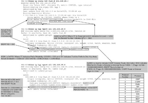
EIGRP PE-CE routing protocol is used by service providers for customers who use EIGRP as their IGP routing protocol and, hence, prefer to use EIGRP to exchange routing information between the customer sites across an MPLS VPN backbone. In an MPLS VPN environment, to achieve this, the original EIGRP metrics must be carried inside MP-BGP updates. This is achieved by using BGP extended community attributes to carry and preserve EIGRP metrics when crossing the MP-iBGP domain. These communities define the intrinsic characteristics associated with EIGRP, such as the AS number or EIGRP cost metric like bandwidth, delay, load, reliability, and MTU. As shown in Table 5-2, six extended BGP communities have been defined to carry the EIGRP routes across the MPLS backbone via MP-BGP.
|
EIGRP Attribute |
Type |
Usage |
Value |
|---|---|---|---|
|
General |
0x8800 |
EIGRP General Route Information |
Route Flag and Tag |
|
Metric |
0x8801 |
EIGRP Route Metric Information and AS |
AS and Delay |
|
0x8802 |
EIGRP Route Metric Information |
Reliability, Next Hop, and Bandwidth |
|
|
0x8803 |
EIGRP Route Metric Information |
Reserve, Load, and Maximum Transmission Unit (MTU) |
|
|
0x8804 |
EIGRP External Route Information |
Remote AS and Remote ID |
|
|
External |
0x8805 |
EIGRP External Route Information |
Remote Protocol and Remote Metric |
Figure 5-21 gives the details on the extended BGP community attribute that are attached to sample routes 192.168.20.0 and 192.168.99.0.
Figure 5-21. BGP Extended Communities Explained
EIGRP Route Propagation
Route propagation in MPLS VPN networks using EIGRP PE-CE routing is based on EIGRP AS configured on the PE routers. In an MPLS VPN environment, EIGRP AS can be the same on all PE routers or different on all PE routers.
Route Propagation When EIGRP AS Is Same on All PE Routers
Figure 5-22 shows an MPLS VPN provider network providing MPLS VPN services to Customer A. PE1-AS1 and PE2-AS1 are configured for EIGRP AS 101.
Figure 5-22. Route Propagation When EIGRP AS Is Same on PE Routers

The following sequence takes place when CE2-A is sending 172.16.20.0 and 209.165.201.0 to CE1-A:
- CE2-A redistributes OSPF network 209.165.127.0/27 as an EIGRP external route (D EX) and 172.16.20.0/24 as an internal route (D) to PE2-AS1.
- Figure 5-22 shows that the VRF Cust_A routing table on PE2-AS1 receives 172.16.20.0/24 as internal route with EIGRP metric 2195456 and 209.165.127.0/27 as an external route with EIGRP metric 3097600.
- The EIGRP metrics for 172.16.20.0 and 209.165.127.0 are copied into extended BGP attributes as BGP MEDs, and extended communities containing EIGRP information such as AS, MTU, route type, and so on are attached when EIGRP routes are redistributed into MP-BGP. The routes 172.16.20.0 and 209.165.127.0 are then propagated to PE1-AS1 via MP-iBGP session.
- PE1-AS1 receives the BGP VPNv4 routes 172.16.20.0/24 and 209.165.127.0/27 from PE2-AS1. As shown in Figure 5-22, the EIGRP metric for the routes are not altered and remain the same when propagated though the MP-BGP backbone.
- PE2-AS1 checks the attributes received in the route, and, if route type is internal (if the MSB bit in the 0x8800 BGP extended community attribute is set) and the source AS matches what is configured on the receiving PE router, the route is advertised as EIGRP internal route. If the route type is external (MSB bit in 0x8800 is not set), the route is advertised to the CE as an external EIGRP route.
PE1-AS1, therefore, uses the extended community attribute information to reconstruct the original EIGRP routing update when redistributing from MP-BGP into EIGRP. This redistribution behavior takes place only if the PE2-AS1 EIGRP AS number is equal to the PE1-AS1, PE's EIGRP AS number. The PE routers act as EIGRP query boundaries. In this case, the route type for 172.16.20.0 is internal and source AS 101 matches on the receiving router PE1-AS1. Therefore, 172.16.20.0/24 is propagated as an EIGRP internal route to CE1-A. The route type for 209.165.127.0/27 is external and, therefore, is propagated to CE1-A as an external route.
- As shown in the figure, CE1-A receives the 172.16.20.0 as an internal route and 209.165.127.0 as an external route.
Route Propagation When EIGRP AS Is Different on All PE Routers
If the two EIGRP AS numbers are different, the normal redistribution rules apply; that is, external EIGRP routes are created when the customer routes are redistributed into EIGRP from MP-BGP updates. Figure 5-23 shows an MPLS VPN provider network using different EIGRP AS on PE routers PE1-AS1 and PE2-AS1. Because the MPLS backbone is transparent to the CE routing protocol, no EIGRP adjacency is formed or EIGRP updates and queries sent across the PE routers.
Figure 5-23. Route Propagation When EIGRP AS Is Different on PE Routers
The sequence shown in 1 through 4 in the section "Route Propagation When EIGRP AS Is Same on All PE Routers" remains the same except for networks 192.168.99.0 and 192.168.20.0 and the metric:
- PE2-AS1 checks the attributes received in the route, and, if the route type is internal and the source AS does not match or if the route type is external, the route is advertised to the CE as an external EIGRP route. The route will not use the extended community information because it did not originate from the same AS. Route type for 192.168.20.0 is internal and source AS, which is 202, does not match the configured AS on PE1-AS1 (201). Therefore, PE1-AS1 propagates that as an external route to CE1-A. The route type for 192.168.99.0 is external, and, therefore, both routes are propagated to CE1-A as external routes.
- As illustrated in Figure 5-23, CE1-A receives 192.168.20.0/24 and 192.168.99.0/24 as external routes.
Configuration Flowchart for EIGRP PE-CE Routing
Figure 5-24 shows the configuration flowchart to configure EIGRP PE-CE routing.
Figure 5-24. EIGRP PE-CE Routing Configuration Flowchart
The following are key points to be noted from the configuration flowchart:
- Address family configuration mode is used to configure the EIGRP AS for a given VRF.
- To allow a single EIGRP process to be used, the EIGRP AS has to be configured within the EIGRP address family configuration mode.
Other EIGRP configuration steps are the same as with normal EIGRP configuration. The default metric should be specified for the redistribution of non-EIGRP routes.
Configuration Scenario 1: Basic EIGRP PE-CE Routing Configuration
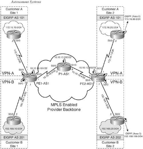
The objective of this configuration scenario is to demonstrate EIGRP PE-CE configuration and EIGRP route propagation when PE routers belong to the same EIGRP AS for a VRF and when they are in different EIGRP AS for a VRF. Figure 5-25 shows an MPLS VPN service provider providing MPLS VPN services to Customer A and Customer B sites:
- Customer A Network – Customer A has CE1-A and CE2-A located in the same VPN, VPN-A. They are part of EIGRP AS 101. EIGRP AS 101 is configured for VRF Cust_A on PE1-AS1 and PE2-AS1.
- Customer B Network – Customer B has CE1-B and CE2-B located in the same VPN, VPN-B. CE1-B and CE2-B belong to different EIGRP AS, 201 and 202. PE1-AS1 and PE2-AS1 have EIGRP AS 201 and 202 configured for VRF Cust_B, respectively.
Figure 5-25. MPLS VPN Network Implementing EIGRP PE-CE Routing with Same and Different EIGRP
The steps to configure EIGRP PE-CE routing are as follows:
|
Step 1. |
Enable the global EIGRP routing process – Enable the global EIGRP routing process on PE routers, PE1-AS1 and PE2-AS1. |
|
Step 2. |
Define per VRF EIGRP routing context and parameters – In this step, define - Per VRF EIGRP routing context for VRF Cust_A and Cust_B under the EIGRP routing process defined in Step 1. This number can be the same or different from the EIGRP AS number configured under the routing context. - Configure the networks that need to be enabled for EIGRP using the network command. - Ensure that no auto-summary is configured; otherwise, EIGRP summarizes networks at their classful boundaries. The command no auto-summary may be enabled by default depending on the version of IOS in use. - To allow a single global EIGRP process to be used, the EIGRP AS has to be configured within the EIGRP address family configuration mode. This is accomplished by configuring autonomous-system as-number in address-family mode. This allows the same EIGRP AS number to be used in multiple VRFs. Steps 1 and 2 for VRF Cust_B are shown in Example 5-33.Example 5-33. Step 1: Enable EIGRP Routing Process and Step 2: Define VRF Routing Context PE1-AS1(config)#router eigrp 1 PE1-AS1(config-router)#address-family ipv4 vrf Cust_B PE1-AS1(config-router-af)# network 172.16.0.0 PE1-AS1(config-router-af)# no auto-summary PE1-AS1(config-router-af)# autonomous-system 201 PE1-AS1(config-router-af)# exit-address-family ________________________________________________________________ PE2-AS1(config)#router eigrp 1 PE2-AS1(config-router)# address-family ipv4 vrf Cust_B PE2-AS1(config-router-af)# network 172.16.0.0 PE2-AS1(config-router-af)# no auto-summary PE2-AS1(config-router-af)# autonomous-system 202 PE2-AS1(config-router-af)# exit-address-family |
|
Step 3. |
Redistribute BGP VPNv4 routes in EIGRP – In this step, you redistribute the BGP VPNv4 routes from the remote PE routers in EIGRP. Example 5-34 shows the configuration to redistribute BGP routes in EIGRP for PE1-AS1 for VRF Cust_A. Repeat the steps for Customer A VRF Cust_A on PE2-AS1 and Customer B VRF Cust_B on PE1-AS1 and PE2-AS1. Example 5-34. Redistribute BGP VPNv4 Routes in EIGRP PE1-AS1(config)#router eigrp 1 PE1-AS1(config-router)# address-family ipv4 vrf Cust_A PE1-AS1(config-router-af)# redistribute bgp 1 metric 1000 100 255 1 1500 |
|
Step 4. |
Redistribute EIGRP routes in BGP – In this step, the EIGRP routes received from the local CE router are redistributed in BGP on the PE router. Example 5-35 shows the procedure to configure redistribution of EIGRP routes in BGP on PE1-AS1. Repeat the same steps on PE2-AS1 for VRF Cust_A. Similarly, redistribute EIGRP routes in BGP on PE1-AS1 and PE2-AS1 for VRF Cust_B. Use EIGRP AS 201 and 202 on PE1-AS1 and PE2-AS1 for VRF Cust_B. Example 5-35. Redistribute EIGRP Routes in BGP PE1-AS1(config)#router bgp 1 PE1-AS1(config-router)#address-family ipv4 vrf Cust_A PE1-AS1(config-router-af)#redistribute eigrp 101 ________________________________________________________________ PE2-AS1(config)#router bgp 1 PE2-AS1(config-router)# address-family ipv4 vrf Cust_A PE2-AS1(config-router-af)# redistribute eigrp 101 |
Final Configuration for PE Routers
Example 5-36 shows the final configuration for the PE routers.
Example 5-36. Final Configuration for the PE Routers
hostname PE1-AS1

!

ip cef

!

ip vrf Cust_A

 rd 1:100

 route-target export 1:100

 route-target import 1:100

!

ip vrf Cust_B

 rd 1:200

 route-target export 1:200

 route-target import 1:200

!

interface Loopback0

 ip address 10.10.10.101 255.255.255.255

!

interface Serial0/0

 description connected to P1-AS1

 ip address 10.10.10.1 255.255.255.252

 mpls ip

!

interface Serial1/0

 description connected to CE1-A

 ip vrf forwarding Cust_A

 ip address 172.16.1.1 255.255.255.252

!

interface Serial2/0

 description connected to CE1-B

 ip vrf forwarding Cust_B

 ip address 192.168.1.1 255.255.255.252

!

router eigrp 1

 auto-summary

 !

 address-family ipv4 vrf Cust_B

 redistribute bgp 1 metric 1000 100 255 1 1500

 network 192.168.1.0

 no auto-summary

 autonomous-system 201

 exit-address-family

 !

 address-family ipv4 vrf Cust_A

 redistribute bgp 1 metric 1000 100 255 1 1500

 network 172.16.0.0

 no auto-summary autonomous-system 101

 exit-address-family

!

router ospf 1

 router-id 10.10.10.101

 network 10.0.0.0 0.255.255.255 area 0

!

router bgp 1

 no synchronization

 neighbor 10.10.10.102 remote-as 1

 neighbor 10.10.10.102 update-source Loopback0

 no auto-summary

 !

 address-family vpnv4

 neighbor 10.10.10.102 activate

 neighbor 10.10.10.102 send-community extended

 exit-address-family

 !

 address-family ipv4 vrf Cust_B

 redistribute eigrp 201

 no auto-summary

 no synchronization

 exit-address-family

 !

 address-family ipv4 vrf Cust_A

 redistribute eigrp 101

 no auto-summary

 no synchronization

 exit-address-family

_________________________________________________________________________

hostname PE2-AS1

!

ip cef

!

ip vrf Cust_A

 rd 1:100

 route-target export 1:100

 route-target import 1:100

!

ip vrf Cust_B

 rd 1:200

 route-target export 1:200

 route-target import 1:200

!

interface Loopback0

 ip address 10.10.10.102 255.255.255.255

!

interface Serial0/0

 description connected to P1-AS1

 ip address 10.10.10.5 255.255.255.252

 mpls ip

!

interface Serial1/0

 description connected to CE2-A

 ip vrf forwarding Cust_A

 ip address 172.16.2.1 255.255.255.252

!

interface Serial2/0

 description connected to CE2-B

 ip vrf forwarding Cust_B

 ip address 192.168.2.1 255.255.255.252

!

router eigrp 1

 auto-summary

 !

 address-family ipv4 vrf Cust_B

 redistribute bgp 1 metric 1000 100 255 1 1500

 network 192.168.2.0

 no auto-summary

 autonomous-system 202

 exit-address-family

 !

 address-family ipv4 vrf Cust_A

 redistribute bgp 1 metric 1000 100 255 1 1500

 network 172.16.0.0

 no auto-summary

 autonomous-system 101

 exit-address-family

!

router ospf 1

 router-id 10.10.10.102

 network 10.0.0.0 0.255.255.255 area 0

!

router bgp 1

 no synchronization

 neighbor 10.10.10.101 remote-as 1

 neighbor 10.10.10.101 update-source Loopback0

 no auto-summary

 !

 address-family vpnv4

 neighbor 10.10.10.101 activate

 neighbor 10.10.10.101 send-community extended

 exit-address-family

 !

 address-family ipv4 vrf Cust_B

 redistribute eigrp 202

 no auto-summary

 no synchronization

 exit-address-family

 !

 address-family ipv4 vrf Cust_A

 redistribute eigrp 101

 no auto-summary

 no synchronization

 exit-address-family
Final Configuration for CE Routers
Example 5-37 shows the final configurations for the CE routers for Customer A (CE1-A and CE2-A) and Customer B (CE1-B and CE2-B).
Example 5-37. Final Configurations for CE1-A, CE2-A, CE1-B, and CE2-B
hostname CE1-A

!

interface Ethernet0/0

 description VPN-A Site 1 network

 ip address 172.16.10.1 255.255.255.0

!

interface Serial1/0

 description connected to PE1-AS1

 ip address 172.16.1.2 255.255.255.252

!

router eigrp 101

 network 172.16.0.0

 no auto-summary

_________________________________________________________________________

hostname CE2-A

!

interface Ethernet0/0

 description VPN-A Site 2 network

 ip address 172.16.20.1 255.255.255.0

!

interface Serial1/0

 description connected to PE2-AS1

 ip address 172.16.2.2 255.255.255.252

!

router eigrp 101

 network 172.16.0.0

 no auto-summary

_________________________________________________________________________

hostname CE1-B

!

interface Ethernet0/0

 description VPN-B Site1 network

 ip address 192.168.10.1 255.255.255.0

!

interface Serial1/0

 description connected to PE1-AS1

 ip address 192.168.1.2 255.255.255.252

!

router eigrp 201

 network 192.168.1.0

 network 192.168.10.0

 no auto-summary

_________________________________________________________________________

hostname CE2-B

!

interface Ethernet0/0

 description VPN-B Site2 network

 ip address 192.168.20.1 255.255.255.0

!

interface Serial1/0

 description connected to PE2-AS1

 ip address 192.168.2.2 255.255.255.252

!

router eigrp 202

 network 192.168.2.0

 network 192.168.20.0

 no auto-summary
Verify Basic EIGRP PE-CE Routing
The steps to verify EIGRP PE-CE routing are as follows:
|
Step 1. |
Verify EIGRP neighbor relationship – Example 5-38 shows the output on the PE1-AS1 and PE2-AS1. Example 5-38. Verify EIGRP Neighbor Relationship PE1-AS1#show ip eigrp vrf Cust_A neighbors IP-EIGRP neighbors for process 101 H Address Interface Hold Uptime SRTT RTO Q Seq Type (sec) (ms) Cnt Num 0 172.16.1.2 Se1/0 14 00:38:47 68 408 0 3 __________________________________________________________________________ PE1-AS1#show ip eigrp vrf Cust_B neighbors IP-EIGRP neighbors for process 201 H Address Interface Hold Uptime SRTT RTO Q Seq Type (sec) (ms) Cnt Num 0 192.168.1.2 Se2/0 11 00:38:54 81 486 0 4 |
|
Step 2. |
Verify EIGRP route propagation for Cust_B – Use the following sequence of steps to verify route propagation for Cust_B network 192.168.20.0 and 182.168.99.0. Example 5-39. Cust_B Routing Table on PE2-AS1 PE2-AS1#show ip route vrf Cust_B eigrp D EX 192.168.99.0/24 [170/3097600] via 192.168.2.2, 00:14:20, Serial2/0 D 192.168.20.0/24 [90/1787392] via 192.168.2.2, 00:14:20, Serial2/0 The EIGRP metric for 192.168.20.0 is copied into these attributes when the EIGRP route is redistributed into MP-BGP, as shown in Example 5-40. The command show ip bgp vpnv4 all 192.168.20.0 shows the extended BGP attributes that are attached to the route. Example 5-40. BGP VPNv4 Information for 192.168.20.0 on PE2-AS1 PE2-AS1#show ip bgp vpnv4 vrf Cust_B 192.168.20.0 BGP routing table entry for 1:200:192.168.20.0/24, version 20 Paths: (1 available, best #1, table Cust_B) Advertised to update-groups: 1 Local 192.168.2.2 (via Cust_B) from 0.0.0.0 (10.10.10.102) Origin incomplete, metric 1787392, localpref 100, weight 32768, valid, sourced, best Extended Community: RT:1:200 Cost:pre-bestpath:128:1787392 (default-2145696255) 0x8800:32768:0 0x8801:202:537600 0x8802:65281:1249792 0x8803:65281:1500, mpls labels in/out 23/nolabel PE1-AS1 redistributing back from MP-BGP into EIGRP uses this information to reconstruct the original EIGRP routing update. Example 5-41 shows that the EIGRP metric for 192.168.20.0 is preserved when crossing an MP-BGP domain by using the BGP extended community attributes. Example 5-41. BGP VPNv4 Information for 192.168.20.0 on PE1-AS1 PE1-AS1#show ip bgp vpnv4 vrf Cust_B 192.168.20.0 BGP routing table entry for 1:200:192.168.20.0/24, version 20 Paths: (1 available, best #1, table Cust_B) Not advertised to any peer Local 10.10.10.102 (metric 97) from 10.10.10.102 (10.10.10.102) Origin incomplete, metric 1787392, localpref 100, valid, internal, best Extended Community: RT:1:200 Cost:pre-bestpath:128:1787392 (default-2145696255) 0x8800:32768:0 0x8801:202:537600 0x8802:65281:1249792 0x8803:65281:1500, mpls labels in/out nolabel/23 For Customer B, the two EIGRP AS numbers are different (201 on PE1-AS1 and 202 on PE2-AS1); therefore, normal redistribution rules apply. External EIGRP routes (D EX) are created when the 192.168.20.0 is redistributed into EIGRP from MP-BGP updates received on PE1-AS1 from PE2-AS1. Example 5-42 shows the EIGRP routing table on CE1-B. Example 5-42. EIGRP Routing Table on CE1-B CE1-B#show ip route eigrp D EX 192.168.20.0/24 [170/3097600] via 192.168.1.1, 00:33:07, Serial1/0 192.168.2.0/30 is subnetted, 1 subnets D EX 192.168.2.0 [170/3097600] via 192.168.1.1, 00:39:28, Serial1/0 |
|
Step 3. |
Verify EIGRP route propagation for Cust_A – Use the following sequence of steps to verify route propagation for Cust_A network 172.16.20.0/24 and 209.165.201.0/27. Example 5-43. Cust_A VRF Routing on PE2-AS1 PE2-AS1#show ip route vrf Cust_A eigrp 172.16.0.0/16 is variably subnetted, 4 subnets, 2 masks D 172.16.20.0/24 [90/1787392] via 172.16.2.2, 00:17:29, Serial1/0 209.165.201.0/27 is subnetted, 1 subnets D EX 209.165.201.0 [170/3097600] via 172.16.2.2, 00:17:29, Serial1/0 The EIGRP metric for 172.16.20.0 is copied into these attributes when the EIGRP route is redistributed into MP-BGP, as shown in Example 5-44. The command show ip bgp vpnv4 all 172.16.20.0 shows the extended BGP attributes that are attached to the route. Example 5-44. BGP VPNv4 Information for 172.16.20.0 on PE2-AS1 PE2-AS1#show ip bgp vpnv4 vrf Cust_A 172.16.20.0 BGP routing table entry for 1:100:172.16.20.0/24, version 15 Paths: (1 available, best #1, table Cust_A) Advertised to update-groups: 1 Local 172.16.2.2 (via Cust_A) from 0.0.0.0 (10.10.10.102) Origin incomplete, metric 1787392, localpref 100, weight 32768, valid, sourced, best Extended Community: RT:1:100 Cost:pre-bestpath:128:1787392 (default-2145696255) 0x8800:32768:0 0x8801:101:537600 0x8802:65281:1249792 0x8803:65281:1500, mpls labels in/out 20/nolabel PE1-AS1 redistributing back from MP-BGP into EIGRP uses this information to reconstruct the original EIGRP routing update. Example 5-45 shows that the EIGRP metric for 172.16.20.0 is preserved when crossing an MP-BGP domain by using the BGP extended community attributes. Example 5-45. BGP VPNv4 Information for 172.16.20.0 on PE1-AS1 PE1-AS1#show ip bgp vpnv4 vrf Cust_A 172.16.20.0 BGP routing table entry for 1:100:172.16.20.0/24, version 15 Paths: (1 available, best #1, table Cust_A) Not advertised to any peer Local 10.10.10.102 (metric 97) from 10.10.10.102 (10.10.10.102) Origin incomplete, metric 1787392, localpref 100, valid, internal, best Extended Community: RT:1:100 Cost:pre-bestpath:128:1787392 (default-2145696255) 0x8800:32768:0 0x8801:101:537600 0x8802:65281:1249792 0x8803:65281:1500, mpls labels in/out nolabel/20 |
|
Step 4. |
Verify EIGRP routes on CE routers – Example 5-46 shows that CE1-A has received EIGRP internal routes for 172.16.20.0 because ingress PE's PE2-AS1 EIGRP AS number 101 is equal to the egress PE's PE1-AS1 EIGRP AS number. Example 5-46. EIGRP Routing Table on CE1-A CE1-A#show ip route eigrp 172.16.0.0/16 is variably subnetted, 4 subnets, 2 masks D 172.16.20.0/24 [90/2707456] via 172.16.1.1, 00:39:36, Serial1/0 D 172.16.2.0/30 [90/2681856] via 172.16.1.1, 00:39:36, Serial1/0 |
|
Step 5. |
Verify connectivity between sites – Verify connectivity between Customer A sites. Example 5-47 shows the ping output. Example 5-47. Verify Connectivity Between Sites CE1-A#ping 172.16.20.1 Type escape sequence to abort. Sending 5, 100-byte ICMP Echos to 172.16.20.1, timeout is 2 seconds: !!!!! Success rate is 100 percent (5/5), round-trip min/avg/max = 8/8/12 ms _____________________________________________________________________ CE1-B#ping 192.168.20.1 Type escape sequence to abort. Sending 5, 100-byte ICMP Echos to 172.16.10.1, timeout is 2 seconds: !!!!! Success rate is 100 percent (5/5), round-trip min/avg/max = 8/8/12 ms |
Routing Loops and Suboptimal Routing
Routing loop and suboptimal routing generally occur because of mutual redistribution taking place between EIGRP PE-CE and MP-BGP in an MPLS VPN environment.
Routing Loops
Routing loops can occur in the following scenarios:
- A route received by a multihomed site from the backbone through one link can be forwarded back to the backbone via the other link.
- A route originated in a multihomed site and sent to the backbone through one link can come back through the other link.
Multihomed Site Reinjecting Routes into the Backbone
Figure 5-26 shows an MPLS VPN network for Customer A that has three sites, Site 1, Site 2, and Site 3. Site 3 is multihomed. The figure also shows that EIGRP route 172.16.20.0/24 received by the multihomed site (Site 3) is again redistributed into the backbone at PE1-AS1.
Figure 5-26. Multi-Homed Site Reinjecting Routes into the Backbone
The following sequence takes place when reinjecting an EIGRP route into the backbone:
- 172.16.20.0/24 is advertised as EIGRP internal route to PE2-AS1.
- PE2-AS1 propagates 172.16.20.0/24 to CE4-A via EIGRP and sends 172.16.20.0/24 via the MP-iBGP session to PE1-AS1.
- CE4-A propagates 172.16.20.0/24 as an EIGRP internal route to CE3-A.
- CE3-A propagates 172.16.20.0/24 as an EIGRP internal route to PE1-AS1.
PE1-AS1 has to make the decision of which route to choose:
- If the BGP update for 172.16.20.0/24 arrives first, it will be redistributed into EIGRP and sent to CE3-A. Because of the better composite metric, it will be preferred over the other EIGRP update because MPLS VPN does not add any delay or bandwidth limitation. This means that PE1-AS1 will never receive a second update and will, therefore, have only one possible path.
- If the EIGRP update arrives first, it will be redistributed into BGP and sent back to PE2-AS1. PE2-AS1 will still prefer the original EIGRP update, but PE1-AS1 will never select the BGP derived path because it always prefers locally originated routes.
Overall, in this network, even if the administrative distance for EIGRP and BGP are the same, the routing table prefers the route with the lowest administrative distance (EIGRP is 90 or 170; iBGP is 200) by default.
Backbone Reinjecting Routes into Multihomed Site
Figure 5-27 illustrates the other scenario in which the route 172.16.50.0/24 originating in the multihomed site might be advertised back through the link connected to the PE router.
Figure 5-27. Backbone Reinjecting Routes into Multihomed Site
This type of behavior is not noticed when the network is stable because the administrative distance makes sure that both PE routers prefer the route learned via EIGRP.
Count to Infinity
Referring to Figure 5-27, when the network is stable, PE1-AS1 and/or PE2-AS1 have two available paths for 172.16.50.0/24: one learned via MP-iBGP and one directly via EIGRP. If 172.16.50.0/24 goes down for some reason, the following sequence takes place:
- CE3-A and CE4-A routers send out query messages.
- Assuming PE1-AS1 has two routes, one via EIGRP and the other via MP-iBGP, when PE1-AS1 receives a query message, it will respond with an alternate path that is still available via MP-iBGP.
- CE3-A will get an alternate path to 172.16.50.0/24 via PE1-AS1.
- PE1-AS1 will receive a withdrawal message from PE2-AS1.
- PE1-AS1 will now have to withdraw the route that it has just advertised to CE3-A, which has propagated this information to CE4-A in the meantime, and CE4-A has already propagated it back to PE2-AS1.
- The query message originated by the PE1-AS1 router is now trying to catch the previous advertisement of 172.16.50.0/24. By the time the query message reaches PE2-AS1, PE2-AS1 has already advertised a new reachable update via MP-iBGP to PE1-AS1, which will again create an EIGRP update that will try to catch the previous query message.
- This process of looping reachable/unreachable messages continues until the maximum number of hops is reached.
This type of behavior is referred to as "count to infinity."
Suboptimal Routing
Suboptimal routing often occurs because EIGRP (90 for internal and 170 for external routes) has a better administrative distance than iBGP (200). A routing table will always prefer an IGP-learned route because all IGPs have a better administrative distance (5 to 170) than internal BGP (200). As shown in Figure 5-27, PE1-AS1 receives two updates for 172.16.20.0/24: one via EIGRP from CE3-A and one via MP-iBGP from PE2. PE1-AS1 will use the EIGRP-learned route because it has a better administrative distance (90 or 170) than an internal BGP route (200). Therefore, as illustrated in Figure 5-28, data packets from CE1-A to CE2-A will be forwarded by PE1-AS1 to CE3-A, causing suboptimal routing.
Figure 5-28. Suboptimal Routing
BGP Cost Community Feature and EIGRP Site of Origin
Routing loops and suboptimal routing can be avoided by using
- The BGP cost community feature, which can be used to force BGP to compare locally originated EIGRP routes and MP-iBGP routes based on the EIGRP metric
- The EIGRP site of origin (SoO) feature on PE and CE routers that can be used to prevent routing loops
BGP Cost Community Feature
The BGP cost community feature introduces a new BGP extended community attribute called the cost community. The cost community is a non-transitive extended community attribute that is passed to internal BGP and confederation peers but not external BGP peers. The cost community feature allows you to customize the local route preference and influence the best path selection process by assigning cost values to specific routes. The feature allows the PE router to compare routes coming from different protocols using different administrative distance values based on their metric. BGP routes carrying the BGP cost community attribute will use EIGRP administrative distance instead of iBGP administrative distance to enable this comparison without the need to statically modify the administrative distance of either protocol.
When routes are redistributed from EIGRP into MP-BGP, they will be tagged with the BGP cost community attribute that will carry the composite EIGRP metric in addition to individual EIGRP attributes. Figure 5-29 shows the cost community attribute.
Figure 5-29. BGP Cost Community Attribute
The point of insertion (POI) value makes sure that the BGP route selection uses the BGP cost community before evaluating whether the route is locally originated or not. This allows the comparison of iBGP routes with EIGRP routes. The BGP cost community will also be able to distinguish between internal and external EIGRP routes using the ID field: internal routes will be encoded using ID 128, external routes will be encoded using ID 129. The route selection process, when using BGP cost communities, prefers the lowest BGP Cost Community ID, which in turn behaves like a normal EIGRP route selection in which internal routes are preferred over external routes. Internal EIGRP routes have a lower BGP Cost Community ID than external EIGRP routes. The route selection will typically depend on the value in the BGP cost community's Cost field, which carries the composite EIGRP metric.
The pre-best path POI was introduced in the BGP cost community feature to support mixed EIGRP-based MPLS VPN network topologies that contain backdoor links. It was integrated in Cisco IOS Release 12.0(27)S, 12.3(8)T, and 12.2(25)S. This POI is applied automatically to EIGRP routes that are redistributed into BGP. The pre-best path POI carries the EIGRP route type and metric. This POI influences the best path calculation process by influencing BGP to consider this POI before any other comparison step. There is no configuration required for inducing POI. Figure 5-30 shows the BGP cost community operation.
Figure 5-30. BGP Cost Community Operation
As shown in Figure 5-30, the following sequence takes place in which PE1-AS1 is able to select the best route based on the EIGRP metric and not based on administrative distance between EIGRP and iBGP:
- CE2-A originates 172.16.20.0/24 to PE2-AS1.
- PE2-AS1 forwards the route to CE4-A via EIGRP and to PE1-AS1 via MP-iBGP.
- PE1-AS1 receives two updates for 172.16.20.0/24, one via EIGRP from CE3-A and one via MP-iBGP from PE2-AS1. PE1-AS1 will use the MP-iBGP learned route because it is now capable of comparing the EIGRP composite metric between the real EIGRP route (from CE3-A) and the MP-iBGP route (from PE2-AS1) that is using the BGP cost community attribute to carry the original EIGRP composite metric.
- Packets from CE1-A to CE2-A will be forwarded by PE1-AS1 to PE2-AS1 because the routing table of VRF A contains the MP-iBGP route, which carried a lower composite EIGRP metric.
EIGRP SoO Attribute
To prevent routing loops, the EIGRP SoO attribute has been added to enable the tagging of internal and external EIGRP routes. This attribute is automatically exchanged between routing protocols (SoO-enabled EIGRP and MP-BGP) to prevent routing loops in multihomed environments where two-way redistribution is used. All CE routers must support this feature to enable the propagation of this attribute throughout the VPN, or at the minimum, the multihomed sites. The EIGRP SoO feature is used on PE and CE routers for the most effective loop prevention. Backdoor links are configured with EIGRP SoO for fastest convergence upon route loss.
Multihomed Sites and EIGRP SoO
Figure 5-31 illustrates how routes that are injected into a multihomed site get tagged with an EIGRP SoO value 1:101. The receiving PE router will check all updates against the SoO value configured on the interface through which the update was received. If the values are equal, the update will be rejected, preventing routing loops as well as ensuring optimal routing.
Figure 5-31. Multihomed Site and EIGRP SoO
The following sequence takes place when 172.16.20.0/24 is propagated to CE1-A:
- CE2-A originates a route 172.16.20.0/24.
- PE2-AS1 forwards the route to CE4-A via EIGRP and to PE1-AS1 via MP-iBGP. The EIGRP route will be tagged with the new EIGRP attribute called SoO, here 1:101 to indicate that the route came from the MPLS backbone.
- CE4-A forwards that 172.16.20.0/24 update to CE3-A.
- PE1-AS1 receives two updates for 172.16.20.0/24, one via EIGRP from CE3-A and one via MP-iBGP from PE2-AS1. PE1-AS1 will use the BGP-learned route; the EIGRP route from CE3-A is filtered out because it contains the same SoO value as the interface through which the route was received.
Backdoor Link and EIGRP SoO
Figure 5-32 illustrates EIGRP SoO in sites, interconnected with a backdoor link.
Figure 5-32. Backdoor Link and EIGRP SoO
The following sequence describes the process of route selection in this scenario:
- CE2-A propagates 172.16.20.0/24 to PE2-AS1.
- PE2-AS1 forwards 172.16.20.0/24, the route to CE4-A via EIGRP and to PE1-AS1 via MP-iBGP. The EIGRP route will be tagged with the EIGRP SoO value 1:20 to indicate that the route came from the MPLS backbone and was injected into Site 4 with 1:20.
- PE1-AS1 receives two updates for 172.16.20.0, one via EIGRP from CE2 and one via MP-iBGP from PE2. Also note that the update, when traveling via the backdoor link, will carry EIGRP SoO value 1:20 when propagated to CE3-A, and CE3-A uses 1:10 to propagate this route to PE1-AS1.
- PE1-AS1 receives two updates for 172.16.20.0/24, one via EIGRP from CE3-A with SoO 1:10, which it filters because it contains the same SoO value as the interface through which the route was received and only considers the one via MP-iBGP from PE2-AS1.
EIGRP SoO Configuration
Example 5-48 shows a sample EIGRP SoO configuration.
Example 5-48. EIGRP SoO Configuration
interface serial 2/0

ip vrf sitemap SOO-VPNA

!

route-map SOO-VPNA permit 10

set extcommunity SoO 1:10
EIGRP PE-CE Configuration Scenario 2 – BGP Cost Community Feature and EIGRP SoO in MPLS VPN Network with Backdoor Link
Figure 5-32 shows an MPLS VPN environment where Customer A has four sites. CE1-A, CE2-A, CE3-A, and CE4-A belong to Sites 1, 2, 3, and 4, respectively. All customer edge routers are running EIGRP as a PE-CE routing protocol and belong to AS 101. PE1-AS1 and PE2-AS1 are configured to run EIGRP PE-CE routing.
The objective of this setup is to demonstrate EIGRP PE-CE routing in an MPLS VPN environment when there is
- No BGP cost community or EIGRP SoO
- BGP cost community and EIGRP SoO involved
No BGP Cost Community or EIGRP SoO
Figure 5-33 shows the MPLS VPN network with routing table for Cust_A VRF on PE1-AS1 and PE2-AS1. This figure also shows the routing table for CE3-A and CE4-A. With no BGP cost community (CC) or EIGRP SoO, the data path
- For traffic originating from CE1-A (172.16.10.0) to CE2-A (172.16.20.0) is from CE1-A via CE3-A, CE4-A, and PE2-AS1 to destination network on CE2-A, and vice versa.
- For traffic originating from CE3-A (172.16.30.0) to CE4-A (172.16.40.0) is from CE3-A to CE4-A via the backdoor link and vice versa.
- For traffic originating from CE3-A (172.16.30.0) to CE2-A (172.16.20.0) is from CE3-A to CE4-A via the backdoor link, then to PE2-AS1, and then to destination network on CE2-A, and vice versa.
- For traffic originating from CE4-A (172.16.40.0) to CE1-A (172.16.10.0) is from CE4-A to CE3-A via the backdoor link, then to PE1-AS1, and then to the destination network on CE1-A, and vice versa.
Figure 5-33. Suboptimal Routing Without BGP CC and EIGRP SoO
In other words, all these traffic paths are forwarded through the backdoor link connecting CE3-A and CE4-A. An example of the traceroute to 172.16.20.1 and 172.16.40.1 is shown in Example 5-49.
Example 5-49. Traceroute to 172.16.20.1 and 172.16.40.1
CE1-A#traceroute 172.16.20.1


Type escape sequence to abort.

Tracing the route to 172.16.20.1


 1 172.16.1.1 20 msec 20 msec 20 msec

 2 172.16.3.2 20 msec 20 msec 8 msec

 3 172.16.5.2 60 msec 40 msec 40 msec

 4 172.16.4.1 40 msec 48 msec 40 msec

 5 172.16.2.2 40 msec 40 msec *

_________________________________________________________________________

CE1-A#traceroute 172.16.40.1


Type escape sequence to abort.

Tracing the route to 172.16.40.1


 1 172.16.1.1 20 msec 20 msec 32 msec

 2 172.16.3.2 20 msec 20 msec 20 msec

 3 172.16.5.2 40 msec 40 msec *

_________________________________________________________________________

CE3-A#traceroute 172.16.40.1


Type escape sequence to abort.

Tracing the route to 172.16.40.1


 1 172.16.5.2 16 msec 20 msec *

_________________________________________________________________________

CE3-A#traceroute 172.16.20.1


Type escape sequence to abort.

Tracing the route to 172.16.20.1


 1 172.16.5.2 20 msec 24 msec 20 msec

 2 172.16.4.1 20 msec 20 msec 20 msec

 3 172.16.2.2 28 msec 20 msec *
Using BGP CC or EIGRP SoO
There is no configuration required for BGP CC. Check Cisco.com for Cisco IOS using the BGP CC for EIGRP-based MPLS VPN networks with backdoor links. This scenario was performed using 12.0(31)S. EIGRP SoO is configured on PE1-AS1 and PE2-AS1 and on the backdoor links connecting CE3-A and CE4-A. Figure 5-34 shows routing with BGP CC and EIGRP SoO.
Figure 5-34. Routing with BGP CC and EIGRP SoO
Final Configurations for Networks Using BGP CC and EIGRP SoO
The final configurations for networks using BGP CC and EIGRP SoO are shown in Example 5-50.
Example 5-50. CE and PE Configuration for Network Using BGP CC and EIGRP SoO
hostname CE1-A

!

interface Ethernet0/0

 description VPN-A Site 1 network

 ip address 172.16.10.1 255.255.255.0

!

interface Serial1/0

 description connected to PE1-AS1

 ip address 172.16.1.2 255.255.255.252

!

router eigrp 101

network 172.16.0.0

 no auto-summary

_________________________________________________________________________

hostname CE2-A

!

interface Ethernet0/0

description VPN-A Site 2 network

 ip address 172.16.20.1 255.255.255.0

!

interface Serial1/0

 description connected to PE2-AS1

 ip address 172.16.2.2 255.255.255.252

!

router eigrp 101

network 172.16.0.0

 no auto-summary

_________________________________________________________________________

hostname CE3-A

!

interface Ethernet0/0

 ip address 172.16.30.1 255.255.255.0

!

interface Serial1/0

 bandwidth 1000

 ip vrf sitemap SOO-VPNA

 ip address 172.16.5.1 255.255.255.252

!

interface Serial2/0

 ip address 172.16.3.2 255.255.255.252

!

router eigrp 101

network 172.16.0.0

 no auto-summary

!

route-map SOO-VPNA permit 10

 set extcommunity soo 1:10

_________________________________________________________________________

hostname CE4-A

!

interface Ethernet0/0

 ip address 172.16.40.1 255.255.255.0

!

interface Serial1/0

 bandwidth 1000

 ip vrf sitemap SOO-VPNA

 ip address 172.16.5.2 255.255.255.252

!

interface Serial2/0

 ip address 172.16.4.2 255.255.255.252

!

router eigrp 101

 network 172.16.0.0

 no auto-summary

!

route-map SOO-VPNA permit 10

 set extcommunity soo 1:20

_________________________________________________________________________

hostname PE1-AS1

!

ip cef

!

ip vrf Cust_A

 rd 1:100

 route-target export 1:100

 route-target import 1:100

!

interface Loopback0

 ip address 10.10.10.101 255.255.255.255

!

interface Serial0/0

 description connected to P1-AS1

 ip address 10.10.10.1 255.255.255.252

 mpls ip

!

interface Serial1/0

 description connected to CE1-A

 ip vrf forwarding Cust_A

 ip address 172.16.1.1 255.255.255.252

!

interface Serial2/0

 description connected to CE3-A

 ip vrf forwarding Cust_A

 ip vrf sitemap SOO-VPNA

 ip address 172.16.3.1 255.255.255.252

!

router eigrp 1

 !

address-family ipv4 vrf Cust_A

 redistribute bgp 1 metric 1000 100 255 1 1500

 network 172.16.0.0

 no auto-summary

 autonomous-system 101

 exit-address-family

!

router ospf 1

 router-id 10.10.10.101

 network 10.0.0.0 0.255.255.255 area 0

!

router bgp 1

 no synchronization

 neighbor 10.10.10.102 remote-as 1

 neighbor 10.10.10.102 update-source Loopback0

 no auto-summary

 !

 address-family vpnv4

 neighbor 10.10.10.102 activate

 neighbor 10.10.10.102 send-community both

 exit-address-family

 !

 address-family ipv4 vrf Cust_A

 redistribute eigrp 101

 no auto-summary

 no synchronization

 exit-address-family

!

route-map SOO-VPNA permit 10

 set extcommunity soo 1:10

_________________________________________________________________________

hostname PE2-AS1

!

ip cef

!

ip vrf Cust_A

 rd 1:100

 route-target export 1:100

 route-target import 1:100

!

interface Loopback0

 ip address 10.10.10.102 255.255.255.255

!

interface Serial0/0

 description connected to P1-AS1

 ip address 10.10.10.5 255.255.255.252

 mpls ip

!

interface Serial1/0

 description connected to CE2-A

 ip vrf forwarding Cust_A

 ip address 172.16.2.1 255.255.255.252

!

interface Serial2/0

 description connected to CE4-A

 ip vrf forwarding Cust_A

 ip vrf sitemap SOO-VPNA

 ip address 172.16.4.1 255.255.255.252

!

router eigrp 1

 !

address-family ipv4 vrf Cust_A

 redistribute bgp 1 metric 1000 100 255 1 1500

 network 172.16.0.0

 no auto-summary

 autonomous-system 101

 exit-address-family

!

router ospf 1

 router-id 10.10.10.102

 network 10.0.0.0 0.255.255.255 area 0

!

router bgp 1

 no synchronization

 neighbor 10.10.10.101 remote-as 1

 neighbor 10.10.10.101 update-source Loopback0

 no auto-summary

!

address-family vpnv4

neighbor 10.10.10.101 activate

neighbor 10.10.10.101 send-community both

exit-address-family

!

address-family ipv4 vrf Cust_A

redistribute eigrp 101

no auto-summary

no synchronization

exit-address-family

!

route-map SOO-VPNA permit 10

 set extcommunity soo 1:20
Verify BGP CC and EIGRP SoO
The steps to verify BGP CC and EIGRP SoO are
|
Step 1. |
Example 5-51 shows traceroutes to 172.16.20.1 and 172.16.40.1. Example 5-51. Traceroute to 172.16.20.1 and 172.16.40.1 CE1-A#traceroute 172.16.20.1 Type escape sequence to abort. Tracing the route to 172.16.20.1 1 172.16.1.1 20 msec 20 msec 44 msec 2 10.10.10.2 60 msec 32 msec 20 msec 3 172.16.2.1 32 msec 20 msec 40 msec 4 172.16.2.2 48 msec 20 msec * ________________________________________________________________ CE1-A#traceroute 172.16.40.1 Type escape sequence to abort. Tracing the route to 172.16.40.1 1 172.16.1.1 20 msec 20 msec 20 msec 2 10.10.10.2 20 msec 20 msec 28 msec 3 172.16.4.1 20 msec 32 msec 20 msec 4 172.16.4.2 28 msec 28 msec * ________________________________________________________________ CE3-A#traceroute 172.16.20.1 Type escape sequence to abort. Tracing the route to 172.16.20.1 1 172.16.3.1 20 msec 40 msec 20 msec 2 10.10.10.2 28 msec 20 msec 20 msec 3 172.16.2.1 20 msec 20 msec 20 msec 4 172.16.2.2 20 msec 20 msec * ________________________________________________________________ CE3-A#traceroute 172.16.40.1 Type escape sequence to abort. Tracing the route to 172.16.40.1 1 172.16.3.1 20 msec 20 msec 20 msec 2 10.10.10.2 20 msec 20 msec 20 msec 3 172.16.4.1 20 msec 32 msec 20 msec 4 172.16.4.2 20 msec 20 msec * |
|
Step 2. |
Example 5-52 shows BGP extended community attributes associated with 172.16.20.0 and 172.16.30.0. Example 5-52. BGP Extended Community Attributes Associated with 172.16.20.0 and 172.16.30.0 PE1-AS1#show ip bgp vpnv4 all 172.16.20.0 BGP routing table entry for 1:100:172.16.20.0/24, version 21 Paths: (1 available, best #1, table Cust_A) Not advertised to any peer Local 10.10.10.102 (metric 97) from 10.10.10.102 (10.10.10.102) Origin incomplete, metric 1787392, localpref 100, valid, internal, best Extended Community: RT:1:100 Cost:pre-bestpath:128:1787392 (default-2145696255) 0x8800:32768:0 0x8801:101:537600 0x8802:65281:1249792 0x8803:65281:1500, mpls labels in/out nolabel/25 _______________________________________________________________________________ PE1-AS1#show ip bgp vpnv4 all 172.16.40.0 BGP routing table entry for 1:100:172.16.40.0/24, version 23 Paths: (1 available, best #1, table Cust_A) Not advertised to any peer Local 10.10.10.102 (metric 97) from 10.10.10.102 (10.10.10.102) Origin incomplete, metric 1787392, localpref 100, valid, internal, best Extended Community: SoO:1:20 RT:1:100 Cost:pre-bestpath:128:1787392 (default-2145696255) 0x8800:32768:0 0x8801:101:537600 0x8802:65281:1249792 0x8803:65281:1500, mpls labels in/out nolabel/27 _______________________________________________________________________________ PE2-AS1#show ip bgp vpnv4 all 172.16.30.0 BGP routing table entry for 1:100:172.16.30.0/24, version 22 Paths: (1 available, best #1, table Cust_A) Not advertised to any peer Local 10.10.10.101 (metric 97) from 10.10.10.101 (10.10.10.101) Origin incomplete, metric 1787392, localpref 100, valid, internal, best Extended Community: SoO:1:10 RT:1:100 Cost:pre-bestpath:128:1787392 (default-2145696255) 0x8800:32768:0 0x8801:101:537600 0x8802:65281:1249792 0x8803:65281:1500, mpls labels in/out nolabel/26 _______________________________________________________________________________ PE2-AS1#show ip bgp vpnv4 all 172.16.10.0 BGP routing table entry for 1:100:172.16.10.0/24, version 20 Paths: (1 available, best #1, table Cust_A) Not advertised to any peer Local 10.10.10.101 (metric 97) from 10.10.10.101 (10.10.10.101) Origin incomplete, metric 1787392, localpref 100, valid, internal, best Extended Community: RT:1:100 Cost:pre-bestpath:128:1787392 (default-2145696255) 0x8800:32768:0 0x8801:101:537600 0x8802:65281:1249792 0x8803:65281:1500, mpls labels in/out nolabel/24 |
|
Step 3. |
Example 5-53 shows the routing table on CE3-A and CE4-A. The routing table shows that the path to reach 172.16.40.0 and 172.16.30.0 is through MP-iBGP. Example 5-53. Routing Table on CE3-A and CE4-A CE3-A#show ip route eigrp 172.16.0.0/16 is variably subnetted, 9 subnets, 2 masks D 172.16.40.0/24 [90/2299392] via 172.16.3.1, 01:00:03, Serial2/0 D 172.16.20.0/24 [90/2299392] via 172.16.3.1, 01:00:03, Serial2/0 D 172.16.10.0/24 [90/2299392] via 172.16.3.1, 01:00:03, Serial2/0 D 172.16.4.0/30 [90/2273792] via 172.16.3.1, 01:00:03, Serial2/0 D 172.16.1.0/30 [90/2273792] via 172.16.3.1, 01:00:03, Serial2/0 D 172.16.2.0/30 [90/2273792] via 172.16.3.1, 01:00:03, Serial2/0 _______________________________________________________________________ CE4-A#show ip route eigrp 172.16.0.0/16 is variably subnetted, 9 subnets, 2 masks D 172.16.30.0/24 [90/2299392] via 172.16.4.1, 01:00:44, Serial2/0 D 172.16.20.0/24 [90/2299392] via 172.16.4.1, 01:00:44, Serial2/0 D 172.16.10.0/24 [90/2299392] via 172.16.4.1, 01:00:44, Serial2/0 D 172.16.1.0/30 [90/2273792] via 172.16.4.1, 01:00:44, Serial2/0 D 172.16.2.0/30 [90/2273792] via 172.16.4.1, 01:00:44, Serial2/0 D 172.16.3.0/30 [90/2273792] via 172.16.4.1, 01:00:44, Serial2/0 |
EIGRP PE-CE Routing Command Summary
Table 5-3 shows the relevant EIGRP PE-CE routing commands used in this chapter.
|
Command |
Description |
|---|---|
|
Router(config-router-af)#default-metric |
Sets metric for EIGRP |
|
Router#(config-router-af)#network ip-address |
Specifies a list of networks for the EIGRP routing process |
|
Router#(config-router-af)#autonomous-system as-number |
Configures an EIGRP routing process to run within a VPN routing and forwarding instance (VRF); uses the autonomous-system command in address family configuration mode |
|
Router#clear ip eigrp vrf neighbor |
Clears neighbor entries of the specified VRF from the RIB |
|
Router#show ip eigrp vrf neighbors |
Displays neighbors discovered by EIGRP that carry VRF information |
|
Router#show ip eigrp vrf topology |
Displays VRF entries in the EIGRP topology table |
|
Router#show ip eigrp vrf traffic |
Displays EIGRP VRF traffic statistics |
MPLS Overview
- MPLS Overview
- Unicast IP Forwarding in Traditional IP Networks
- Overview of MPLS Forwarding
- MPLS Terminology
- MPLS Control and Data Plane Components
- MPLS Operation
- Special Outgoing Label Types
- Penultimate Hop Popping
- Frame-Mode MPLS
- Cell-Mode MPLS
Basic MPLS Configuration
- Basic MPLS Configuration
- Frame-Mode MPLS Configuration and Verification
- Cell-Mode MPLS over ATM Overview, Configuration, and Verification
- Command Reference
Basic MPLS VPN Overview and Configuration
- Basic MPLS VPN Overview and Configuration
- VPN Categories
- MPLS VPN Architecture and Terminology
- MPLS VPN Routing Model
- MPLS VPN Basic Configuration
- Outbound Route Filters
- Command Reference
PE-CE Routing Protocol-Static and RIP
- PE-CE Routing Protocol-Static and RIP
- Static PE-CE Routing Overview, Configuration, and Verification
- Static PE-CE Routing Command Reference
- RIPv2 PE-CE Routing Overview, Configuration, and Verification
- RIPv1 PE-CE Routing Configuration and Verification
- RIP PE-CE Routing Command Reference
PE-CE Routing Protocol-OSPF and EIGRP
- PE-CE Routing Protocol-OSPF and EIGRP
- OSPF PE-CE Routing Protocol Overview, Configuration and Verification
- EIGRP PE-CE Routing Protocol Overview, Configuration, and Verification
Implementing BGP in MPLS VPNs
- Implementing BGP in MPLS VPNs
- BGP PE-CE Routing Protocol Overview, Configuration, and Verification
- Implementing Route-Reflectors in MPLS VPN Networks
- Case Study-Hub and Spoke MPLS VPN Network Using BGP PE-CE Routing for Sites Using Unique AS Numbers
- Case Study-Hub and Spoke MPLS VPN Network with Sites Using Same AS Numbers
- Command Reference
Inter-Provider VPNs
- Inter-Provider VPNs
- Overview of Inter-Provider VPNs
- Option 1: Inter-Provider VPN Using Back-to-Back VRF Method
- Option 2: Inter-Provider VPNs Using ASBR-to-ASBR Approach
- Option 3: Multi-Hop MP-eBGP Between RR and eBGP Between ASBRs
- Option 4: Non-VPN Transit Provider
- Case Study-Inter-AS Implementing Route-Reflector and BGP Confederation in Provider Networks
- Case Study-Multi-Homed Inter-AS Provider Network
- Command Reference
Carrier Supporting Carriers
- Carrier Supporting Carriers
- Carrier Supporting Carriers Overview
- Deployment Scenarios with CSC Architecture
- CSC Architecture Benefits
- Command Reference
MPLS Traffic Engineering
- MPLS Traffic Engineering
- TE Basics
- MPLS TE Theory
- Constraint-Based Routing and Operation in MPLS TE
- Configuring MPLS TE
- Command Reference
Implementing VPNs with Layer 2 Tunneling Protocol Version 3
- Implementing VPNs with Layer 2 Tunneling Protocol Version 3
- L2TPv3 Overview
- Configuring L2TPv3 Tunnels for Layer 2 VPN
- Configuring L2TPv3 Static Tunnels
- Configuring L2TPv3 Dynamic Tunnels
- Implementing Layer 3 VPNs over L2TPv3 Tunnels
- Command Reference
Any Transport over MPLS (AToM)
- Any Transport over MPLS (AToM)
- Introduction to Layer 2 VPNs
- Implementing AToM for Like to Like Circuits
- L2 VPN-Any to Any Interworking
- Local Switching
- Command Reference
Virtual Private LAN Service (VPLS)
- Virtual Private LAN Service (VPLS)
- VPLS Overview
- VPLS Topology-Single PE or Direct Attachment
- Hierarchical VPLS-Distributed PE Architecture
- Command Reference
Implementing Quality of Service in MPLS Networks
- Implementing Quality of Service in MPLS Networks
- Introduction to QoS-Classification and Marking
- MPLS QoS Implementation
- MPLS QoS Operating Modes
- Modular QoS CLI: Configuration of QoS on Cisco Routers
- Configuration and Implementation of MPLS QoS in Uniform Mode and Short Pipe Mode Operation
- Implementing MPLS QoS for Layer 2 VPN Implementations
- Command Reference
MPLS Features and Case Studies
- MPLS Features and Case Studies
- Case Study 1: Implementing Multicast Support for MPLS VPNs
- Case Study 2: Implementing Multi-VRF CE, VRF Selection Using Source IP Address, VRF Selection Using Policy-Based Routing, NAT and HSRP Support in MPLS VPN, and Multicast VPN Support over Multi-VRF CE
- Case Study 3: Implementing Layer 2 VPNs over Inter-AS Topologies Using Layer 2 VPN Pseudo-Wire Switching
- Case Study 4: Implementing Layer 3 VPNs over Layer 2 VPN Topologies and Providing L2 VPN Redundancy
- Case Study 5: Implementing Dynamic Layer 3 VPNs Using mGRE Tunnels
- Case Study 6: Implementing Class-Based Tunnel Selection with MPLS Traffic Engineering
- Case Study 7: Implementing Hub and Spoke Topologies with OSPF
- Case Study 8: Implementing Hub and Spoke Topologies with EIGRP
- Case Study 9: Implementing VPLS Services with the GSR 12000 Series
- Case Study 10: BGP Site of Origin
- Command Reference
EAN: 2147483647
Pages: 130
- Chapter I e-Search: A Conceptual Framework of Online Consumer Behavior
- Chapter V Consumer Complaint Behavior in the Online Environment
- Chapter X Converting Browsers to Buyers: Key Considerations in Designing Business-to-Consumer Web Sites
- Chapter XI User Satisfaction with Web Portals: An Empirical Study
- Chapter XV Customer Trust in Online Commerce
