L2 VPN-Any to Any Interworking
You have seen that Layer 2 VPN is possible with like-to-like ACs such as HDLC-to-HDLC. In the forthcoming subsections, you will be introduced to L2 VPN implementation between different types of attachment circuits like Ethernet-to-PPP and so on. This function of translating different Layer 2 encapsulations is also called L2 VPN Interworking. L2 VPN Interworking, therefore, provides service providers with the ability to interconnect sites using different transport mediums on a common infrastructure. The common infrastructure is the MPLS backbone, which facilitates the interworking functionality of translating between various Layer 2 technologies. The L2 VPN Interworking feature supports Ethernet, 802.1Q (VLAN), Frame Relay, ATM AAL5, and PPP attachment circuits over MPLS.
The L2 VPN Interworking function is implemented in two modes.
Bridged Interworking Mode
In bridged interworking mode, Ethernet frames are extracted from the AC and sent over the pseudo wire. AC frames that are not Ethernet are dropped. In the case of a VLAN, the VLAN tag is removed, leaving an untagged Ethernet frame. This interworking functionality is implemented by configuring the interworking ethernet command under the pseudo-wire class configuration mode.
Figure 11-48 shows a Layer 2 VPN network using bridged interworking mode between Ethernet and 802.1Q VLAN.
Figure 11-48. Bridged Interworking Mode
The steps are outlined as follows:
|
Step 1. |
The CE2-A generates an 802.1Q encapsulated frame. This 802.1Q frame is forwarded to PE2. |
|
Step 2. |
PE2 removes the VLAN tag and performs bridging of the native Ethernet frames into the emulated VC (pseudo wire) established between PE routers. The Ethernet frame is encapsulated using a standard AToM encapsulation, which means the label header of two labels is attached. |
|
Step 3. |
The P1 router, upon receiving this frame, removes the top label (tunnel label) and forwards the packet to PE1. |
|
Step 4. |
The PE1 router, after receiving the Ethernet frame over an emulated VC, performs bridging and sends the frame to CE router CE1-A. |
Routed Interworking Mode
In routed interworking, IP packets are extracted from the AC and sent over the pseudo wire. AC frames are dropped if they do not contain the IPv4 packets. This interworking functionality is implemented by configuring the interworking ip command under the pseudo-wire class configuration mode.
Figure 11-49 shows an L2 VPN network implementing routed interworking where the CE2-A router generates an IP packet, which is encapsulated using 802.1Q encapsulation.
Figure 11-49. Routed Interworking Mode
The steps are outlined as follows:
|
Step 1. |
CE2-A router generates an IP packet, which is encapsulated using 802.1Q encapsulation. |
|
Step 2. |
PE2 receives the frame for further processing. In routed interworking, PE2 strips out the Layer 2 frame and bridges IP packets instead of bridging frames. Next, an AToM header (L1 and VC1) is attached to the decapsulated IP packet. Control Word 2 (CW2), an additional control word, is attached to carry information about the L2 protocol type. This control word is needed to resolve ARP requests, because the L2 circuit is terminated at the PE router. |
|
Step 3. |
P1 pops the top label and forwards the resulting packet to PE1. |
|
Step 4. |
The PE1 router, after receiving the Ethernet frame over an emulated VC, routes the IP packet to CE router CE1-A. |
L2 VPN Interworking Limitations
L2 VPN Interworking has limitations to be considered when implementing interworking functionality between different Layer 2 technologies. The following are some of the limitations pertaining to the relevant Layer 2 technology.
L2 VPN Interworking Limitations for Ethernet/VLAN
Multipoint configurations are not supported. Care should be taken when configuring routing protocols for Ethernet to Frame Relay interworking. For example, in case of OSPF, one site operating in broadcast and the other site on nonbroadcast or point-to-point would result in OSPF adjacency not forming across the pseudo wire. It is, therefore, necessary to ensure that OSPF operates in a single mode on both ends. The PE router acts as a proxy ARP server and responds with its own MAC address to CE router's ARP requests. When you change the interworking configuration on the Ethernet PE router, ensure that the ARP entry on the adjacent CE router is cleared, so that it can learn the new MAC address. Otherwise, you might encounter traffic drops.
L2 VPN Interworking Limitations for Frame Relay
Inverse ARP is not supported with IP interworking. CE routers must use the point-to-point subinterfaces or static maps. The AC maximum transmission unit (MTU) sizes must match when you connect them over an MPLS. To avoid reduction of the interface MTUs to the lowest common denominator (1500 bytes in this case), you can specify the MTU for individual DLCIs using the mtu command. The PE router automatically supports the translation of both Cisco and IETF encapsulations coming from the CE, but translates only to IETF when sending to the CE router. This is not a problem for the Cisco CE router because it can handle the IETF encapsulation on receipt, even if it is configured to send Cisco encapsulation.
L2 VPN Interworking Limitations for AAL5
Only ATM AAL5 VC mode is supported. ATM VP and port mode are not supported. SVCs are not supported. Inverse ARP is not supported with IP interworking. CE routers must use point-to-point subinterfaces or static maps. Both AAL5MUX and AAL5SNAP encapsulations are supported.
Configuring Layer 2 VPN Interworking
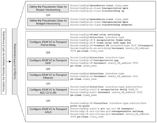
Figure 11-50 shows the configuration flowchart to configure Layer 2 VPN Interworking for various Layer 2 access technologies.
Figure 11-50. Configuring L2 VPN Interworking
Ethernet to VLAN Interworking
Figure 11-51 shows an MPLS provider network providing L2 VPN Interworking for Customer A site devices CE1-A and CE2-A. PE1 and PE2 are the PE routers in the MPLS provider network. CE1-A is connected via Ethernet to PE1, and CE2-A is connected via 802.1Q VLAN to PE2.
Figure 11-51. Configuring L2 VPN Interworking – Ethernet to VLAN
Configuration Steps – Ethernet to VLAN Interworking
The steps to configure Ethernet to VLAN Interworking between CE1-A and CE2-A are as follows:
|
Step 1. |
Define pseudo-wire class on PE routers – In this step, a pseudo-wire class called Eth-VLAN is defined on PE1 and VLAN-Eth on PE2. The configuration is shown in Example 11-37. This class configures the pseudo wire between the PE Routers PE1 and PE2. Ensure that the parameters of the pseudo-wire class are the same on both PEs to enable pseudo-wire establishment. Example 11-37 shows that AToM encapsulation (encapsulation mpls) and bridged interworking mode (interworking ethernet) will be used by the pseudo-wire class on the PE Routers PE1 and PE2. Example 11-37. Define Pseudo-Wire Class on PE Routers PE1(config)#pseudowire-class Eth-VLAN PE1(config-pw-class)# encapsulation mpls PE1(config-pw-class)# interworking ethernet ________________________________________________________________ PE2(config)#pseudowire-class VLAN-Eth PE2(config-pw-class)# encapsulation mpls PE2(config-pw-class)# interworking ethernet |
|
Step 2. |
Define AToM VC to transport Layer 2 frames – In this step, use the xconnect statement to define the AToM VC to carry the Layer 2 frames from CE1-A to CE2-A, and vice versa. Associate the pseudo-wire class defined in Step 1 with the AToM VC. See Example 11-38. Example 11-38. Define AToM VC to Transport Layer 2 Frames PE1(config)#interface Ethernet0/0 PE1(config-if)#xconnect 10.10.10.102 100 pw-class Eth-VLAN ________________________________________________________________ PE2(config)#interface Ethernet0/0.10 PE2(config-subif)# encapsulation dot1Q 10 PE2(config-subif)# xconnect 10.10.10.101 100 pw-class VLAN-Eth |
Final Configuration for Ethernet to VLAN Interworking
Figure 11-52 shows the final relevant configuration for customer and PE routers.
Figure 11-52. Final Configuration – Ethernet to VLAN
Verification of Ethernet to VLAN Interworking over MPLS
Verify AToM VC is up. Example 11-39 shows the output of show mpls l2transport vc in which the L2 transport VC is operational. The local circuit on PE1 is shown to be Ethernet on PE1 and Ethernet VLAN on PE2.
Example 11-39. Verify AToM VC Is Up
PE1#show mpls l2transport vc


Local intf Local circuit Dest address VC ID Status

------------- -------------------- --------------- ---------- ----------

Et0/0 Ethernet 10.10.10.102 100 UP

_________________________________________________________________________

PE2#show mpls l2transport vc


Local intf Local circuit Dest address VC ID Status

------------- -------------------- --------------- ---------- ----------

Et0/0.10 Eth VLAN 10 10.10.10.101 100 UP
Control Plane and Data Forwarding Operation
Figure 11-53 shows the control and data forwarding operation for Ethernet to VLAN interworking. From a control plane perspective, PE1 allocates VC label 18 for the Ethernet circuit connected to CE1-A. PE1 propagates this VC label 18 to PE2. As part of the IGP label operation, P1 assigns an LDP label 16 for PE1 (10.10.10.101) and propagates this to PE2. PE2 uses IGP label 16 to guide the data packet originating from CE2-A to CE1-A across the MPLS backbone.
Figure 11-53. Control and Data Plane Forwarding: Ethernet to VLAN
Frame Relay to AAL5 Interworking
Figure 11-54 shows an MPLS provider network providing L2 VPN Interworking for Customer A site devices CE1-A and CE2-A. PE1 and PE2 are the PE routers in the MPLS provider network. CE1-A is connected via ATM to PE1, and CE2-A is connected via Frame Relay to PE2.
Figure 11-54. L2 VPN Network – Frame Relay to AAL5
Configuration Steps – Frame Relay to AAL5 Interworking
The steps to configure Frame Relay to AAL5 Interworking between CE1-A and CE2-A are as follows:
|
Step 1. |
Define pseudo-wire class on PE routers – In this step, a pseudo-wire class called AAL5-FR is defined on PE1 and Fr-AAL5 on PE2. Example 11-40 shows that the AToM encapsulation (encapsulation mpls) and routed interworking model (interworking ip) is used by the pseudo-wire class on the PE routers PE1 and PE2. Example 11-40. Define Pseudo-Wire Class on PE Routers PE1(config)#pseudowire-class AAL5-FR PE1(config-pw-class)# encapsulation mpls PE1(config-pw-class)# interworking ip ________________________________________________________________ PE2(config)#pseudowire-class FR-AAL5 PE2(config-pw-class)# encapsulation mpls PE2(config-pw-class)# interworking ip |
|
Step 2. |
Define AToM VC to transport Layer 2 frames – In Example 11-41, use the xconnect statement to define the AToM VC to carry the Layer 2 frames from CE1-A to CE2-A and vice versa. Associate the pseudo-wire class defined in Step 1 with the AToM VC. Example 11-41. Define AToM VC to Transport Layer 2 Frames PE1(config-subif)#interface ATM6/0.100 point-to-point PE1(config-subif)# pvc 1/100 l2transport PE1(cfg-if-atm-l2trans-pvc)#encapsulation aal5snap PE1(cfg-if-atm-l2trans-pvc)#xconnect 10.10.10.102 100 pw-class AAL5-FR _________________________________________________________________________ PE2(config)#frame-relay switching PE2(config)#interface POS3/0 PE2(config-if)# no ip address PE2(config-if)# encapsulation frame-relay PE2(config-if)# clock source internal PE2(config-if)# frame-relay intf-type dce PE2(config-if)#connect FR POS3/0 100 l2transport PE2(config-fr-pw-switching)#xconnect 10.10.10.101 100 pw-class FR-AAL5 |
Verification of Frame Relay to AAL5 Interworking over MPLS
To verify Frame Relay to AAL5 interworking over MPLS, follow these steps:
|
Step 1. |
Verify if AToM VC is up – Example 11-42 shows the output of show mpls l2transport vc. The output indicates that the AToM VC is functional to transport L2 packets across the MPLS backbone. Example 11-42. Verification of ATOM VC Status PE1#show mpls l2transport vc Local intf Local circuit Dest address VC ID Status ------------- ----------------------- --------------- ---------- ---------- AT6/0.100 ATM AAL5 1/100 10.10.10.102 100 UP _____________________________________________________________________________ PE1#show mpls l2transport vc Local intf Local circuit Dest address VC ID Status ------------- ----------------------- --------------- ---------- ---------- PO3/0 FR DLCI 100 10.10.10.101 100 UP |
|
Step 2. |
Verify tunnel and VC label – Example 11-43 shows the output of show mpls l2transport vc detail. The output indicates the directed LDP peer is 10.10.10.102 and that the AToM VC is functional to transport L2 packets across the MPLS backbone. The VC ID is 100 and tunnel label is 17. This tunnel label is derived from LDP. The VC label on PE1 for outgoing interface on PE2 connected to CE2-A is 17, and it allocates VC label 23 for the interface connected to CE1-A. Example 11-43. Verification of Tunnel and VC Labels
PE1#show mpls l2transport vc detail

Local interface: AT6/0.100 up, line protocol up, ATM AAL5 1/100 up

 MPLS VC type is IP, interworking type is IP

 Destination address: 10.10.10.102, VC ID: 100, VC status: up

 Preferred path: not configured

 Default path: active

 Next hop: 10.10.10.2

 Output interface: Gi0/1, imposed label stack {17 17}

 Create time: 00:27:12, last status change time: 00:18:58

 Signaling protocol: LDP, peer 10.10.10.102:0 up

 MPLS VC labels: local 23, remote 17

 Group ID: local 6, remote 0

 MTU: local 4470, remote 4470

 Remote interface description:

 Sequencing: receive disabled, send disabled

 Sequence number: receive 0, send 0

 VC statistics:

 packet totals: receive 15, send 15

 byte totals: receive 1620, send 1620

 packet drops: receive 0, seq error 0, send 0

________________________________________________________________

PE2#show mpls l2transport vc detail

Local interface: PO3/0 up, line protocol up, FR DLCI 100 up

 MPLS VC type is IP, interworking type is IP

 Destination address: 10.10.10.101, VC ID: 100, VC status: up

 Preferred path: not configured

 Default path: active

 Next hop: 10.10.10.6

 Output interface: Gi0/1, imposed label stack {16 23}

 Create time: 00:18:39, last status change time: 00:18:35

 Signaling protocol: LDP, peer 10.10.10.101:0 up

 MPLS VC labels: local 17, remote 23

 Group ID: local 0, remote 6

 MTU: local 4470, remote 4470

 Remote interface description:

 Sequencing: receive disabled, send disabled

 Sequence number: receive 0, send 0

 VC statistics:

 packet totals: receive 15, send 15

 byte totals: receive 1620, send 1620

 packet drops: receive 0, seq error 0, send 0
|
|
Step 3. |
Verify MPLS forwarding table on the PE and P routers – Example 11-44 shows the LFIB on the PE routers in which PE1 allocates VC label 23 and PE2 allocates VC label 17. Example 11-44. Data Plane Forwarding Verification PE1#show mpls forwarding-table Local Outgoing Prefix Bytes tag Outgoing Next Hop tag tag or VC or Tunnel Id switched interface 16 Pop tag 10.10.10.4/30 0 Gi0/1 10.10.10.2 17 17 10.10.10.102/32 0 Gi0/1 10.10.10.2 21 Pop tag 10.10.10.100/32 0 Gi0/1 10.10.10.2 23 Untagged l2ckt(100) 1620 none point2point _______________________________________________________________________ P1#show mpls forwarding-table Local Outgoing Prefix Bytes Label Outgoing Next Hop Label Label or VC or Tunnel Id Switched interface 16 Pop Label 10.10.10.101/32 29489374 Gi0/1 10.10.10.1 17 Pop Label 10.10.10.102/32 5134192 Gi0/2 10.10.10.5 _______________________________________________________________________ PE2#show mpls forwarding-table Local Outgoing Prefix Bytes tag Outgoing Next Hop tag tag or VC or Tunnel Id switched interface 17 Untagged l2ckt(100) 1620 none point2point 18 Pop tag 10.10.10.0/30 0 Gi0/1 10.10.10.6 19 Pop tag 10.10.10.100/32 0 Gi0/1 10.10.10.6 20 16 10.10.10.101/32 0 Gi0/1 10.10.10.6 |
Frame Relay to PPP Interworking
Figure 11-55 shows an MPLS provider network using L2 VPN Interworking for Customer A sites with devices CE1-A and CE2-A. PE1 and PE2 are the PE routers in the MPLS provider network. CE1-A is connected using PPP encapsulation to PE1 and CE2-A is connected via Frame Relay to PE2.
Figure 11-55. Configuring L2 VPN Interworking – PPP to Frame Relay
Configuration Steps – Ethernet to VLAN Interworking
The steps to configure Ethernet to VLAN Interworking between CE1-A and CE2-A are as follows:
|
Step 1. |
Define pseudo-wire class on PE routers – In this step, pseudo-wire classes called PPP-FR and FR-PPP are defined on PE1 and PE2, respectively. The configuration is shown in Example 11-45. Ensure that the parameters of the pseudo-wire class are the same on both PEs; otherwise, the pseudo wire will not be established. Example 11-45. Define Pseudo-Wire Class on PE Routers PE1(config)#pseudowire-class FR-PPP PE1(config-pw-class)# encapsulation mpls PE1(config-pw-class)# interworking ip ________________________________________________________________ PE2(config)#pseudowire-class PPP-FR PE2(config-pw-class)# encapsulation mpls PE2(config-pw-class)# interworking ip |
|
Step 2. |
Define AToM VC to transport Layer 2 frames – Use the xconnect statement to define the AToM VC to carry the Layer 2 frames from CE1-A to CE2-A and vice versa. Associate the pseudo-wire class defined in Step 1 with the AToM VC. See Example 11-46. Example 11-46. Define ATOM VC to Transport Layer 2 Frames PE1(config-if)#interface Serial1/0 PE1(config-if)#no ip address PE1(config-if)#encapsulation frame-relay PE1(config-if)#frame-relay intf-type dce PE1(config-if)#exit PE1(config)#connect FR Serial1/0 100 l2transport PE1(config-fr-pw-switching)#xconnect 10.10.10.101 100 pw-class FR-PPP _______________________________________________________________________ PE2(config-if)#interface Serial1/0 PE2(config-subif)#encapsulation ppp PE2(config-subif)#xconnect 10.10.10.102 100 pw-class PPP-FR |
Verification of Frame Relay to PPP Interworking
To verify Frame Relay to PPP interworking, follow these steps:
|
Step 1. |
Ensure that AToM VC is up – Example 11-47 shows the output of show mpls l2transport vc. The output indicates that the AToM VC is functional to transport L2 packets across the MPLS backbone. Example 11-47. Verification of Atom VC Status PE1#show mpls l2transport vc Local intf Local circuit Dest address VC ID Status ------------- -------------------- --------------- ---------- ---------- Se2/1 FR DLCI 100 10.10.10.102 100 UP _________________________________________________________________________ PE2#show mpls l2transport vc Local intf Local circuit Dest address VC ID Status ------------- -------------------- --------------- ---------- ---------- Se2/1 PPP 10.10.10.101 100 UP |
|
Step 2. |
Verify tunnel and VC label – Example 11-48 shows the output of show MPLS l2transport binding. The output indicates the directed LDP peer is 10.10.10.102 and that the AToM VC is functional to transport L2 packets across the MPLS backbone. Example 11-48. Verification of Label Mappings PE1#show mpls l2transport binding Destination Address: 10.10.10.102, VC ID: 100 Local Label: 21 Cbit: 1, VC Type: IP, GroupID: 0 MTU: 1500, Interface Desc: connected to CE1-A VCCV Capabilities: None Remote Label: 16 Cbit: 1, VC Type: IP, GroupID: 0 MTU: 1500, Interface Desc: connected to CE2-A VCCV Capabilities: None |
|
Step 3. |
Example 11-49 shows the output of the show connection all command in which the Frame Relay switched connection is shown with Layer 2 VPN Interworking configured as well as the status of the segments. Example 11-49. show connection all Output on PE Router PE1#show connection all ID Name Segment 1 Segment 2 State ============================================================================ 1 FR Se2/1 100 10.10.10.102 100 UP __________________________________________________________________________ PE1#show connection id 1 FR/Pseudo-Wire Connection: 1 - FR Status - UP Segment 1 - Serial2/1 DLCI 100 Segment status: UP Line status: UP PVC status: ACTIVE NNI PVC status: ACTIVE Segment 2 - 10.10.10.102 100 Segment status: UP Requested AC state: UP PVC status: ACTIVE NNI PVC status: ACTIVE Interworking - ip |
Final Configurations for Devices to Implement Frame Relay to PPP Interworking
Figure 11-56 outlines the final configurations for the devices to implement L2 VPN Interworking between Frame Relay and PPP.
Figure 11-56. Final Device Configurations for L2 VPN Interworking: PPP to Frame Relay
Frame Relay to VLAN Interworking
Figure 11-57 shows an MPLS provider network using L2 VPN Interworking for Customer A sites with devices CE1-A and CE2-A as CE routers. PE1 and PE2 are the PE routers in the MPLS provider network. CE1-A is connected via 802.1Q VLAN to PE1, and CE2-A is connected via Frame Relay to PE2.
Figure 11-57. Frame Relay to VLAN Interworking Topology

Configuration Steps for Frame Relay to VLAN Interworking
The steps to configure Ethernet to VLAN interworking between CE1-A and CE2-A are as follows:
|
Step 1. |
Define pseudo-wire class on PE routers – In this step, a pseudo-wire class called VLAN-FR is defined on PE1 and Fr-VLAN on PE2. The configuration is shown in Example 11-50. Example 11-50. Step 1: Define Pseudo-Wire Class on PE Routers PE1(config)#pseudowire-class FR-VLAN PE1(config-pw-class)# encapsulation mpls PE1(config-pw-class)# interworking ip ________________________________________________________________ PE2(config)#pseudowire-class VLAN-FR PE2(config-pw-class)# encapsulation mpls PE2(config-pw-class)# interworking ip |
|
Step 2. |
Define AToM VC to transport Layer 2 frames – In this example, you use the xconnect statement to define the AToM VC to carry the Layer 2 frames from CE1-A to CE2-A and vice versa. Associate the pseudo-wire class defined in Step 1 with the AToM VC. See Example 11-51. Example 11-51. Step 2: Create AToM VC on PE Routers PE1(config-pw-class)#interface Serial2/1 PE1(config-if)# no ip address PE1(config-if)# encapsulation frame-relay PE1(config-if)# frame-relay intf-type dce PE1(config-if)#connect FR Serial2/1 100 l2transport PE1(config-fr-pw-switching)#xconnect 10.10.10.101 100 pw-class FR-VLAN _________________________________________________________________________ PE2(config-pw-class)#interface Ethernet0/0.10 PE2(config-subif)# encapsulation dot1Q 10 PE2(config-subif)#xconnect 10.10.10.102 100 pw-class VLAN-FR |
Verification of Frame Relay to VLAN Interworking over MPLS
To verify Frame Relay to VLAN Interworking over MPLS, follow these steps:
|
Step 1. |
Ensure that AToM VC is up – Example 11-52 shows the output of show MPLS l2transport vc. The output indicates that the AToM VC is functional to transport L2 packets across the MPLS backbone. Example 11-52. Verification of AToM VC Status PE1#show mpls l2transport vc Local intf Local circuit Dest address VC ID Status ------------- -------------------- --------------- ---------- ---------- Se2/1 FR DLCI 100 10.10.10.102 100 UP _________________________________________________________________________ PE2#show mpls l2transport vc Local intf Local circuit Dest address VC ID Status ------------- -------------------- --------------- ---------- ---------- Fa5/0.100 Eth VLAN 100 10.10.10.101 100 UP |
|
Step 2. |
Verify tunnel and VC label – Example 11-53 shows the output of show mpls l2transport binding. The output indicates the directed LDP peer is 10.10.10.102 and that the AToM VC is functional to transport L2 packets across the MPLS backbone. Example 11-53. Verify AToM Label Bindings PE1#show mpls l2transport binding Destination Address: 10.10.10.102, VC ID: 100 Local Label: 21 Cbit: 1, VC Type: IP, GroupID: 0 MTU: 1500, Interface Desc: connected to CE1-A VCCV Capabilities: None Remote Label: 20 Cbit: 1, VC Type: IP, GroupID: 0 MTU: 1500, Interface Desc: connected to CE2-A VCCV Capabilities: None |
|
Step 3. |
Example 11-54 shows the output of the show connection all command where the Frame Relay switched connection is depicted with Layer 2 VPN Interworking configured as well as the status of the segments. Example 11-54. Verification of L2 VPN Interworking Connections on PE Router PE1#show connection all ID Name Segment 1 Segment 2 State ============================================================================ 1 FR Se2/1 100 10.10.10.102 100 UP _____________________________________________________________________________ PE1#show connection id 1 FR/Pseudo-Wire Connection: 1 - FR Status - UP Segment 1 - Serial2/1 DLCI 100 Segment status: UP Line status: UP PVC status: ACTIVE NNI PVC status: ACTIVE Segment 2 - 10.10.10.102 100 Segment status: UP Requested AC state: UP PVC status: ACTIVE NNI PVC status: ACTIVE Interworking - ip |
Final Configuration for Frame Relay to VLAN Interworking
Figure 11-58 shows the final configurations for implementing Frame Relay to VLAN interworking.
Figure 11-58. Final Configurations for Frame Relay to VLAN Interworking
AAL5 to VLAN Interworking
Figure 11-59 shows an MPLS provider network that provides L2 VPN Interworking for Customer A sites with CE1-A and CE2-A as the CE devices. PE1 and PE2 are the PE routers in the MPLS provider network. CE1-A is connected via ATM to PE1, and CE2-A is connected via 802.1Q VLAN to PE2.
Figure 11-59. L2 VPN Interworking – ATM to VLAN Topology
Configuration Steps – VLAN to AAL5 Interworking
The steps to configure VLAN to AAL5 interworking between CE1-A and CE2-A are as follows:
|
Step 1. |
Define pseudo-wire class on PE routers – In this step, a pseudo-wire class, called Eth-VLAN, is defined on PE1 and VLAN-Eth on PE2. The configuration is shown in Example 11-55. Example 11-55. Step 1: Define Pseudo-Wire Class on PE Routers PE1(config)#pseudowire-class AAL5-VLAN PE1(config-pw-class)# encapsulation mpls PE1(config-pw-class)# interworking ip ________________________________________________________________ PE2(config)#pseudowire-class VLAN-AAL5 PE2(config-pw-class)# encapsulation mpls PE2(config-pw-class)# interworking ip |
|
Step 2. |
Define AToM VC to transport Layer 2 frames – Use the xconnect statement to define the AToM VC to carry the Layer 2 frames from CE1-A to CE2-A and vice versa. Associate the pseudo-wire class defined in Step 1 with the AToM VC. See Example 11-56. Example 11-56. Step 2: Create AToM VC on PE Routers PE1(config)#interface ATM3/0.100 point-to-point PE1(config)#mtu 1500 PE1(config-subif)# pvc 1/100 l2transport PE1(cfg-if-atm-l2trans-pvc)# encapsulation aal5snap PE1(cfg-if-atm-l2trans-pvc)#xconnect 10.10.10.102 100 pw-class AAL5-VLAN _________________________________________________________________________ PE2(config)#interface FastEthernet5/0.100 PE2(config-subif)# encapsulation dot1Q 100 PE2(config-subif)# xconnect 10.10.10.102 100 pw-class VLAN-AAL5 |
Verification of AAL5 to VLAN Interworking over MPLS
To verify AAL5 to VLAN Interworking over MPLS, follow these steps:
|
Step 1. |
Ensure that AToM VC is up – Example 11-57 shows the output of show mpls l2transport vc. The output indicates that the AToM VC is functional to transport L2 packets across the MPLS backbone. Example 11-57. Verification of AToM VC Status PE1#show mpls l2transport vc Local intf Local circuit Dest address VC ID Status ------------- -------------------- --------------- ---------- ---------- AT3/0.100 ATM AAL5 1/100 10.10.10.102 100 UP _________________________________________________________________________ PE2#show mpls l2transport vc Local intf Local circuit Dest address VC ID Status ------------- -------------------- --------------- ---------- ---------- Fa5/0.100 Eth VLAN 100 10.10.10.101 100 UP |
|
Step 2. |
Verify tunnel and VC label – Example 11-58 shows the output of show mpls l2transport binding. The output indicates the directed LDP peer is 10.10.10.102 and that the AToM VC is functional to transport L2 packets across the MPLS backbone. Example 11-58. Verify Label Assignment PE1#show mpls l2transport binding Destination Address: 10.10.10.102, VC ID: 100 Local Label: 16 Cbit: 1, VC Type: IP, GroupID: 0 MTU: 1500, Interface Desc: connected to CE1-A VCCV Capabilities: None Remote Label: 20 Cbit: 1, VC Type: IP, GroupID: 0 MTU: 1500, Interface Desc: connected to CE2-A VCCV Capabilities: None |
Final Device Configurations to Implement ATM to Ethernet VLAN Interworking
Figure 11-60 depicts the final configurations on the devices to implement ATM to Ethernet VLAN interworking.
Figure 11-60. Final Device Configurations for L2 VPN Interworking – ATM to VLAN
MPLS Overview
- MPLS Overview
- Unicast IP Forwarding in Traditional IP Networks
- Overview of MPLS Forwarding
- MPLS Terminology
- MPLS Control and Data Plane Components
- MPLS Operation
- Special Outgoing Label Types
- Penultimate Hop Popping
- Frame-Mode MPLS
- Cell-Mode MPLS
Basic MPLS Configuration
- Basic MPLS Configuration
- Frame-Mode MPLS Configuration and Verification
- Cell-Mode MPLS over ATM Overview, Configuration, and Verification
- Command Reference
Basic MPLS VPN Overview and Configuration
- Basic MPLS VPN Overview and Configuration
- VPN Categories
- MPLS VPN Architecture and Terminology
- MPLS VPN Routing Model
- MPLS VPN Basic Configuration
- Outbound Route Filters
- Command Reference
PE-CE Routing Protocol-Static and RIP
- PE-CE Routing Protocol-Static and RIP
- Static PE-CE Routing Overview, Configuration, and Verification
- Static PE-CE Routing Command Reference
- RIPv2 PE-CE Routing Overview, Configuration, and Verification
- RIPv1 PE-CE Routing Configuration and Verification
- RIP PE-CE Routing Command Reference
PE-CE Routing Protocol-OSPF and EIGRP
- PE-CE Routing Protocol-OSPF and EIGRP
- OSPF PE-CE Routing Protocol Overview, Configuration and Verification
- EIGRP PE-CE Routing Protocol Overview, Configuration, and Verification
Implementing BGP in MPLS VPNs
- Implementing BGP in MPLS VPNs
- BGP PE-CE Routing Protocol Overview, Configuration, and Verification
- Implementing Route-Reflectors in MPLS VPN Networks
- Case Study-Hub and Spoke MPLS VPN Network Using BGP PE-CE Routing for Sites Using Unique AS Numbers
- Case Study-Hub and Spoke MPLS VPN Network with Sites Using Same AS Numbers
- Command Reference
Inter-Provider VPNs
- Inter-Provider VPNs
- Overview of Inter-Provider VPNs
- Option 1: Inter-Provider VPN Using Back-to-Back VRF Method
- Option 2: Inter-Provider VPNs Using ASBR-to-ASBR Approach
- Option 3: Multi-Hop MP-eBGP Between RR and eBGP Between ASBRs
- Option 4: Non-VPN Transit Provider
- Case Study-Inter-AS Implementing Route-Reflector and BGP Confederation in Provider Networks
- Case Study-Multi-Homed Inter-AS Provider Network
- Command Reference
Carrier Supporting Carriers
- Carrier Supporting Carriers
- Carrier Supporting Carriers Overview
- Deployment Scenarios with CSC Architecture
- CSC Architecture Benefits
- Command Reference
MPLS Traffic Engineering
- MPLS Traffic Engineering
- TE Basics
- MPLS TE Theory
- Constraint-Based Routing and Operation in MPLS TE
- Configuring MPLS TE
- Command Reference
Implementing VPNs with Layer 2 Tunneling Protocol Version 3
- Implementing VPNs with Layer 2 Tunneling Protocol Version 3
- L2TPv3 Overview
- Configuring L2TPv3 Tunnels for Layer 2 VPN
- Configuring L2TPv3 Static Tunnels
- Configuring L2TPv3 Dynamic Tunnels
- Implementing Layer 3 VPNs over L2TPv3 Tunnels
- Command Reference
Any Transport over MPLS (AToM)
- Any Transport over MPLS (AToM)
- Introduction to Layer 2 VPNs
- Implementing AToM for Like to Like Circuits
- L2 VPN-Any to Any Interworking
- Local Switching
- Command Reference
Virtual Private LAN Service (VPLS)
- Virtual Private LAN Service (VPLS)
- VPLS Overview
- VPLS Topology-Single PE or Direct Attachment
- Hierarchical VPLS-Distributed PE Architecture
- Command Reference
Implementing Quality of Service in MPLS Networks
- Implementing Quality of Service in MPLS Networks
- Introduction to QoS-Classification and Marking
- MPLS QoS Implementation
- MPLS QoS Operating Modes
- Modular QoS CLI: Configuration of QoS on Cisco Routers
- Configuration and Implementation of MPLS QoS in Uniform Mode and Short Pipe Mode Operation
- Implementing MPLS QoS for Layer 2 VPN Implementations
- Command Reference
MPLS Features and Case Studies
- MPLS Features and Case Studies
- Case Study 1: Implementing Multicast Support for MPLS VPNs
- Case Study 2: Implementing Multi-VRF CE, VRF Selection Using Source IP Address, VRF Selection Using Policy-Based Routing, NAT and HSRP Support in MPLS VPN, and Multicast VPN Support over Multi-VRF CE
- Case Study 3: Implementing Layer 2 VPNs over Inter-AS Topologies Using Layer 2 VPN Pseudo-Wire Switching
- Case Study 4: Implementing Layer 3 VPNs over Layer 2 VPN Topologies and Providing L2 VPN Redundancy
- Case Study 5: Implementing Dynamic Layer 3 VPNs Using mGRE Tunnels
- Case Study 6: Implementing Class-Based Tunnel Selection with MPLS Traffic Engineering
- Case Study 7: Implementing Hub and Spoke Topologies with OSPF
- Case Study 8: Implementing Hub and Spoke Topologies with EIGRP
- Case Study 9: Implementing VPLS Services with the GSR 12000 Series
- Case Study 10: BGP Site of Origin
- Command Reference
EAN: 2147483647
Pages: 130
