BGP PE-CE Routing Protocol Overview, Configuration, and Verification
BGP version 4 (BGP4) is the current de facto Internet standard for inter-domain (AS) exterior routing. In MPLS VPN networks, MP-BGP is used and plays a pivotal role in the transportation of VPNv4 prefixes across the service provider network. In traditional environments, customer networks prefer to use BGP in their networks and, therefore, use BGP as a PE-CE routing protocol when migrating from a non-MPLS based to an MPLS VPN based network. This helps the customer establish a consistent end-to-end routing policy. In an MPLS VPN network, BGP attributes for a VPN site are transparently transported across the service provider backbone to another site in the same VPN. Because there is a single routing protocol used across the VPN between service provider core and customer sites, the concept of redistribution does not apply.
BGP PE-CE peering in an MPLS VPN environment can be performed in two different ways:
- BGP PE-CE VPN sites implementing unique AS numbers
- BGP PE-CE VPN sites implementing same AS numbers
In the MPLS VPN network shown in Figure 6-1, an MPLS VPN service provider plans to provision BGP PE-CE routing protocol for two customers, Customers A and B. CE1-A and CE2-A are CE devices belonging to Customer A located at Site 1 and Site 2, respectively. They are part of the same VPN, VPN-A. These CE devices are connected to provider edge devices PE1-AS1 and PE2-AS1 in the service provider network. CE1-A belongs to AS 65001 and CE2-A belongs to AS 65002. For Customer B network, CE1-A and CE2-A are the CE devices located at Site 1 and Site 2, respectively, and are part of the VPN, VPN-B. CE1-A and CE2-A belong to AS 65001 and are connected to PE1-AS1 and PE2-AS1, respectively.
Figure 6-1. MPLS VPN Provider Provisioning BGP PE-CE Routing
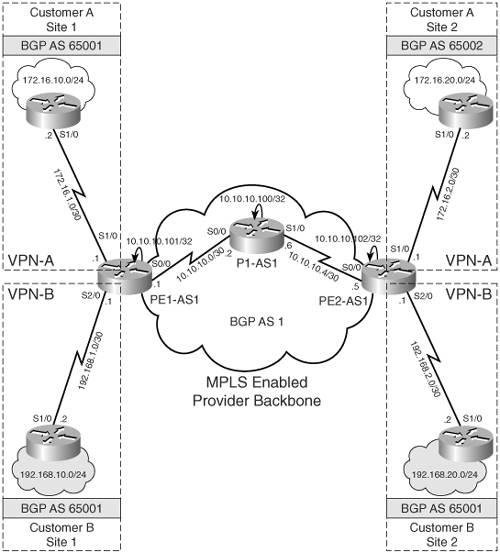
Implementing BGP PE-CE routing for the Customer A network is not an issue because the VPN sites use unique AS numbers. However, Customer B plans on using the same AS number on its sites. This causes an issue when migrating from a traditional non-MPLS based network topology, where the customer might use the same AS numbers at all his sites, to an MPLS VPN-based infrastructure due to the BGP loop prevention mechanism. The BGP loop prevention mechanism disallows customer sites having identical AS numbers to be linked by another AS number. In other words, if such a case occurs, routing updates from one site would be dropped when the other site receives them; therefore, connectivity cannot be established between the sites without additional configuration on the SP PE routers.
To explain this further, Figure 6-2 shows an MPLS VPN network provisioned for Customer B. As shown in Figure 6-2, BGP loop prevention mechanism on CE2-B finds 65001 in the AS-PATH; therefore, CE2-B rejects the 192.168.10.0/24 update from PE2-AS1 because it finds its own AS in the update.
Figure 6-2. BGP Loop Prevention Mechanism
To circumvent the BGP loop prevention mechanism, the AS-PATH update procedure in BGP was modified. The current AS-PATH update procedure allows customer topologies to reuse AS numbers at the sites by using the AS Override functionality. The functionality is made active only when the first AS number in the AS-PATH is equal to the AS number of the receiving BGP router. As shown in Figure 6-2, the first AS number in the AS-PATH is 65001, which is the AS number of CE2-B, the receiving router.
Figure 6-3 shows the AS Override functionality when identical AS numbers are used at customer sites. The AS Override function causes all leading occurrences of the AS number of the receiving BGP router to be replaced with the AS number of the sending BGP router. As shown in Step 3 of Figure 6-3, when AS Override is used, AS 65001 in the AS-PATH is replaced with the AS number of the sending BGP router PE2-AS1, which is 1. Any other occurrences (further down the AS-PATH) of the receiving router's AS number are not replaced because they indicate a real routing information loop. In addition, an extra copy of the sending router's AS number is prepended to the AS-PATH (standard AS number prepending procedure that occurs on every eBGP update) to maintain proper AS hop count for proper BGP route selection. Step 3 in Figure 6-3 shows that PE2-AS1 prepends AS 1 to BGP update.
Figure 6-3. AS Override Functionality
Configuration Flowchart to Implement BGP PE-CE Routing for VPN Sites with Unique and Same AS Numbers
Figure 6-4 shows the configuration flowchart to configure BGP PE-CE routing for VPN sites using unique and same BGP AS.
Figure 6-4. Configuration Flowchart for BGP PE-CE VPN Sites Implementing Unique and Similar AS
Implementing BGP PE-CE Routing for VPN Sites With Unique and Same AS Numbers
This configuration scenario demonstrates BGP PE-CE routing for VPN sites using same and different BGP AS numbers. You will use the topology shown in Figure 6-1, in which Customer A is using BGP AS 65001 and 65002 at Sites 1 and 2, respectively, and Customer B uses the same AS 65001 at both the sites. Before configuring, ensure that the provider network is provisioned to deliver MPLS VPN services to Customer A sites. It is also assumed that IP addresses are preconfigured and VRFs defined on PE routers. Example 6-1 provides the configuration steps defining VRF and its attributes on PE routers for BGP PE-CE routing.
Example 6-1. Define VRF Cust_A and Cust_B on PE Routers PE1-AS1 and PE2-AS1
PE1-AS1(config)#ip vrf Cust_A

PE1-AS1(config-vrf)# rd 1:100

PE1-AS1(config-vrf)# route-target both 1:100

PE1-AS1(config)#interface Serial1/0

PE1-AS1(config-if)# description connected to CE1-A

PE1-AS1(config-if)# ip vrf forwarding Cust_A

PE1-AS1(config-if)# ip address 172.16.1.1 255.255.255.252

PE1-AS1(config)#ip vrf Cust_B

PE1-AS1(config-vrf)# rd 1:200

PE1-AS1(config-vrf)# route-target both 1:200

PE1-AS1(config)#interface Serial2/0

PE1-AS1(config-if)# description connected to CE2-B

PE1-AS1(config-if)# ip vrf forwarding Cust_B

PE1-AS1(config-if)# ip address 192.168.1.1 255.255.255.252
The steps to configure BGP PE-CE routing on PE routers are as follows:
|
Step 1. |
Configure per VRF BGP routing context on PE routers – Configure per VRF BGP routing contexts for Cust_A and Cust_B under the BGP routing process on PE1-AS1 and PE2-AS1. Example 6-2 demonstrates the per VRF BGP configuration on PE1-AS1. Repeat the steps on PE2-AS1. Note that the address-family IPv4 VRF contexts are seen by default in a router's configuration when relevant configurations for forming MP-iBGP sessions are configured on PE routers. In that case, address-family ipv4 vrf vrf-name command under the BGP routing process is keyed in to enter a particular VRF's IPv4 address-family context so that further configurations can be performed (as shown in Step 2). Example 6-2. Configure per VRF BGP Routing Context on PE Routers PE1-AS1(config)#router bgp 1 PE1-AS1(config-router)#address-family ipv4 vrf Cust_A PE1-AS1(config)#router bgp 1 PE1-AS1(config-router)#address-family ipv4 vrf Cust_B |
|
Step 2. |
Define and activate BGP CE neighbors – In this step, under the BGP VRF routing context created in Step 1, the remote BGP CE neighbors are defined on the PE routers and activated. Example 6-3 shows the configuration to define BGP CE neighbors on the PE routers. Example 6-3. Define and Activate BGP CE Neighbors PE1-AS1(config-router-af)#neighbor 172.16.1.2 remote-as 65001 PE1-AS1(config-router-af)#neighbor 172.16.1.2 activate ________________________________________________________________ PE2-AS1(config-router-af)#neighbor 172.16.2.2 remote-as 65002 PE2-AS1(config-router-af)#neighbor 172.16.2.2 activate ________________________________________________________________ PE1-AS1(config-router-af)#neighbor 192.168.1.2 remote-as 65001 PE1-AS1(config-router-af)#neighbor 192.168.1.2 as-override PE1-AS1(config-router-af)#neighbor 192.168.1.2 activate ________________________________________________________________ PE2-AS1(config-router-af)#neighbor 192.168.2.2 remote-as 65001 PE2-AS1(config-router-af)#neighbor 192.168.2.2 as-override PE2-AS1(config-router-af)#neighbor 192.168.2.2 activate |
CE Router Configuration
Example 6-4 shows the configuration on Routers CE CE1-A, CE2-A, CE1-B, and CE2-B.
Example 6-4. CE1-A, CE2-A, CE1-B, and CE2-B Configuration
hostname CE1-A

!

interface Ethernet0/0

description Customer A Site 1 network

 ip address 172.16.10.1 255.255.255.0

!

interface Serial1/0

description connected to PE1-AS1

 ip address 172.16.1.2 255.255.255.252

!

router bgp 65001

 no synchronization

network 172.16.10.0 mask 255.255.255.0

 neighbor 172.16.1.1 remote-as 1

 no auto-summary

__________________________________________________________________________

hostname CE2-A

!

interface Ethernet0/0

description Customer A Site 2 network

 ip address 172.16.20.1 255.255.255.0

!

interface Serial1/0

description connected to PE2-AS1

ip address 172.16.2.2 255.255.255.252

!

router bgp 65002

 no synchronization

network 172.16.20.0 mask 255.255.255.0

 neighbor 172.16.2.1 remote-as 1

 no auto-summary

__________________________________________________________________________

hostname CE1-B

!

interface Ethernet0/0

 description Customer B Site 1 network

 ip address 192.168.10.1 255.255.255.0

!

interface Serial1/0

description connected to PE1-AS1

 ip address 192.168.1.2 255.255.255.252

!

router bgp 65001

 no synchronization

 network 192.168.10.0

 neighbor 192.168.1.1 remote-as 1

 no auto-summary

__________________________________________________________________________

hostname CE2-B

!

interface Ethernet0/0

 description Customer B Site 2 network

 ip address 192.168.20.1 255.255.255.0

!

interface Serial1/0

 description connected to PE2-AS1

 ip address 192.168.2.2 255.255.255.252

!

router bgp 65001

 no synchronization

 network 192.168.20.0

 neighbor 192.168.2.1 remote-as 1

 no auto-summary
Final Configuration for BGP PE-CE VPN Sites Implementing Unique and Same BGP AS Numbers
Example 6-5 shows the detailed and final configurations on the PE1-AS1, PE2-AS1, and P1-AS1 routers.
Example 6-5. PE1-AS1, PE2-AS1, and P1-AS1 Final Configuration for BGP PE-CE VPN Sites Implementing Unique BGP AS
hostname PE1-AS1

!

ip cef

!

ip vrf Cust_A

 rd 1:100

 route-target export 1:100

 route-target import 1:100

!

ip vrf Cust_B

 rd 1:200

 route-target export 1:200

 route-target import 1:200

!

mpls ldp router-id Loopback0

!

interface Loopback0

 ip address 10.10.10.101 255.255.255.255

!

interface Serial0/0

 description connected to P1-AS1

 ip address 10.10.10.1 255.255.255.252

 mpls ip

!

interface Serial1/0

 description connected to CE1-A

 ip vrf forwarding Cust_A

 ip address 172.16.1.1 255.255.255.252

!

interface Serial2/0

 description connected to CE1-B

 ip vrf forwarding Cust_B

 ip address 192.168.1.1 255.255.255.252

!

router ospf 1

 router-id 10.10.10.101

 network 10.0.0.0 0.255.255.255 area 0

!

router bgp 1

 no synchronization

 neighbor 10.10.10.102 remote-as 1

 neighbor 10.10.10.102 update-source Loopback0

 no auto-summary

 !

 address-family vpnv4

 neighbor 10.10.10.102 activate

 neighbor 10.10.10.102 send-community extended

 exit-address-family

 !

 address-family ipv4 vrf Cust_B

 neighbor 192.168.1.2 remote-as 65001

 neighbor 192.168.1.2 activate

 neighbor 192.168.1.2 as-override

 no auto-summary

 no synchronization

 exit-address-family

 !

 address-family ipv4 vrf Cust_A

 neighbor 172.16.1.2 remote-as 65001

 neighbor 172.16.1.2 activate

 no auto-summary

 no synchronization

 exit-address-family

__________________________________________________________________________

hostname PE2-AS1

!

ip cef

!

ip vrf Cust_A

 rd 1:100

 route-target export 1:100

 route-target import 1:100

!

ip vrf Cust_B

 rd 1:200

 route-target export 1:200

 route-target import 1:200

!

mpls ldp router-id Loopback0

!

interface Loopback0

 ip address 10.10.10.102 255.255.255.255

!

interface Serial0/0

 description connected to P1-AS1

 ip address 10.10.10.5 255.255.255.252

 mpls ip

!

interface Serial1/0

 description connected to CE2-A

 ip vrf forwarding Cust_A

 ip address 172.16.2.1 255.255.255.252

!

interface Serial2/0

 description connected to CE2-B

 ip vrf forwarding Cust_B

 ip address 192.168.2.1 255.255.255.252

!

router ospf 1

 router-id 10.10.10.102

 network 10.0.0.0 0.255.255.255 area 0

!

router bgp 1

 no synchronization

 neighbor 10.10.10.101 remote-as 1

 neighbor 10.10.10.101 update-source Loopback0

 no auto-summary

 !

 address-family vpnv4

 neighbor 10.10.10.101 activate

 neighbor 10.10.10.101 send-community extended

 exit-address-family

 !

 address-family ipv4 vrf Cust_B

 neighbor 192.168.2.2 remote-as 65001

 neighbor 192.168.2.2 activate

 neighbor 192.168.2.2 as-override

 no auto-summary

 no synchronization

 exit-address-family

 !

 address-family ipv4 vrf Cust_A

 neighbor 172.16.2.2 remote-as 65002

 neighbor 172.16.2.2 activate

 no auto-summary

 no synchronization

 exit-address-family

__________________________________________________________________________

hostname P1-AS1

!

ip cef

!

interface Loopback0

 ip address 10.10.10.200 255.255.255.255

!

interface Serial0/0

description connected to PE1-AS1

 ip address 10.10.10.2 255.255.255.252

 mpls ip

!

interface Serial1/0

description connected to PE2-AS1

 ip address 10.10.10.6 255.255.255.252

 mpls ip

!

router ospf 1

 log-adjacency-changes

 network 10.0.0.0 0.255.255.255 area 0
Verifying BGP PE-CE Routing for VPN Sites Implementing Unique and Different BGP AS Numbers
The steps to verify BGP PE-CE routing for VPN sites implementing unique and different BGP AS numbers are
|
Step 1. |
Verify BGP neighbor relationship on PE1-AS1 and PE2-AS1 – Verify the BGP neighbor relationship between PE-CE routers. Example 6-6 shows that the BGP neighbor relationship is established between PE1-AS1 and CE routers CE1-A and CE2-B. PE1-AS1 has received two prefixes from PE2-AS1 (10.10.10.102) and one from each CE router. The BGP neighbor relationship can also be verified by issuing show ip bgp neighbor ip-address. Example 6-6. show ip bgp vpnv4 all summary on PE Routers PE1-AS1#show ip bgp vpnv4 all summary Neighbor V AS MsgRcvd MsgSent TblVer InQ OutQ Up/Down State/PfxRcd 10.10.10.102 4 1 11 11 9 0 0 00:06:30 2 172.16.1.2 4 65001 11 11 9 0 0 00:06:06 1 192.168.1.2 4 65001 11 11 9 0 0 00:06:05 1 ______________________________________________________________________________ PE2-AS1#show ip bgp vpnv4 all summary Neighbor V AS MsgRcvd MsgSent TblVer InQ OutQ Up/Down State/PfxRcd 10.10.10.101 4 1 12 12 9 0 0 00:07:23 2 172.16.2.2 4 65002 12 12 9 0 0 00:07:30 1 192.168.2.2 4 65001 12 12 9 0 0 00:07:30 1 |
|
Step 2. |
Verify VRF routing table on PE1-AS1 and PE2-AS1 – Check VRFs Cust_A and Cust_B routing table to see if CE networks are received by the connected PE routers. Example 6-7 outlines that PE1-AS1 has received CE2-A network (172.16.20.0/24) from the PE2-AS1 router and 172.16.10.0/24 from the connected CE router, CE1-A. Example 6-7. VRF Routing Table on PE Routers PE1-AS1#show ip route vrf Cust_A bgp 172.16.0.0/16 is variably subnetted, 3 subnets, 2 masks B 172.16.20.0/24 [200/0] via 10.10.10.102, 00:07:10 B 172.16.10.0/24 [20/0] via 172.16.1.2, 00:07:38 ________________________________________________________________ PE1-AS1#show ip route vrf Cust_B bgp B 192.168.10.0/24 [20/0] via 192.168.1.2, 00:07:43 B 192.168.20.0/24 [200/0] via 10.10.10.102, 00:07:15 ________________________________________________________________ PE2-AS1#show ip route vrf Cust_A bgp 172.16.0.0/16 is variably subnetted, 3 subnets, 2 masks B 172.16.20.0/24 [20/0] via 172.16.2.2, 00:08:30 B 172.16.10.0/24 [200/0] via 10.10.10.101, 00:08:15 ________________________________________________________________ PE2-AS1#show ip route vrf Cust_B bgp B 192.168.10.0/24 [200/0] via 10.10.10.101, 00:08:18 B 192.168.20.0/24 [20/0] via 192.168.2.2, 00:08:33 |
|
Step 3. |
Verify BGP VPNv4 routing table on PE1-AS1 and PE2-AS1 – Check the BGP VPNv4 routing table to verify CE networks on the PE routers. Example 6-8 shows PE1-AS1 has 172.16.20.0/24 and 192.168.20.0/24 prefixes in the BGP table from the remote PE router, PE2-AS1, and 172.16.10.0 and 192.168.10.0 from the local CE routers, CE1-A and CE1-B. Similar output is also seen on PE2-AS1. Example 6-8. VPNv4 Routing Table on PE Routers PE1-AS1#show ip bgp vpnv4 all BGP table version is 9, local router ID is 10.10.10.101 Status codes: s suppressed, d damped, h history, * valid, > best, i - internal, r RIB-failure, S Stale Origin codes: i - IGP, e - EGP, ? - incomplete Network Next Hop Metric LocPrf Weight Path Route Distinguisher: 1:100 (default for vrf Cust_A) *> 172.16.10.0/24 172.16.1.2 0 0 65001 i *>i172.16.20.0/24 10.10.10.102 0 100 0 65002 i Route Distinguisher: 1:200 (default for vrf Cust_B) *> 192.168.10.0 192.168.1.2 0 0 65001 i *>i192.168.20.0 10.10.10.102 0 100 0 65001 i _______________________________________________________________________________ PE2-AS1#show ip bgp vpnv4 all BGP table version is 9, local router ID is 10.10.10.102 Status codes: s suppressed, d damped, h history, * valid, > best, i - internal, r RIB-failure, S Stale Origin codes: i - IGP, e - EGP, ? - incomplete Network Next Hop Metric LocPrf Weight Path Route Distinguisher: 1:100 (default for vrf Cust_A) *>i172.16.10.0/24 10.10.10.101 0 100 0 65001 i *> 172.16.20.0/24 172.16.2.2 0 0 65002 i Route Distinguisher: 1:200 (default for vrf Cust_B) *>i192.168.10.0 10.10.10.101 0 100 0 65001 i *> 192.168.20.0 192.168.2.2 0 0 65001 i |
|
Step 4. |
Verify end-to-end connectivity via ping – Verify end-to-end connectivity between CE1-A and CE2-A by issuing a ping from CE1-A to network 172.16.20.1/24 on CE2-A and vice versa. Example 6-9 shows the result of the ping operation. Example 6-9. Verify End-to-End Connectivity on CE Routers CE1-A#ping 172.16.20.1 source 172.16.10.1 Type escape sequence to abort. Sending 5, 100-byte ICMP Echos to 172.16.20.1, timeout is 2 seconds: Packet sent with a source address of 172.16.10.1 !!!!! Success rate is 100 percent (5/5), round-trip min/avg/max = 76/79/84 ms _______________________________________________________________________ CE1-B#ping 192.168.20.1 source 192.168.10.1 Type escape sequence to abort. Sending 5, 100-byte ICMP Echos to 192.168.20.1, timeout is 2 seconds: Packet sent with a source address of 192.168.10.1 !!!!! Success rate is 100 percent (5/5), round-trip min/avg/max = 80/80/84 ms |
MPLS Overview
- MPLS Overview
- Unicast IP Forwarding in Traditional IP Networks
- Overview of MPLS Forwarding
- MPLS Terminology
- MPLS Control and Data Plane Components
- MPLS Operation
- Special Outgoing Label Types
- Penultimate Hop Popping
- Frame-Mode MPLS
- Cell-Mode MPLS
Basic MPLS Configuration
- Basic MPLS Configuration
- Frame-Mode MPLS Configuration and Verification
- Cell-Mode MPLS over ATM Overview, Configuration, and Verification
- Command Reference
Basic MPLS VPN Overview and Configuration
- Basic MPLS VPN Overview and Configuration
- VPN Categories
- MPLS VPN Architecture and Terminology
- MPLS VPN Routing Model
- MPLS VPN Basic Configuration
- Outbound Route Filters
- Command Reference
PE-CE Routing Protocol-Static and RIP
- PE-CE Routing Protocol-Static and RIP
- Static PE-CE Routing Overview, Configuration, and Verification
- Static PE-CE Routing Command Reference
- RIPv2 PE-CE Routing Overview, Configuration, and Verification
- RIPv1 PE-CE Routing Configuration and Verification
- RIP PE-CE Routing Command Reference
PE-CE Routing Protocol-OSPF and EIGRP
- PE-CE Routing Protocol-OSPF and EIGRP
- OSPF PE-CE Routing Protocol Overview, Configuration and Verification
- EIGRP PE-CE Routing Protocol Overview, Configuration, and Verification
Implementing BGP in MPLS VPNs
- Implementing BGP in MPLS VPNs
- BGP PE-CE Routing Protocol Overview, Configuration, and Verification
- Implementing Route-Reflectors in MPLS VPN Networks
- Case Study-Hub and Spoke MPLS VPN Network Using BGP PE-CE Routing for Sites Using Unique AS Numbers
- Case Study-Hub and Spoke MPLS VPN Network with Sites Using Same AS Numbers
- Command Reference
Inter-Provider VPNs
- Inter-Provider VPNs
- Overview of Inter-Provider VPNs
- Option 1: Inter-Provider VPN Using Back-to-Back VRF Method
- Option 2: Inter-Provider VPNs Using ASBR-to-ASBR Approach
- Option 3: Multi-Hop MP-eBGP Between RR and eBGP Between ASBRs
- Option 4: Non-VPN Transit Provider
- Case Study-Inter-AS Implementing Route-Reflector and BGP Confederation in Provider Networks
- Case Study-Multi-Homed Inter-AS Provider Network
- Command Reference
Carrier Supporting Carriers
- Carrier Supporting Carriers
- Carrier Supporting Carriers Overview
- Deployment Scenarios with CSC Architecture
- CSC Architecture Benefits
- Command Reference
MPLS Traffic Engineering
- MPLS Traffic Engineering
- TE Basics
- MPLS TE Theory
- Constraint-Based Routing and Operation in MPLS TE
- Configuring MPLS TE
- Command Reference
Implementing VPNs with Layer 2 Tunneling Protocol Version 3
- Implementing VPNs with Layer 2 Tunneling Protocol Version 3
- L2TPv3 Overview
- Configuring L2TPv3 Tunnels for Layer 2 VPN
- Configuring L2TPv3 Static Tunnels
- Configuring L2TPv3 Dynamic Tunnels
- Implementing Layer 3 VPNs over L2TPv3 Tunnels
- Command Reference
Any Transport over MPLS (AToM)
- Any Transport over MPLS (AToM)
- Introduction to Layer 2 VPNs
- Implementing AToM for Like to Like Circuits
- L2 VPN-Any to Any Interworking
- Local Switching
- Command Reference
Virtual Private LAN Service (VPLS)
- Virtual Private LAN Service (VPLS)
- VPLS Overview
- VPLS Topology-Single PE or Direct Attachment
- Hierarchical VPLS-Distributed PE Architecture
- Command Reference
Implementing Quality of Service in MPLS Networks
- Implementing Quality of Service in MPLS Networks
- Introduction to QoS-Classification and Marking
- MPLS QoS Implementation
- MPLS QoS Operating Modes
- Modular QoS CLI: Configuration of QoS on Cisco Routers
- Configuration and Implementation of MPLS QoS in Uniform Mode and Short Pipe Mode Operation
- Implementing MPLS QoS for Layer 2 VPN Implementations
- Command Reference
MPLS Features and Case Studies
- MPLS Features and Case Studies
- Case Study 1: Implementing Multicast Support for MPLS VPNs
- Case Study 2: Implementing Multi-VRF CE, VRF Selection Using Source IP Address, VRF Selection Using Policy-Based Routing, NAT and HSRP Support in MPLS VPN, and Multicast VPN Support over Multi-VRF CE
- Case Study 3: Implementing Layer 2 VPNs over Inter-AS Topologies Using Layer 2 VPN Pseudo-Wire Switching
- Case Study 4: Implementing Layer 3 VPNs over Layer 2 VPN Topologies and Providing L2 VPN Redundancy
- Case Study 5: Implementing Dynamic Layer 3 VPNs Using mGRE Tunnels
- Case Study 6: Implementing Class-Based Tunnel Selection with MPLS Traffic Engineering
- Case Study 7: Implementing Hub and Spoke Topologies with OSPF
- Case Study 8: Implementing Hub and Spoke Topologies with EIGRP
- Case Study 9: Implementing VPLS Services with the GSR 12000 Series
- Case Study 10: BGP Site of Origin
- Command Reference
EAN: 2147483647
Pages: 130
