Option 2: Inter-Provider VPNs Using ASBR-to-ASBR Approach
Option 2 Inter Provider VPNs Using ASBR to ASBR Approach
In the back-to-back VRF method, ASBRs use traditional IPv4 routing to integrate VPNs across two adjacent service provider networks. In the second method, the ASBRs use MP-eBGP to peer with each other to transport VPNv4 routes between autonomous systems. This is called the ASBR-to-ASBR approach, also known as MP-eBGP for VPNv4 exchange. This approach, therefore, alleviates the need to have per-VPN configuration on the ASBRs as seen in the back-to-back VRF method, and, thus, allows VPNv4 prefixes to be transported across multiple providers. However, to allow the transportation of VPNv4 prefixes, the link between the autonomous systems must support the exchange of MPLS packets because the VPNv4 updates are encapsulated in MPLS packets when they traverse an AS and so need to be encapsulated when going across (between) the autonomous systems.
To understand the concept of ASBR-to-ASBR operation, it is necessary to understand how traditional MPLS VPN forwarding takes place. In an MPLS VPN network, packet forwarding takes place only if the router specified as the BGP next hop in the incoming BGP update is the same as the router that assigned the VPN label in the MPLS VPN label stack. However, when VPNs are geographically dispersed across multiple service providers, the BGP next-hop attribute is changed when there is an eBGP session between the ASBRs. Therefore, in an ASBR-to-ASBR method, a VPN label is assigned whenever the BGP next hop is changed. The ASBR-to-ASBR approach accommodates the use of MP-eBGP between ASBRs to transport VPNv4 prefixes versus the MP-iBGP implementation in traditional VPN networks within a single AS. The only difference between MP-iBGP and MP-eBGP when transporting VPNv4 prefixes is the way the next-hop attribute is handled. Because the next hop is changed when there is an eBGP session between the ASBR, the LSP path terminates on the ASBR originating the update. As a result, the advertising ASBR has to assign a new label for the route before sending it via the MP-eBGP update to its ASBR peer.
There are some important characteristics to keep in mind when using the ASBR-to-ASBR approach:
- There is no requirement of TDP/LDP or any IGP to be enabled on the link connecting the two ASBRs. The MP-eBGP session between directly connected interfaces on the ASBRs enables the interfaces to forward labeled packets.
- no bgp default route-target filter needs to be configured on an ASBR that does not have any VRFs configured or is functioning as a RR. The command ensures that the ASBR accepts the BGP VPNv4 prefixes from other PE routers inside the AS. The default behavior is to deny incoming VPNv4 prefixes that are not otherwise imported into any local VRF.
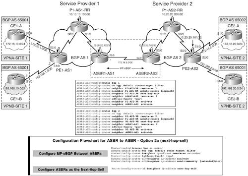
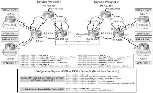
Figure 7-9 shows a multiprovider MPLS VPN network. ASBR1-AS1 and ASBR2-AS2 belong to different provider networks.
Figure 7-9. Multiprovider Network Using ASBR-ASBR Approach
The three methods of transporting VPNv4 prefixes between the two ASBRs are as follows:
- Option 2a – Next-hop-self method
- Option 2b – Redistribute connected method
- Option 2c – eBGP between ASBRs and MP-eBGP between RRs
The following sections discuss each of these approaches in greater detail.
Option 2a: ASBR-ASBR Approach Using Next-Hop-Self Method
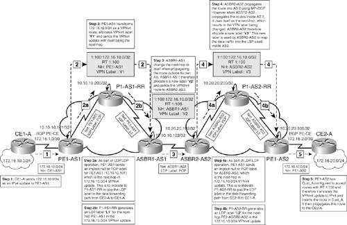
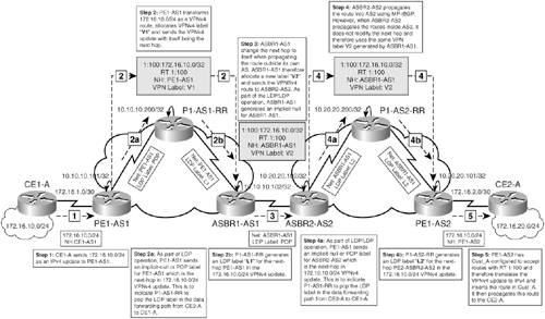
Figure 7-9 shows an Inter-AS VPN network. In this topology, when the next-hop-self approach is used, ASBR1-AS1 announces itself as the next hop to P1-AS1-RR, and, similarly, ASBR2-AS2 announces itself as the next hop to P1-AS2-RR. Because the next hop is modified, a new VPNv4 label has to be generated. The eBGP border router ASBR1-AS1 distributes the route to ASBR2-AS2 in the adjoining AS, specifying its own address as eBGP next hop, and assigns a new VPNv4 label. This label is propagated to ASBR2-AS2. ASBR2-AS2 receives the VPNv4 route on the MP-eBGP session from ASBR1-AS1. The next-hop-self is again used and, as a result, the next hop is modified from ASBR1-AS1 to ASBR2-AS2 when ASBR2-AS2 propagates these routes via the MP-iBGP session to P1-AS2-RR. Because the next hop is modified, the VPN label is modified as well and will be used by ASBR2-AS2 to map incoming traffic from PE2-AS2 into the correct LSP toward ASBR2-AS2. This is demonstrated in the following section.
Control Plane Forwarding in Option 2a
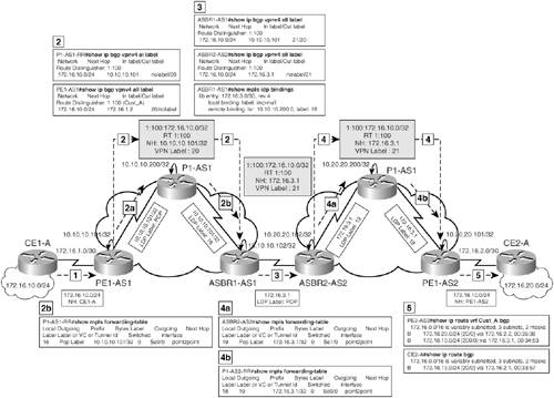
Figure 7-10 shows the control plane forwarding action that takes place for prefix 172.16.10.0/24 advertised by CE1-A to CE2-A in Customer A network.
Figure 7-10. Control Plane Forwarding in Option 2a
Data Forwarding in Option 2a
Figure 7-11 traces the path of the data packet from the source network, 172.16.20.0/24, to the destination network, 172.16.10.0/24.
Figure 7-11. Data Plane Forwarding in Option 2a
Configuration Flowchart to Implement Inter-Provider VPN Operation Using Option 2a
Figure 7-12 shows the configuration flowchart to accomplish a functional Inter-AS network using the ASBR-to-ASBR approach. As shown in the flowchart, the first step is to configure MP-eBGP between the ASBRs. The second step is to define the ASBRs as the next hop in their respective BGP autonomous systems.
Figure 7-12. Configuration Flowchart for Option 2a
Configuration Step to Implement Inter-Provider VPN Operation Using Option 2a
To configure inter-provider VPNs using the ASBR-to-ASBR (next-hop-self) approach, configure the ASBRs for MP-eBGP exchange. Configure the ASBR Routers ASBR1 and ASBR2 for MP-eBGP exchange. Ensure no bgp default route-target filter is configured under the BGP routing process. Define the BGP relationship with the RR and configure the ASBR-AS1 as the next hop for all updates originating from ASBR1-AS1 to P1-AS1-RR. This is shown in Example 7-7. Repeat the same steps on ASBR2-AS2.
Example 7-7. Configure ASBRs for MP-eBGP
ASBR1-AS1(config)#router bgp 1

ASBR1-AS1(config-router)# no bgp default route-target filter

ASBR1-AS1(config-router)# neighbor 172.16.3.2 remote-as 2

ASBR1-AS1(config-router)# address-family vpnv4

ASBR1-AS1(config-router-af)# neighbor 172.16.3.2 activate

ASBR1-AS1(config-router-af)# neighbor 10.10.10.200 next-hop-self

__________________________________________________________________________

ASBR2-AS2(config)#router bgp 2

ASBR2-AS2(config-router)# no bgp default route-target filter

ASBR2-AS2(config-router)# neighbor 172.16.3.1 remote-as 1

ASBR2-AS2(config-router)# address-family vpnv4

ASBR2-AS2(config-router-af)# neighbor 172.16.3.1 activate

ASBR2-AS2(config-router-af)# neighbor 10.20.20.200 next-hop-self
ASBR1-AS1 and ASBR2-AS2 Final Configurations for Option 2a
Example 7-8 shows the ASBR1-AS1 and ASBR2-AS2 configurations when using the next-hop-self approach. For PE1-AS1, P1-AS1-RR, P1-AS2-RR, and PE2-AS2 (PE1-AS2 in option 1) configurations, refer to configurations used in option 1 – back-to-back VRF method.
Example 7-8. ASBR1-AS1 and ASBR2-AS2 Final Configurations
hostname ASBR1-AS1

!

ip cef

!

mpls ldp router-id Loopback0

!

interface Loopback0

 ip address 10.10.10.102 255.255.255.255

!

interface Serial0/0

 description connected to P1-AS1

 ip address 10.10.10.5 255.255.255.252

 mpls ip

!

interface Serial1/0

 ip address 172.16.3.1 255.255.255.252

 mpls bgp forwarding

!

router ospf 1

 router-id 10.10.10.102

 network 10.0.0.0 0.255.255.255 area 0

!

router bgp 1

 no bgp default ipv4-unicast

 no bgp default route-target filter

 neighbor 10.10.10.200 remote-as 1

 neighbor 10.10.10.200 update-source Loopback0

 neighbor 172.16.3.2 remote-as 2

 !

 address-family ipv4

 neighbor 10.10.10.200 activate

 neighbor 172.16.3.2 activate

 no auto-summary

 no synchronization

 exit-address-family

 !

 address-family vpnv4

 neighbor 10.10.10.200 activate

 neighbor 10.10.10.200 send-community extended

 neighbor 10.10.10.200 next-hop-self

 neighbor 172.16.3.2 activate

 neighbor 172.16.3.2 send-community extended

 exit-address-family

__________________________________________________________________________

hostname ASBR2-AS2

!

ip cef

!

mpls ldp router-id Loopback0

!

interface Loopback0

 ip address 10.20.20.102 255.255.255.255

!

interface Serial0/0

 description connected to P1-AS2

 ip address 10.20.20.5 255.255.255.252

 mpls ip

!

interface Serial1/0

 ip address 172.16.3.2 255.255.255.252

 mpls bgp forwarding

!

router ospf 2

 router-id 10.20.20.102

 network 10.0.0.0 0.255.255.255 area 0

!

router bgp 2

 no bgp default ipv4-unicast

 no bgp default route-target filter

 neighbor 10.20.20.200 remote-as 2

 neighbor 10.20.20.200 update-source Loopback0

 neighbor 172.16.3.1 remote-as 1

 !

address-family ipv4

neighbor 10.20.20.200 activate

neighbor 172.16.3.1 activate

no auto-summary

no synchronization

exit-address-family

!

address-family vpnv4

neighbor 10.20.20.200 activate

neighbor 10.20.20.200 send-community extended

neighbor 10.20.20.200 next-hop-self

neighbor 172.16.3.1 activate

neighbor 172.16.3.1 send-community extended

exit-address-family
Verifying Inter-Provider VPN Operation Using Option 2a
The steps to verify inter-provider VPN operation using next-hop-self method are
|
Step 1. |
Verify control plane – Figure 7-13 shows the control plane forwarding operation when the 172.16.10.0/24 prefix is propagated across the multiprovider networks AS1 and AS2 to CE2-A. Figure 7-13. Verify Control Plane Forwarding 
|
|
Step 2. |
Verify data forwarding – Figure 7-14 shows the data plane forwarding operation when the 172.16.10.0/24 prefix is propagated across the multiprovider networks AS1 and AS2 to CE2-A. Figure 7-14. Verify Data Plane Forwarding 
|
|
Step 3. |
Verify end-to-end connectivity via ping – Verify end-to-end connectivity between Customer A sites and Customer B sites. Example 7-9 shows the result of the ping. Example 7-9. Verify End-to-End Connectivity CE1-A#ping 172.16.20.1 source 172.16.10.1 Type escape sequence to abort. Sending 5, 100-byte ICMP Echos to 172.16.20.1, timeout is 2 seconds: Packet sent with a source address of 172.16.10.1 !!!!! Success rate is 100 percent (5/5), round-trip min/avg/max = 140/140/140 ms __________________________________________________________________________ CE1-B#ping 192.168.20.1 source 192.168.10.1 Type escape sequence to abort. Sending 5, 100-byte ICMP Echos to 192.168.20.1, timeout is 2 seconds: Packet sent with a source address of 192.168.10.1 !!!!! Success rate is 100 percent (5/5), round-trip min/avg/max = 132/138/140 ms |
Option 2b: ASBR-to-ASBR Approach Using Redistribute Connected
In the redistribute connected approach, the receiving ASBR accepts the route without changing the next-hop attribute and any label information. The receiving ASBR also creates a /32 host route for its ASBR neighbor so as to access the next-hop address for the prefix. This host route must be redistributed into the IGP using the redistribute connected command.
Control Plane Forwarding in Option 2b
Figure 7-15 shows the control plane forwarding action that takes place for prefix 172.16.10.0/24 advertised by CE1-A to CE2-A that belongs to the same VPN CUST_A.
Figure 7-15. Control Plane Forwarding Using Option 2b
Data Forwarding in Option 2b
The source and destination networks belonging to the same VPN, VPN-A, are located on two different MPLS VPN provider networks. The data forwarding path originates from the source address of the flow, which is 172.16.20.1 destined to the 172.16.10.1. Figure 7-16 traces the path of the data packet from the source to the destination.
Figure 7-16. Data Plane Forwarding Using Option 2b
Configuration Flowchart for Implementing Option 2b
Figure 7-17 shows the configuration flowchart to configure option 2b.
Figure 7-17. Configuration Flowchart for Option 2b
Configuring Inter-Provider VPNs Using Option 2b
In this section, the topology shown in Figure 7-9 is used, and the configuration steps are shown only for routers that are responsible for Inter-AS operations. You can use the PE1-AS1, P1-AS1-RR, P1-AS2-RR, and PE1-AS2 configurations used in back-to-back VRF for the ASBR-to-ASBR approach. The only exceptions would be
- Hostname for PE1-AS2 changes to PE2-AS2.
- Hostname PE2-AS1-ASBR1 and PE2-AS2-ASBR2 change to ASBR1-AS1 and ASBR2-AS2, respectively, because the ASBR performs a single function of transporting VPNv4 prefixes and not the dual function of a PE router, as seen in the back-to-back VRF method.
The steps to configure inter-provider VPNs using the redistribute connected approach are
|
Step 1. |
Configure ASBRs for MP-eBGP exchange – Configure the ASBR Routers ASBR1 and ASBR2 for MP-eBGP exchange. Ensure no bgp default route-target filter is configured under the BGP routing process. This step is the same as Step 1 shown in section "Configuration Step to Implement Inter-Provider VPN Operation Using Option 2a" except the next-hop-self statement in redistribute connected approach is not used. |
|
Step 2. |
Redistribute the connected host routes in BGP – Example 7-11 shows the step to redistribute connected routes (see Example 7-10) in OSPF. The host connected routes were created when the MP-eBGP session between the ASBRs was established. Example 7-10. Connected Host Routes on ASBR1-AS1 and ASBR2-AS2 ASBR1-AS1#show ip route | include 172.16.3 C 172.16.3.2/32 is directly connected, Serial1/0 C 172.16.3.0/30 is directly connected, Serial1/0 _____________________________________________________________________ ASBR2-AS2#show ip route | include 172.16.3 C 172.16.3.1/32 is directly connected, Serial1/0 C 172.16.3.0/30 is directly connected, Serial1/0 Example 7-11. Redistribute the Connected Host Routes in BGP ASBR1-AS1(config)#router ospf 1 ASBR1-AS1(config-router)#redistribute connected subnets route-map net_172.16.3.0 ASBR1-AS1(config-router)#exit ASBR1-AS1(config)#route-map net_172.16.3.0 permit 10 ASBR1-AS1(config-route-map)# match ip address net_172.16.3.0 ASBR1-AS1(config-route-map)#exit ASBR1-AS1(config)#ip access-list standard net_172.16.3.0 ASBR1-AS1(config-std-nacl)# permit 172.16.3.0 0.0.0.3 _________________________________________________________________________________ ASBR2-AS2(config)#router ospf 2 ASBR2-AS2(config-router)#redistribute connected subnets route-map net_172.16.3.0 ASBR2-AS2(config-router)#exit ASBR2-AS2(config)#route-map net_172.16.3.0 permit 10 ASBR2-AS2(config-route-map)# match ip address net_172.16.3.0 ASBR2-AS2(config-route-map)#exit ASBR2-AS2(config)#ip access-list standard net_172.16.3.0 ASBR2-AS2(config-std-nacl)# permit 172.16.3.0 0.0.0.3 |
Final Router Configurations for ASBRs in Option 2b
Example 7-12 shows ASBR1-AS1 and ASBR2-AS2 configurations when using the redistribute connected approach in ASBR-to-ASBR. They reflect only the necessary configurations required to implement this methodology. The remaining configurations are similar to ASBR1-AS1 and ASBR-AS2 configurations in option 2a, next-hop-self method, excluding the next-hop-self statement.
Example 7-12. ASBR1-AS1 and ASBR2-AS2 Configurations When Using the Redistribute Connected Approach in ASBR-ASBR
hostname ASBR1-AS1

!

router ospf 1

 router-id 10.10.10.102

 redistribute connected subnets route-map net_172.16.3.0

 network 10.0.0.0 0.255.255.255 area 0

!

router bgp 1

 no bgp default ipv4-unicast

 no bgp default route-target filter

 bgp log-neighbor-changes

 neighbor 10.10.10.200 remote-as 1

 neighbor 10.10.10.200 update-source Loopback0

 neighbor 172.16.3.2 remote-as 2

 !

 address-family ipv4

 neighbor 10.10.10.200 activate

 neighbor 172.16.3.2 activate

 no auto-summary

 no synchronization

 exit-address-family

 !

 address-family vpnv4

 neighbor 10.10.10.200 activate

 neighbor 10.10.10.200 send-community extended

 neighbor 172.16.3.2 activate

 neighbor 172.16.3.2 send-community extended

 exit-address-family

!

ip access-list standard net_172.16.3.0

 permit 172.16.3.0 0.0.0.3

!

route-map net_172.16.3.0 permit 10

 match ip address net_172.16.3.0

__________________________________________________________________________

hostname ASBR2-AS2

!

router ospf 2

 router-id 10.20.20.102

 redistribute connected subnets route-map net_172.16.3.0

 network 10.0.0.0 0.255.255.255 area 0

!

router bgp 2

 no bgp default ipv4-unicast

 no bgp default route-target filter

 bgp log-neighbor-changes

 neighbor 10.20.20.200 remote-as 2

 neighbor 10.20.20.200 update-source Loopback0

 neighbor 172.16.3.1 remote-as 1

 !

 address-family ipv4

 neighbor 10.20.20.200 activate

 neighbor 172.16.3.1 activate

 no auto-summary

 no synchronization

 exit-address-family

 !

 address-family vpnv4

 neighbor 10.20.20.200 activate

 neighbor 10.20.20.200 send-community extended

neighbor 172.16.3.1 activate

 neighbor 172.16.3.1 send-community extended

 exit-address-family

!

ip access-list standard net_172.16.3.0

 permit 172.16.3.0 0.0.0.3

!

route-map net_172.16.3.0 permit 10

 match ip address net_172.16.3.0
Verification of Control Plane Forwarding When Using Option 2b
Figure 7-18 shows the control plane forwarding operation when the 172.16.10.0/24 prefix is propagated across the multiprovider networks AS1 and AS2 to CE2-A.
Figure 7-18. Verification of Control Plane Forwarding When Using Option 2b
Verification of Data Forwarding in Option 2b
Figure 7-19 traces the path of the data packet from the source to the destination.
Figure 7-19. Data Plane Forwarding Using Option 2b
Option 2c: Multi-Hop MP-eBGP Between ASBRs
Option 2c is a variant of Option 2a and 2b where the ASBR routers provide transportation of VPNv4 prefixes from AS1 to AS2 and vice versa. Figure 7-20 shows a multiprovider VPN network that is providing VPN services to it sites belonging to Customer A. P1-AS1-RR and P1-AS2-RR are RRs that are local in each of the provider's network. An MP-eBGP session is formed between the ASBRs to transport VPNv4 information across the multiprovider network. To maintain an end-to-end LSP path, MPLS is enabled between the ASBRs.
Figure 7-20. Control Plane Forwarding in Option 2c
Control Plane Forwarding in Option 2c
Figure 7-20 shows the control plane forwarding action that takes place for prefix 172.16.10.0/24 advertised by CE1-A to CE2-A that belongs to the same VPN CUST_A.
Data Plane Forwarding in Option 2c
The source and destination networks are located on two different MPLS VPN provider networks. The data forwarding path originates from the source address of the flow, which is 172.16.20.1 destined to 172.16.10.1. Figure 7-21 traces the path of the data packet from the source to the destination.
Figure 7-21. Data Plane Forwarding in Option 2c
Configuring Multi-Hop MP-eBGP Between ASBRs
Figure 7-22 shows an MPLS VPN network in which sites in VPN-A are geographically dispersed. Site 1 and Site 2 in VPN-A have CE routers CE1-A and CE2-A, which connect to PE routers PE1-AS1 and PE1-AS2 located in Service Provider 1 and Service Provider 2, respectively. The network shown in Figure 7-22 has two ASBRs, ASBR1 and ASBR2, which are connected to each other via a single link.
Figure 7-22. Configuration Steps in Option 2c
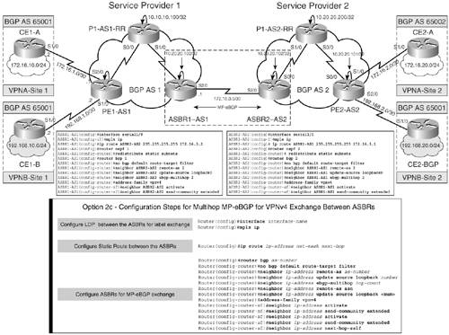
Configuration Flowchart for Implementing Option 2c
Figure 7-22 shows the configuration steps that are involved in accomplishing a functional Inter-AS network using multi-hop MP-eBGP between ASBRs:
|
Step 1. |
Configure LDP between the ASBRs for label exchange – Enable the interface between the ASBRs for IPv4 label exchange. Example 7-13 demonstrates the step. Example 7-13. Configure LDP Between the ASBRs for Label Exchange ASBR1-AS1(config)#interface serial1/0 ASBR1-AS1(config-if)#mpls ip ________________________________________________________________ ASBR2-AS2(config)#interface serial1/0 ASBR2-AS2(config-f)#mpls ip |
|
Step 2. |
Configure IGP for ASBR reachability – Configure static routes to the loopback address on ASBR1-AS1 and ASBR2-AS2. Redistribute the static routes in the OSPF. Example 7-14 shows the configuration to ensure ASBR reachability. Example 7-14. Configure IGP for ASBR Reachability ASBR1-AS1(config)#interface Loopback0 ASBR1-AS1(config-if)#ip address 10.10.10.102 255.255.255.255 ASBR1-AS1(config-if)#exit ASBR1-AS1(config)#ip route 10.20.20.102 255.255.255.255 172.16.3.2 ASBR1-AS1(config)#router ospf 1 ASBR1-AS1(config-router)#redistribute static subnets ___________________________________________________________________ ASBR1-AS2(config)#interface Loopback0 ASBR1-AS2(config-if)#ip address 10.20.20.102 255.255.255.255 ASBR1-AS2(config-if)#exit ASBR2-AS2(config)# ip route 10.10.10.102 255.255.255.255 172.16.3.1 ASBR2-AS2(config)#router ospf 2 ASBR2-AS2(config-router)# redistribute static subnets |
|
Step 3. |
Configure multi-hop MP-eBGP between ASBRs for VPNv4 exchange – Configure the ASBR Routers ASBR1-AS1 and ASBR2-AS2 for MP-eEBGP, as shown in Example 7-15. Example 7-15. Configure Multi-Hop MP-eEBGP Between ASBRs for VPNv4 Exchange ASBR1-AS1(config)#router bgp 1 ASBR1-AS1(config-router)#no bgp default route-target filter ASBR1-AS1(config-router)#neighbor 10.20.20.102 remote-as 2 ASBR1-AS1(config-router)#neighbor 10.20.20.102 update-source loopback0 ASBR1-AS1(config-router)#neighbor 10.20.20.102 ebgp-multihop 2 ASBR1-AS1(config-router)#address-family vpnv4 ASBR1-AS1(config-router-af)#neighbor 10.20.20.102 activate ______________________________________________________________________ ASBR2-AS2(config)#router bgp 2 ASBR2-AS2(config-router)#no bgp default route-target filter ASBR2-AS2(config-router)#neighbor 10.10.10.102 remote-as 2 ASBR2-AS2(config-router)#neighbor 10.10.10.102 update-source loopback0 ASBR2-AS2(config-router)#neighbor 10.10.10.102 ebgp-multihop 2 ASBR2-AS2(config-router)#address-family vpnv4 ASBR2-AS2(config-router-af)#neighbor 10.10.10.102 activate |
ASBR1-AS1 and ASBR2-AS2 Configurations for Option 2c
Example 7-16 shows the ASBR1-AS1 and ASBR2-AS2 configurations when using multi-hop MP-eBGP between the ASBRs.
Example 7-16. ASBR1-AS1 and ASBR2-AS2 Configurations
! ASBR1-AS1

interface Serial1/0

 ip address 172.16.3.1 255.255.255.252

 mpls ip

!

router ospf 1

 router-id 10.10.10.102

 redistribute static subnets

 network 10.0.0.0 0.255.255.255 area 0

!

router bgp 1

 no bgp default ipv4-unicast

 no bgp default route-target filter

 neighbor 10.10.10.200 remote-as 1

 neighbor 10.10.10.200 update-source Loopback0

 neighbor 10.20.20.102 remote-as 2

 neighbor 10.20.20.102 ebgp-multihop 2

 neighbor 10.20.20.102 update-source Loopback0

 !

 address-family ipv4

 neighbor 10.10.10.200 activate

 no auto-summary

 no synchronization

 exit-address-family

 !

 address-family vpnv4

 neighbor 10.10.10.200 activate

 neighbor 10.10.10.200 send-community extended

 neighbor 10.20.20.102 activate

 neighbor 10.20.20.102 send-community extended

 exit-address-family

!

ip route 10.20.20.102 255.255.255.255 172.16.3.2

__________________________________________________________________________

! ASBR2-AS2

interface Serial1/0

 ip address 172.16.3.2 255.255.255.252

 mpls ip

!

router ospf 2

 router-id 10.20.20.102

 redistribute connected

 redistribute static subnets

 network 10.0.0.0 0.255.255.255 area 0

!

router bgp 2

 no bgp default ipv4-unicast

 no bgp default route-target filter

 neighbor 10.10.10.102 remote-as 1

 neighbor 10.10.10.102 ebgp-multihop 2

 neighbor 10.10.10.102 update-source Loopback0

 neighbor 10.20.20.200 remote-as 2

 neighbor 10.20.20.200 update-source Loopback0

!

 address-family vpnv4

 neighbor 10.10.10.102 activate

 neighbor 10.10.10.102 send-community extended

 neighbor 10.20.20.200 activate

 neighbor 10.20.20.200 send-community extended

 exit-address-family

!

ip route 10.10.10.102 255.255.255.255 172.16.3.1
Verifying Inter-Provider VPN Operation Option 2c
The steps to verify inter-provider VPN operation option 2c are
|
Step 1. |
Verification of control plane forwarding – Figure 7-23 shows the control plane forwarding operation when the 172.16.10.0/24 prefix is propagated across the multiprovider networks AS1 and AS2 to CE2-A. Figure 7-23. Verify Control Plane Forwarding 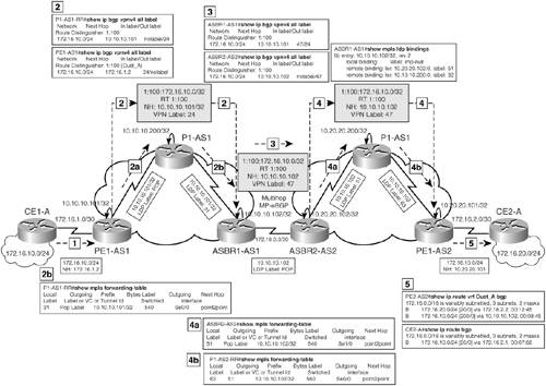
|
|
Step 2. |
Verification of data plane forwarding – Figure 7-24 shows the data plane forwarding operation when the 172.16.10.0/24 prefix is propagated across the multiprovider networks, AS1 and AS2, to CE2-A. Figure 7-24. Verify Data Plane Forwarding 
|
|
Step 3. |
Verify end-to-end connectivity via ping – Verify end-to-end connectivity between CE1-B and CE2-B by issuing a ping from CE1-B to network 172.16.20.1/24 on CE2-B and vice versa. Example 7-17 shows the result of the ping operation. Example 7-17. Verify End-to-End Connectivity CE1-A#ping 172.16.20.1 source 172.16.10.1 Type escape sequence to abort. Sending 5, 100-byte ICMP Echos to 172.16.20.1, timeout is 2 seconds: Packet sent with a source address of 172.16.10.1 !!!!! Success rate is 100 percent (5/5), round-trip min/avg/max = 140/140/140 ms __________________________________________________________________________ CE1-B#ping 192.168.20.1 source 192.168.10.1 Type escape sequence to abort. Sending 5, 100-byte ICMP Echos to 192.168.20.1, timeout is 2 seconds: Packet sent with a source address of 192.168.10.1 !!!!! Success rate is 100 percent (5/5), round-trip min/avg/max = 132/138/140 ms |
MPLS Overview
- MPLS Overview
- Unicast IP Forwarding in Traditional IP Networks
- Overview of MPLS Forwarding
- MPLS Terminology
- MPLS Control and Data Plane Components
- MPLS Operation
- Special Outgoing Label Types
- Penultimate Hop Popping
- Frame-Mode MPLS
- Cell-Mode MPLS
Basic MPLS Configuration
- Basic MPLS Configuration
- Frame-Mode MPLS Configuration and Verification
- Cell-Mode MPLS over ATM Overview, Configuration, and Verification
- Command Reference
Basic MPLS VPN Overview and Configuration
- Basic MPLS VPN Overview and Configuration
- VPN Categories
- MPLS VPN Architecture and Terminology
- MPLS VPN Routing Model
- MPLS VPN Basic Configuration
- Outbound Route Filters
- Command Reference
PE-CE Routing Protocol-Static and RIP
- PE-CE Routing Protocol-Static and RIP
- Static PE-CE Routing Overview, Configuration, and Verification
- Static PE-CE Routing Command Reference
- RIPv2 PE-CE Routing Overview, Configuration, and Verification
- RIPv1 PE-CE Routing Configuration and Verification
- RIP PE-CE Routing Command Reference
PE-CE Routing Protocol-OSPF and EIGRP
- PE-CE Routing Protocol-OSPF and EIGRP
- OSPF PE-CE Routing Protocol Overview, Configuration and Verification
- EIGRP PE-CE Routing Protocol Overview, Configuration, and Verification
Implementing BGP in MPLS VPNs
- Implementing BGP in MPLS VPNs
- BGP PE-CE Routing Protocol Overview, Configuration, and Verification
- Implementing Route-Reflectors in MPLS VPN Networks
- Case Study-Hub and Spoke MPLS VPN Network Using BGP PE-CE Routing for Sites Using Unique AS Numbers
- Case Study-Hub and Spoke MPLS VPN Network with Sites Using Same AS Numbers
- Command Reference
Inter-Provider VPNs
- Inter-Provider VPNs
- Overview of Inter-Provider VPNs
- Option 1: Inter-Provider VPN Using Back-to-Back VRF Method
- Option 2: Inter-Provider VPNs Using ASBR-to-ASBR Approach
- Option 3: Multi-Hop MP-eBGP Between RR and eBGP Between ASBRs
- Option 4: Non-VPN Transit Provider
- Case Study-Inter-AS Implementing Route-Reflector and BGP Confederation in Provider Networks
- Case Study-Multi-Homed Inter-AS Provider Network
- Command Reference
Carrier Supporting Carriers
- Carrier Supporting Carriers
- Carrier Supporting Carriers Overview
- Deployment Scenarios with CSC Architecture
- CSC Architecture Benefits
- Command Reference
MPLS Traffic Engineering
- MPLS Traffic Engineering
- TE Basics
- MPLS TE Theory
- Constraint-Based Routing and Operation in MPLS TE
- Configuring MPLS TE
- Command Reference
Implementing VPNs with Layer 2 Tunneling Protocol Version 3
- Implementing VPNs with Layer 2 Tunneling Protocol Version 3
- L2TPv3 Overview
- Configuring L2TPv3 Tunnels for Layer 2 VPN
- Configuring L2TPv3 Static Tunnels
- Configuring L2TPv3 Dynamic Tunnels
- Implementing Layer 3 VPNs over L2TPv3 Tunnels
- Command Reference
Any Transport over MPLS (AToM)
- Any Transport over MPLS (AToM)
- Introduction to Layer 2 VPNs
- Implementing AToM for Like to Like Circuits
- L2 VPN-Any to Any Interworking
- Local Switching
- Command Reference
Virtual Private LAN Service (VPLS)
- Virtual Private LAN Service (VPLS)
- VPLS Overview
- VPLS Topology-Single PE or Direct Attachment
- Hierarchical VPLS-Distributed PE Architecture
- Command Reference
Implementing Quality of Service in MPLS Networks
- Implementing Quality of Service in MPLS Networks
- Introduction to QoS-Classification and Marking
- MPLS QoS Implementation
- MPLS QoS Operating Modes
- Modular QoS CLI: Configuration of QoS on Cisco Routers
- Configuration and Implementation of MPLS QoS in Uniform Mode and Short Pipe Mode Operation
- Implementing MPLS QoS for Layer 2 VPN Implementations
- Command Reference
MPLS Features and Case Studies
- MPLS Features and Case Studies
- Case Study 1: Implementing Multicast Support for MPLS VPNs
- Case Study 2: Implementing Multi-VRF CE, VRF Selection Using Source IP Address, VRF Selection Using Policy-Based Routing, NAT and HSRP Support in MPLS VPN, and Multicast VPN Support over Multi-VRF CE
- Case Study 3: Implementing Layer 2 VPNs over Inter-AS Topologies Using Layer 2 VPN Pseudo-Wire Switching
- Case Study 4: Implementing Layer 3 VPNs over Layer 2 VPN Topologies and Providing L2 VPN Redundancy
- Case Study 5: Implementing Dynamic Layer 3 VPNs Using mGRE Tunnels
- Case Study 6: Implementing Class-Based Tunnel Selection with MPLS Traffic Engineering
- Case Study 7: Implementing Hub and Spoke Topologies with OSPF
- Case Study 8: Implementing Hub and Spoke Topologies with EIGRP
- Case Study 9: Implementing VPLS Services with the GSR 12000 Series
- Case Study 10: BGP Site of Origin
- Command Reference
EAN: 2147483647
Pages: 130
