Cell-Mode MPLS
When using ATM connectivity between devices, MPLS applies to cells, not frames. Cells are used to transport data plane information. When ATM labels are used in an MPLS core, the operating mode of MPLS is called cell-mode MPLS. As previously mentioned, peering between LSRs via routed ATM PVCs can also be implemented but is considered a frame-mode implementation.
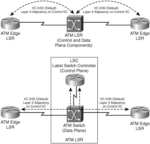
In cell-mode MPLS, the LSRs in the core of the MPLS network are ATM switches that forward data based on the ATM header. If the ATM LSR functions as a pure ATM switch (data plane), an external control plane component also called the label switch controller (LSC) is required for propagation of control plane information. In some cases, however, the ATM LSR is capable of propagating control plane information as well as forwarding data plane information and thus does not require an external control plane component.
When the ATM LSR has an external LSC component for control plane information exchange, the ATM switch in the ATM LSR performs only data plane forwarding. To enable MPLS in the ATM domain, the VPI/VCI field in the ATM header is used as the label. Therefore, a label is inserted between the ATM header and IP header, and the VPI/VCI field of the ATM header forwards the cells. This mechanism allows for data plane forwarding of labeled packets. Control plane packets, such as protocol information exchange in routing protocols and label distribution protocols, are exchanged between edge ATM LSRs and the control plane component of the ATM LSR over a control virtual circuit (control VC).
In cell-mode MPLS, the label used in the MPLS domain is the same format as the regular MPLS label, as shown earlier in Figure 1-6. To ensure that cells are forwarded using MPLS, the VPI/VCI values forward the labeled cells. This label is inserted between the ATM header and the IP header in the cells that are forwarded to the ATM LSR, as shown in Figure 1-17.
Figure 1-17. Cell-Mode MPLS Label Imposition
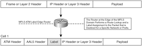
Figure 1-18 shows a cell-mode MPLS network with an ingress edge ATM LSR, a core ATM LSR, and an egress edge ATM LSR. The interfaces of the LSRs in the MPLS domain that carry pure cells are called Label Switching controlled-ATM interfaces (LC-ATM) as the VPI/VCI pairs for the virtual circuits are used by the protocol for distribution and exchange of labels in the ATM domain. ATM-LSR is an ATM switch that runs MPLS on the control plane and performs MPLS forwarding between LC-ATM interfaces on the data plane by means of traditional ATM cell switching. In the integrated ATM LSR implementation, the LC-ATM interfaces carry both the data plane packets as well as the control plane packets (on VC 0/32). If an ATM switch is connected to an external LSC together functioning as the ATM LSR, the Edge ATM LSRs form a control plane adjacency with the LSC, and the LSC identifies the data plane forwarding (ingress labels to egress label mappings) on the LSC-ATM interfaces of the ATM switch in the ATM LSR.
Figure 1-18. Cell-Mode MPLS Domain
As portrayed in Figure 1-18, a control plane adjacency is required between adjoining ATM switches or LSRs in the ATM domain for IGP and label distribution protocol packet exchange. To ensure appropriate forwarding of IP routing information through an ATM switch, all the ATM LSRs and ATM Edge LSRs form an IP adjacency by creating an in-band VC that is used only for control information. The VPI/VCI used for this control VC is 0/32 (default) and needs to be configured on all ATM switches and ATM Edge LSRs in the MPLS ATM domain. Therefore, the MPLS control VC is configured by default on all switches to be with VC 0/32 and uses the aal5snap encapsulation as defined in RFC 2684. The control VC can be changed from the default value of 0/32 on an ATM LSR; however, for proper information exchange and adjacency formation between two ATM LSRs, the control VC must be configured as the same.
Cell-Mode MPLS Operation
To enable MPLS in the ATM domain, the top label in the label stack that is inserted between the ATM header and IP header is encoded as the VPI/VCI of the virtual circuit in use. The mechanism allows for the proper forwarding of data plane packets; control plane packets are exchanged on a control VC between directly connected ATM LSRs.
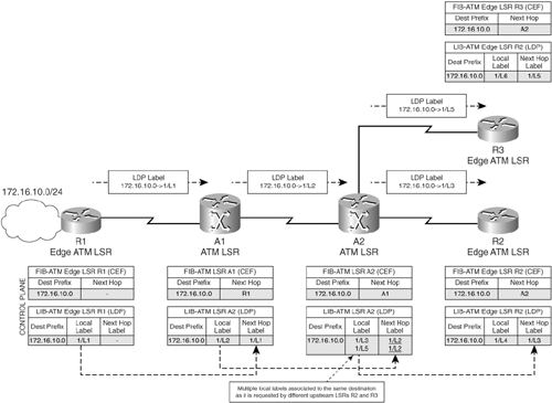
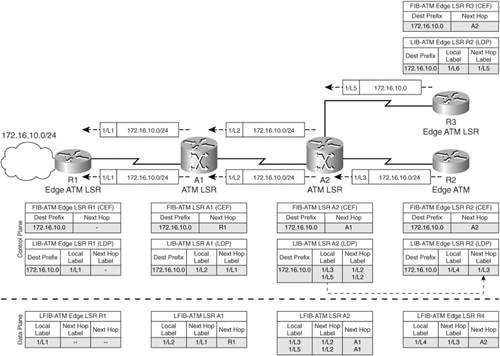
Figure 1-19 shows an ATM network with A1 and A2 being the ATM LSRs, and R1 and R2 are edge ATM LSRs. Network 172.16.10.0/24 is directly connected to R1.
Figure 1-19. Label Allocation and Distribution: Cell-Mode MPLS
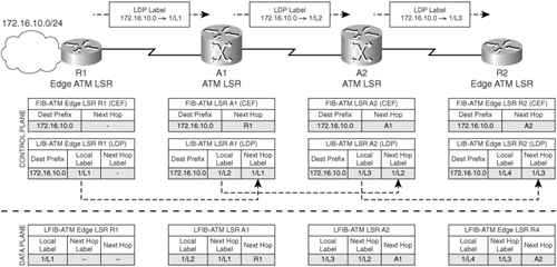
The process of label allocation and distribution is the same as frame-mode MPLS in cell-mode MPLS operation. The downstream ATM Edge LSR R1 allocates a local label for network 172.16.10.0 and propagates the same upstream. This process is repeated on the ATM LSRs A1 and A2. The only difference between cell-mode and frame-mode MPLS are that no penultimate hop popping occurs at the penultimate hop ATM LSR, and the labels assigned are the VPI/VCI values copied from the ATM header. In addition to the previously mentioned differences, cell-mode MPLS uses an interface level label space versus frame mode that can either use an interface level or router level label space.
Assuming that the VPI assigned to all virtual circuits (and thus the label VPI values) on R1, R2, A1, and A2 is 1, and L1, L2, L3, and L4 are the respective VCIs associated with R1, A1, A2, and R2, the FIB, LIB, and LFIB values on the ATM LSRs and the Edge ATM LSRs are as depicted in Figure 1-19.
Data plane operation in the cell-mode MPLS network is as follows:
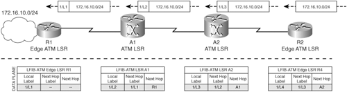
- When a data packet destined for network 172.16.10.0/24 is received on R2, it imposes an outgoing label of 1/L3 and forwards the same to downstream ATM LSR A2.
- LSR A2 does an LFIB lookup and replaces the top label of 1/L3 with next-hop label of 1/L2 and forwards the cells to ATM LSR A1.
- LSR A1 also performs an LFIB lookup and replaces the top label with next-hop label of 1/L1 and forwards the cells to ATM Edge LSR R1. Note that unlike frame-mode MPLS, the penultimate hop LSR does not pop the top label prior to forwarding to the Edge LSR in a cell-mode MPLS implementation. Therefore, upon receiving the cells, Edge ATM LSR pops the label and performs a lookup to identify the path to the destination network 172.16.10.0/24, which is directly connected.
The data plane forwarding operation in cell-mode MPLS is depicted in Figure 1-20.
Figure 1-20. Data Plane Operation: Cell-Mode MPLS
Loop Detection in Cell-Mode MPLS
In cell-mode MPLS, the ATM header does not posses a TTL field such as in the IP header or in a label when implementing frame-mode MPLS to enable loop detection by the use of TTL values in the header. The label distribution protocol used in the control plane for label allocation and distribution relies on the Layer 3 protocols to primarily perform the functions of loop detection.
LDP contains two mechanisms to enable loop detection in cell-mode MPLS. As previously mentioned, LDP sends messages in the form of TLVs. Two such TLVs are used in cell-mode MPLS to enable loop detection in cell-mode MPLS. This is also often called loop detection using path vectors (RFC 3035). Figure 1-21 depicts the LDP message format with the LDP PDU header consisting of the version, PDU length, and LDP identifier fields, as well as the LDP message. As shown in Figure 1-21, the LDP message type consists of the U bit, F bit, message type, length, and value.
Figure 1-21. LDP PDU and Message Format
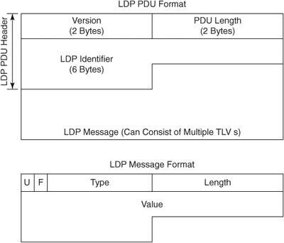
The U bit or the unknown TLV bit if set (=1) is ignored and the rest of the message is processed. If the U bit is unset (=0), the message is ignored, and a notification (error report) is sent to the source.
The F bit or forward unknown TLV bit is applicable only when the U bit is set (=1) and the LDP message containing the unknown TLV is to be forwarded. If the message with the U-bit set is received and the F bit is set, the message is forwarded.
Type identifies how the value field is to be interpreted. In the cell-mode MPLS implementation, the type field can identify a hop-count or a path vector for loop detection.
Length identifies the length of the value field in octets.
Value is an octet string defining the value for the type field.
In cell-mode MPLS loop detection, the first TLV that is used is called the hop count TLV, which is propagated during label distribution along with the specific destination prefix. The hop count TLV format and implementation is depicted in Figure 1-22.
Figure 1-22. Hop Count TLV Implementation in Cell-Mode MPLS
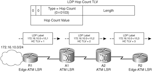
In Figure 1-22, the format of the hop count TLV and its implementation are depicted. The hop count TLV is an optional message during LSP setup between LSRs. The function of the hop count TLV is to calculate the number of LSR hops along an LSP during setup. In the network in Figure 1-22, Router R1 advertises the local label to reach the destination prefix 172.16.1.0 with a hop count TLV of 1. Upon receiving this label, the ATM LSR A1 advertises its local label L2 to upstream LSR A2 after incrementing the hop count TLV value to 2. This process is repeated in LSR A2 whereby the LSR advertises its local label to upstream edge ATM LSR R2 with a hop count TLV value of 3. Therefore, Edge ATM LSR R2 now knows that the number of hops to reach network 172.16.1.0/24 is 3.
The second loop detection mechanism employed in cell-mode MPLS is with the use of the path vector TLV. For readers familiar with BGP, the path vector TLV is similar to the use of AS path processing in BGP where the update is rejected if an AS in the AS-Path attribute is the same as the receiver's AS number. The path vector TLV is used to prevent LDP request message loops in the cell-mode domain. The path vector TLV contains a list of router IDs of routers that the update or the request has traversed. So, if you receive an update or a request with your own router ID in the path vector TLV, the request, of course, is ignored. Figure 1-23 depicts the path vector TLV message format and its operation.
Figure 1-23. Path Vector TLV Message Format and Operation
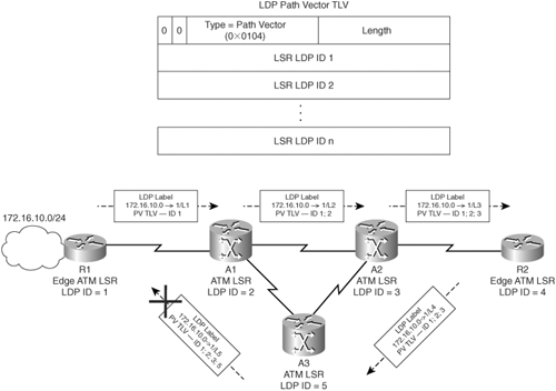
In Figure 1-23, the LSR LDP IDs are simplified to be 1, 2, 3, 4, and 5 for R1, A1, A2, R2, and A5. The Edge ATM LSR R1 places its LSR LDP ID (ID=1) in the path vector TLV value and forwards the advertisement upstream to ATM LSR A1 during the LDP message exchange for FEC 172.16.10.0/24. A1 appends its LSR LDP ID (ID=2) in the path vector TLV value field and forwards the same upstream to A2. (Forwarding of label mapping to A3 is not depicted for simplicity.) A2 appends its LDP ID (ID=3) to the path vector TLV message and forwards the same to LSR A3 and Edge ATM LSR R2. When A3 places its LDP ID in the path vector TLV and sends a label mapping for the FEC 172.16.10.0/24 back to A1, A1 detects its own LDP ID in the path vector TLV and thus rejects this update/label mapping for the FEC, thus avoiding loops. In cell-mode MPLS, no TTL is implemented to prevent indefinite routing loops, but the hop count TLV sets the maximum number of hops, and the path vector TLV is implemented to prevent actual loops in LDP.
ATM VC-Merge
In cell-mode MPLS, a single label is maintained per destination for each upstream LSR requesting the information. This leads to an increase in the number of labels that are maintained in the core ATM LSRs when a large number of Edge ATM LSRs are connected to the same ATM LSR. Certain optimization techniques can be employed that can reduce the number of labels that need to be maintained on a per LSR basis.
Virtual circuit merge (VC-merge) is the most common methodology employed in cell-mode MPLS that enables a fewer number of labels to be maintained per LSR. In VC-merge, an LSR maintains labels per destination and uses the same outgoing label for the same destination from different upstream LSRs. Figure 1-24 depicts the network in Figure 1-19 with an additional Edge ATM LSR R3 connected to ATM LSR A2. Without VC-merge enabled, A2 allocates two separate labels for the destination 172.16.1.0/24 and propagates them upstream to Edge ATM LSRs R2 and R3. R2 receives a next-hop label of 1/L3 and R3 receives a next-hop label of 1/L5 for the same destination.
Figure 1-24. Cell-Mode MPLS Without VC-Merge
However, with VC-merge enabled, Edge ATM LSRs R2 and R3 both receive the same label of 1/L3 as the next-hop label mapping to destination 172.16.1.0, which provides label space savings on the ATM LSRs, as shown in Figure 1-25.
Figure 1-25. Cell-Mode MPLS with VC-Merge

Cell Interleave with VC-Merge Implementation
After implementation of VC-merge on the ATM switches in the core, an issue arises: cell interleaving. With VC-merge, the same VC label is used for multiple upstream neighbors to send traffic to the same destination. If multiple upstream neighbors send traffic simultaneously to the same destination, the ATM LSR cannot guarantee that traffic from the two sources to the same destination will not be interleaved in transit as they use the same VC to the downstream neighbor toward destination.
Because the VC values are the same for all the cells, although the traffic is from two different sources, the downstream LSRs are incapable of identifying the correct source of the traffic. As shown in Figure 1-26, the ATM LSR A2 connected to multiple Edge LSRs R2 and R3 (as depicted in Figure 1-25) need to send a request for labels mapping to the same destination downstream and need to maintain multiple labels for each Edge LSR connected to the switch for each destination prefix.
Figure 1-26. Cell Interleave with VC-Merge
In some cases, the ATM switch is capable of buffering cells from a single source to a particular destination when traffic from another source to the same destination is transmitted downstream. The ATM switches buffer packets until they receive a cell with the end of frame bit set. The cells in the buffer are transmitted only if no traffic using the same VC to the destination is currently in transit from the ATM switch. Therefore, in this case, VC-merge is fully functional but introduces delays in transit as multiple sources are unable to send traffic to the same destination.
In the absence of buffering capabilities, the ATM LSR needs to have VC-merge disabled to avoid cell interleaving and associated issues.
MPLS Overview
- MPLS Overview
- Unicast IP Forwarding in Traditional IP Networks
- Overview of MPLS Forwarding
- MPLS Terminology
- MPLS Control and Data Plane Components
- MPLS Operation
- Special Outgoing Label Types
- Penultimate Hop Popping
- Frame-Mode MPLS
- Cell-Mode MPLS
Basic MPLS Configuration
- Basic MPLS Configuration
- Frame-Mode MPLS Configuration and Verification
- Cell-Mode MPLS over ATM Overview, Configuration, and Verification
- Command Reference
Basic MPLS VPN Overview and Configuration
- Basic MPLS VPN Overview and Configuration
- VPN Categories
- MPLS VPN Architecture and Terminology
- MPLS VPN Routing Model
- MPLS VPN Basic Configuration
- Outbound Route Filters
- Command Reference
PE-CE Routing Protocol-Static and RIP
- PE-CE Routing Protocol-Static and RIP
- Static PE-CE Routing Overview, Configuration, and Verification
- Static PE-CE Routing Command Reference
- RIPv2 PE-CE Routing Overview, Configuration, and Verification
- RIPv1 PE-CE Routing Configuration and Verification
- RIP PE-CE Routing Command Reference
PE-CE Routing Protocol-OSPF and EIGRP
- PE-CE Routing Protocol-OSPF and EIGRP
- OSPF PE-CE Routing Protocol Overview, Configuration and Verification
- EIGRP PE-CE Routing Protocol Overview, Configuration, and Verification
Implementing BGP in MPLS VPNs
- Implementing BGP in MPLS VPNs
- BGP PE-CE Routing Protocol Overview, Configuration, and Verification
- Implementing Route-Reflectors in MPLS VPN Networks
- Case Study-Hub and Spoke MPLS VPN Network Using BGP PE-CE Routing for Sites Using Unique AS Numbers
- Case Study-Hub and Spoke MPLS VPN Network with Sites Using Same AS Numbers
- Command Reference
Inter-Provider VPNs
- Inter-Provider VPNs
- Overview of Inter-Provider VPNs
- Option 1: Inter-Provider VPN Using Back-to-Back VRF Method
- Option 2: Inter-Provider VPNs Using ASBR-to-ASBR Approach
- Option 3: Multi-Hop MP-eBGP Between RR and eBGP Between ASBRs
- Option 4: Non-VPN Transit Provider
- Case Study-Inter-AS Implementing Route-Reflector and BGP Confederation in Provider Networks
- Case Study-Multi-Homed Inter-AS Provider Network
- Command Reference
Carrier Supporting Carriers
- Carrier Supporting Carriers
- Carrier Supporting Carriers Overview
- Deployment Scenarios with CSC Architecture
- CSC Architecture Benefits
- Command Reference
MPLS Traffic Engineering
- MPLS Traffic Engineering
- TE Basics
- MPLS TE Theory
- Constraint-Based Routing and Operation in MPLS TE
- Configuring MPLS TE
- Command Reference
Implementing VPNs with Layer 2 Tunneling Protocol Version 3
- Implementing VPNs with Layer 2 Tunneling Protocol Version 3
- L2TPv3 Overview
- Configuring L2TPv3 Tunnels for Layer 2 VPN
- Configuring L2TPv3 Static Tunnels
- Configuring L2TPv3 Dynamic Tunnels
- Implementing Layer 3 VPNs over L2TPv3 Tunnels
- Command Reference
Any Transport over MPLS (AToM)
- Any Transport over MPLS (AToM)
- Introduction to Layer 2 VPNs
- Implementing AToM for Like to Like Circuits
- L2 VPN-Any to Any Interworking
- Local Switching
- Command Reference
Virtual Private LAN Service (VPLS)
- Virtual Private LAN Service (VPLS)
- VPLS Overview
- VPLS Topology-Single PE or Direct Attachment
- Hierarchical VPLS-Distributed PE Architecture
- Command Reference
Implementing Quality of Service in MPLS Networks
- Implementing Quality of Service in MPLS Networks
- Introduction to QoS-Classification and Marking
- MPLS QoS Implementation
- MPLS QoS Operating Modes
- Modular QoS CLI: Configuration of QoS on Cisco Routers
- Configuration and Implementation of MPLS QoS in Uniform Mode and Short Pipe Mode Operation
- Implementing MPLS QoS for Layer 2 VPN Implementations
- Command Reference
MPLS Features and Case Studies
- MPLS Features and Case Studies
- Case Study 1: Implementing Multicast Support for MPLS VPNs
- Case Study 2: Implementing Multi-VRF CE, VRF Selection Using Source IP Address, VRF Selection Using Policy-Based Routing, NAT and HSRP Support in MPLS VPN, and Multicast VPN Support over Multi-VRF CE
- Case Study 3: Implementing Layer 2 VPNs over Inter-AS Topologies Using Layer 2 VPN Pseudo-Wire Switching
- Case Study 4: Implementing Layer 3 VPNs over Layer 2 VPN Topologies and Providing L2 VPN Redundancy
- Case Study 5: Implementing Dynamic Layer 3 VPNs Using mGRE Tunnels
- Case Study 6: Implementing Class-Based Tunnel Selection with MPLS Traffic Engineering
- Case Study 7: Implementing Hub and Spoke Topologies with OSPF
- Case Study 8: Implementing Hub and Spoke Topologies with EIGRP
- Case Study 9: Implementing VPLS Services with the GSR 12000 Series
- Case Study 10: BGP Site of Origin
- Command Reference
EAN: 2147483647
Pages: 130
