Introduction to QoS-Classification and Marking
In its simplistic form, QoS is the ability to differentiate diverse classes of traffic based on predefined or user-defined criteria and assign priorities based on traffic variables that affect the treatment of traffic on each router in the network. QoS, when implemented, becomes a requirement for end-to-end service delivery. In some cases, QoS might not be chosen for implementation in networks with excess bandwidth on links. However, it is recommended practice to implement QoS where different classes of traffic are to be transported across the SP network.
The first and foremost step in the deployment of QoS is to identify the various traffic classes that need to be supported by the network. Traffic can be classified based on type of traffic (voice, applications, data, etc.) and on properties of the traffic pattern. After traffic has been classified into different classes, the next step is to identify what QoS operations will be performed on each of these classes on the local router. Note that although QoS is an end-to-end implementation, it is traditionally configured on all routers in the path from one end to the other. However, various portions of the network can be configured with different QoS schemes to handle different types of traffic. The process of defining the QoS operations for a certain traffic class is also called Service Policy definition. Finally, after the policies are defined, they are applied on the device interface. Implementation of QoS, therefore, involves the following steps:
|
Step 1. |
Classification of traffic based on predefined or user-defined criteria |
|
Step 2. |
Configuration of device for QoS policies for each of the predefined or identified classes |
|
Step 3. |
Association of QoS policy/policies to an interface |
In the Diff-Serv model, the routers or L3 switches in the network are configured for QoS policies that can be applied to a traffic class traversing the router. Simplistically, traffic classes can be defined by the type of traffic, such as voice, video, and data. Data traffic can also be segregated into different traffic classes based on the type of data (application versus best effort) using QoS. This mechanism where the router classifies and then applies a QoS policy based on the classification is often called the Per-Hop-Behavior (PHB) of the router.
Classification and Marking
Classification is the first step in the implementation of QoS. The criteria used to classify data can be based on the IP header values such as the IP address ranges, IP Precedence, DSCP, CoS, or, more recently, MPLS EXP bits. In the classification stage, the router identifies traffic that will map to each of the classes to be configured.
Following classification, the router can also perform marking of packets that map to a certain class. In the marking action, the router associates the packet with a unique parameter after identification of traffic pertaining to a class. This unique parameter will be used in subsequent routers to identify or, in QoS terms, classify the traffic. The common marking options available on Cisco routers and switches are IP Precedence, DSCP, CoS, ToS bits, QoS group, and MPLS EXP values.
IP Precedence, DSCP, and ToS Relationships
Figure 13-1 shows the IPv4 packet header with an 8-bit type of service (ToS) field. The ToS field was conventionally used to provide QoS in IP networks. However, since the advent of the Diff-Serv model, it has been replaced by the implementation of IP Precedence or DSCP values.
Figure 13-1. IP Packet Header
The higher order 3 bits in the TOS field, shown in Figure 13-1, map to the IP Precedence value assigned to the IP packet. The predefined values used to identify the IP Precedence are shown in Table 13-1.
|
IP Precedence Value |
Binary Value |
Priority |
|---|---|---|
|
0 |
000 |
Routine |
|
1 |
001 |
Priority |
|
2 |
010 |
Immediate |
|
3 |
011 |
Flash |
|
4 |
100 |
Flash Override |
|
5 |
101 |
Critical |
|
6 |
110 |
Internetwork Control |
|
7 |
111 |
Network Control |
The most important values for IP Precedence in the implementation of QoS are the Critical, Flash Overrides, and Flash priorities. It is common practice to implement an IP Precedence of Critical (5) for VoIP traffic or time-sensitive/real-time traffic, Flash override (4) for video traffic, and Flash (3) for higher class data traffic. All other traffic is usually mapped into best-effort or routine (0) traffic.
DSCP, as shown in Figure 13-1, is an extension of IP Precedence and can be still coded in context to the ToS value in an IP header. The DSCP value is the IP Precedence implemented along with a Delay, Throughput, and Reliability variable. DSCP is 6 bits in length and functions as the higher order 6 bits of the ToS byte. Therefore, the higher order 3 bits of the ToS byte as well as DSCP map to IP Precedence. In the implementation of DSCP, the delay and throughput variables collectively are called the drop probability. The reliability bit is not used in DSCP implementations today and is usually set to a value of 0. The most common values of DSCP that you will implement are the expedited forwarding (EF) as well as the assured forwarding (AF) classes.
The drop probability bits can be set to three values, as shown in Table 13-2: low drop (01), medium drop (10), or high drop (11).
|
Drop Probability |
Value |
|---|---|
|
Low drop |
01 |
|
Medium drop |
10 |
|
High drop |
11 |
DSCP accommodates additional granularity by implementation of 6 bits versus 3 in IP Precedence and ToS. As shown in Figure 13-2, the EF class directly maps to the IP Precedence value of 5, which is used for real-time traffic patterns. Figure 13-2 also shows the AF class where the IP Precedence value of 4 is used as the top-most 3 bits of the AF class. Further granularity is provided by classification of the traffic as either low drop (AF41), medium drop (AF42), or high drop (AF43) within the AF class.
Figure 13-2. DSCP Classes
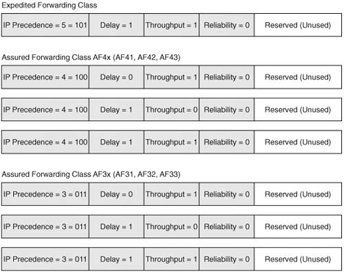
The AF classes for IP Precedence 2 and 1 can be derived by replacing the IP Precedence bits with 010 or 001, respectively. (For brevity, Figure 13-2 does not depict this).
MPLS EXP Bit Marking
When traversing from an IP domain to an MPLS domain, IP QoS can be mapped to MPLS QoS using the MPLS EXP bits in the MPLS labels. As mentioned in Chapter 1, "MPLS Overview," the 3 bits map one-to-one with IP Precedence values. Therefore, when transitioning an IP domain containing DSCP markings versus IP Precedence markings, if more than one DSCP value is used per AF class, care must be taken to preserve granularity of the IP QoS as it traverses the MPLS domain because more than one AF subclass (for example, AF41, AF42) might map to the same MPLS EXP bit marking. The format of the MPLS label has been depicted in Figure 13-3.
Figure 13-3. MPLS Label Format
It is important to note that in the implementation of label stacks, matching of data pertaining to a premarked MPLS EXP value can be done only on the top label in the label stack. You will be provided with more information in the following sections on how label stacks and QoS implementations work in tandem.
Congestion Management, Congestion Avoidance, Traffic Shaping, and Policing
When implementing QoS, a common term used is queuing. Cisco offers a variety of queuing strategies that manage resources where congestion might occur. In traditional networks, the transition from a LAN (10/100/1000 Mbps) to a WAN (T1/T3/OC-x) makes the gateway in between a congestion point. In such cases, queuing might be configured on the gateway at the network edge where the enterprise network connects to the SP network for intersite or Internet connectivity.
Congestion management is the process of selectively queuing packets on routers so that the higher priority packets associated to a class are transmitted first during congestion. It is assumed that the reader understands various queuing strategies such as priority queuing (PQ), custom queuing (CQ), weighted fair queuing (WFQ), class-based weighted fair queuing (CBWFQ), low latency queuing (LLQ), and modified and weighted deficit round robin (only on Cisco 12000 series). Coverage of the nuances of these queuing strategies is beyond the scope of this book. For more information on these queuing strategies, visit the Cisco Systems website at Cisco.com.
Congestion avoidance is the process of selectively dropping packets prior to the queues reaching 100% of their maximum queue depth, at which time all subsequent packets are dropped. This process of dropping all packets when the queue is full is called tail-drop. Within each queue, depending on the queuing strategy, a minimum and maximum threshold can be configured so that, between these thresholds, the packets are dropped at increasing probability. The mechanism used for congestion avoidance is called Weighted Random Early Detection (WRED), which to a large extent overcomes tail-drop issues per queue on a router. When queuing is performed on a router interface, tail-drop occurs per queue in the absence of random early detection. With random early detection, the queue never reaches 100 percent of its depth and, therefore, no tail-dropping of packets occurs. Different WRED probabilities can also be associated to various queues on a per interface basis that enables differential dropping of packets per class associated with a certain queue.
The process of enforcing a policy by discarding packets in accordance to a traffic profile associated with a class is done using policing and/or shaping. In its most generic form, policing and shaping are alike except that policing drops all packets that do not conform to a policy whereas shaping buffers packets that do not conform to a QoS policy. Therefore, policing is an aggressive procedure where all packets that exceed a certain bandwidth limitation are dropped.
The following congestion management and avoidance schemes can be used in conjunction with MPLS:
- FIFO – Congestion management
- Modified deficit round robin on GSR 12000 series – Congestion management
- CBWFQ with LLQ – Congestion management
- WRED – Congestion avoidance
- Traffic shaping and policing
In summary, the QoS mechanisms that are performed on a packet, also called the PHB or per-hop behavior, can consist of the following functions:
- Classification
- Marking
- Congestion management – Queuing
- Congestion avoidance – Selective dropping
- Traffic policing and shaping
Figure 13-4 outlines these QoS functions and how they can be implemented on a router.
Figure 13-4. QoS Mechanisms
As shown in Figure 13-4, classification and marking are traditionally performed on ingress. In some cases, classification can also be done on egress. Congestion management, avoidance, and traffic shaping and policing are usually performed on egress. Note that policing can also be performed on ingress, but shaping cannot be implemented on ingress.
MPLS Overview
- MPLS Overview
- Unicast IP Forwarding in Traditional IP Networks
- Overview of MPLS Forwarding
- MPLS Terminology
- MPLS Control and Data Plane Components
- MPLS Operation
- Special Outgoing Label Types
- Penultimate Hop Popping
- Frame-Mode MPLS
- Cell-Mode MPLS
Basic MPLS Configuration
- Basic MPLS Configuration
- Frame-Mode MPLS Configuration and Verification
- Cell-Mode MPLS over ATM Overview, Configuration, and Verification
- Command Reference
Basic MPLS VPN Overview and Configuration
- Basic MPLS VPN Overview and Configuration
- VPN Categories
- MPLS VPN Architecture and Terminology
- MPLS VPN Routing Model
- MPLS VPN Basic Configuration
- Outbound Route Filters
- Command Reference
PE-CE Routing Protocol-Static and RIP
- PE-CE Routing Protocol-Static and RIP
- Static PE-CE Routing Overview, Configuration, and Verification
- Static PE-CE Routing Command Reference
- RIPv2 PE-CE Routing Overview, Configuration, and Verification
- RIPv1 PE-CE Routing Configuration and Verification
- RIP PE-CE Routing Command Reference
PE-CE Routing Protocol-OSPF and EIGRP
- PE-CE Routing Protocol-OSPF and EIGRP
- OSPF PE-CE Routing Protocol Overview, Configuration and Verification
- EIGRP PE-CE Routing Protocol Overview, Configuration, and Verification
Implementing BGP in MPLS VPNs
- Implementing BGP in MPLS VPNs
- BGP PE-CE Routing Protocol Overview, Configuration, and Verification
- Implementing Route-Reflectors in MPLS VPN Networks
- Case Study-Hub and Spoke MPLS VPN Network Using BGP PE-CE Routing for Sites Using Unique AS Numbers
- Case Study-Hub and Spoke MPLS VPN Network with Sites Using Same AS Numbers
- Command Reference
Inter-Provider VPNs
- Inter-Provider VPNs
- Overview of Inter-Provider VPNs
- Option 1: Inter-Provider VPN Using Back-to-Back VRF Method
- Option 2: Inter-Provider VPNs Using ASBR-to-ASBR Approach
- Option 3: Multi-Hop MP-eBGP Between RR and eBGP Between ASBRs
- Option 4: Non-VPN Transit Provider
- Case Study-Inter-AS Implementing Route-Reflector and BGP Confederation in Provider Networks
- Case Study-Multi-Homed Inter-AS Provider Network
- Command Reference
Carrier Supporting Carriers
- Carrier Supporting Carriers
- Carrier Supporting Carriers Overview
- Deployment Scenarios with CSC Architecture
- CSC Architecture Benefits
- Command Reference
MPLS Traffic Engineering
- MPLS Traffic Engineering
- TE Basics
- MPLS TE Theory
- Constraint-Based Routing and Operation in MPLS TE
- Configuring MPLS TE
- Command Reference
Implementing VPNs with Layer 2 Tunneling Protocol Version 3
- Implementing VPNs with Layer 2 Tunneling Protocol Version 3
- L2TPv3 Overview
- Configuring L2TPv3 Tunnels for Layer 2 VPN
- Configuring L2TPv3 Static Tunnels
- Configuring L2TPv3 Dynamic Tunnels
- Implementing Layer 3 VPNs over L2TPv3 Tunnels
- Command Reference
Any Transport over MPLS (AToM)
- Any Transport over MPLS (AToM)
- Introduction to Layer 2 VPNs
- Implementing AToM for Like to Like Circuits
- L2 VPN-Any to Any Interworking
- Local Switching
- Command Reference
Virtual Private LAN Service (VPLS)
- Virtual Private LAN Service (VPLS)
- VPLS Overview
- VPLS Topology-Single PE or Direct Attachment
- Hierarchical VPLS-Distributed PE Architecture
- Command Reference
Implementing Quality of Service in MPLS Networks
- Implementing Quality of Service in MPLS Networks
- Introduction to QoS-Classification and Marking
- MPLS QoS Implementation
- MPLS QoS Operating Modes
- Modular QoS CLI: Configuration of QoS on Cisco Routers
- Configuration and Implementation of MPLS QoS in Uniform Mode and Short Pipe Mode Operation
- Implementing MPLS QoS for Layer 2 VPN Implementations
- Command Reference
MPLS Features and Case Studies
- MPLS Features and Case Studies
- Case Study 1: Implementing Multicast Support for MPLS VPNs
- Case Study 2: Implementing Multi-VRF CE, VRF Selection Using Source IP Address, VRF Selection Using Policy-Based Routing, NAT and HSRP Support in MPLS VPN, and Multicast VPN Support over Multi-VRF CE
- Case Study 3: Implementing Layer 2 VPNs over Inter-AS Topologies Using Layer 2 VPN Pseudo-Wire Switching
- Case Study 4: Implementing Layer 3 VPNs over Layer 2 VPN Topologies and Providing L2 VPN Redundancy
- Case Study 5: Implementing Dynamic Layer 3 VPNs Using mGRE Tunnels
- Case Study 6: Implementing Class-Based Tunnel Selection with MPLS Traffic Engineering
- Case Study 7: Implementing Hub and Spoke Topologies with OSPF
- Case Study 8: Implementing Hub and Spoke Topologies with EIGRP
- Case Study 9: Implementing VPLS Services with the GSR 12000 Series
- Case Study 10: BGP Site of Origin
- Command Reference
EAN: 2147483647
Pages: 130
