Configuring, Manipulating, and Reusing ORM Models
Configuring ORM Preferences
When you first work with the ORM modeling solution, the tool applies various default settings to determine how it displays the user interface, and how it reacts to certain user commands. You can change these settings to better suit your personal preferences by entering your choices in the Database Modeling Preferences dialog.
To access this dialog, choose Database > Options > Modeling from the main menu. The dialog includes Fact Editor and ORM Diagram panes for setting ORM preferences. The other two panes deal with preferences for the logical modeling solution, and are covered in a later chapter.
Figure 6-1 shows the Fact Editor pane of the dialog with the category set to Input preferences. Use this to choose Guided or Freeform entry, decide whether to combine "at most one" and "some" as "exactly one" in constraints, and use capitals or brackets to distinguish object types. These options were explained in sections 4.2 and 4.3.
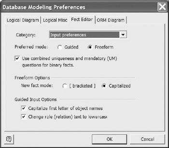
Figure 6-1: Configuring input preferences for the Fact Editor.
Use the Category list-box in the Fact Editor pane to select the Miscellaneous preferences and Syntax Colors options displayed in Figure 6-2. These options should be selfexplanatory. For further details on any of these options, select the option, then press the F1 key to display the context-sensitive help.
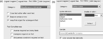
Figure 6-2: Configuring other Fact Editor preferences.
Select the ORM Diagram tab of the Database Modeling Preferences dialog to display the ORM Diagram pane shown in Figure 6-3. By default, the option for When removing an object from a diagram is set to "Ask user what to do." This ensures that if you press the Delete key when one or more model elements are selected, you are prompted whether to delete them from the diagram only or from the model as well. This prompt can save you from an accidental deletion, so don't change this default setting unless you have good reason to do so.
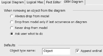
Figure 6-3: Configuring ORM diagram preferences.
The Object type name field allows you to control the base default name for new object types. By default, this is "Object." The Append ordinal check box is used to append numbers 2, 3, etc., to the default names of second and later object types. So unless you choose otherwise , new object types are named "Object," "Object2," etc., until you rename them. To view this behavior, drag the Object Type shape from the ORM stencil multiple times onto the drawing window.
Showing Relationships for Object Types
In an ORM schema, object types may be connected by predicates and/or subtype relationships. Graphically, a predicate is depicted as a named sequence of one or more role boxes, and a subtype relationship is depicted as an arrow from subtype to supertype . To understand the impact of a given object type within a model, it is extremely useful to view all of its connections to the rest of the schema.
Although you can use the Business Rules window to drag all of an object type's fact types onto the drawing window, this can be tedious since you need to search for all the fact types that include the object type at any position in the predicate (start, middle, or end). Moreover, the Business Rules window does not include the subtype connections for the object type. Fortunately, the context menu of an object type includes a Show Relationships operation that let's you display all of its connections in one go. Applying this operation to an object type displays all of the fact types and subtype relationships in which it participates.
The best way to understand this operation is to watch it in action. Let's see how it works using the Patient CS model. Open this model, and then insert a new page by selecting Insert > New Page from the main menu. If the Page Setup dialog appears, press the OK button to accept the default settings. The drawing window now displays a new, blank page. Open the Object Types pane of the Business Rules window, and drag FemalePatient onto the drawing surface. Now right-click this shape to display its context menu, and select Show Relationships , as shown in Figure 6-4.
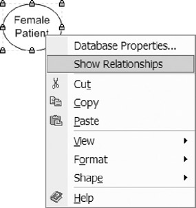
Figure 6-4: Right-click an object type to access its context menu.
This results in the display shown in Figure 6-5. In the global schema, FemalePatient participates in the two fact types shown and in a subtype relationship to Patient.
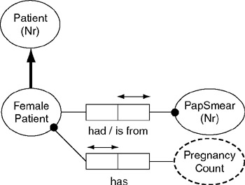
Figure 6-5: The display after applying Show Relationships to FemalePatient.
Now right-click the PapSmear object type, and choose Show Relationships from its context menu. This adds to the display all the other connections for PapSmear. This results in two more fact types being displayed, as shown in Figure 6-6.
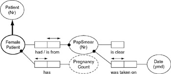
Figure 6-6: The display on applying Show Relationships to PapSmear in Figure 6-5.
Using the Show Relationships feature, you can progressively open up a model, expanding the neighborhood displayed for any object type you choose. This is very useful for model browsing, and for deciding what the impact would be of removing an object type from the model. As we'll see in a later chapter, it is also extremely useful for displaying an ORM model that has been reverse-engineered from an existing database.
Redisplaying Model Elements
Each model element such as an object type or predicate occurs only once in the underlying model. However, you can display as many copies as you like of the same model element on the diagram, on the same page or on different pages.
One reason to display multiple copies of a model element on the same page is to provide a cleaner layout by avoiding line crossings. This is especially true if your model includes object types like Date and MoneyAmount, which often play lots of roles. For example, the diagram for the insurance model fragment shown in Figure 6-7 is untidy because the role connector from Date to the birthdate role crosses over the branch location fact type.
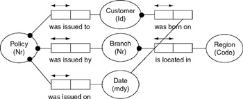
Figure 6-7: This diagram is untidy because of edge crossings.
One solution to this problem is to place another copy of the Date object type on the diagram, and connect the birthdate role to it, as shown in Figure 6-8. The easiest way to copy a diagram instance of a model element is to Control-drag it to another place on the diagram. To do this, select the element shape, then hold the Ctrl key down as you drag a copy of it to the new position using the mouse. In this example, we also need to reposition the role connector. To do this, select the role (two mouse clicks) then drag the end of its connector (displayed as a small, red diamond) and glue it to the desired copy of the object type shape.
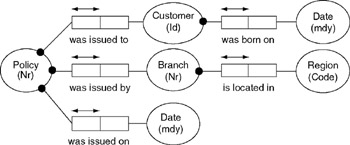
Figure 6-8: An extra copy of Date is used to avoid edge crossings.
Although the diagram displays two different copies of the Date object type, both copies denote the same underlying object type in the model. If you make a change to one (e.g. change its name or data type) this change is immediately reflected in the other copy.
An alternative way to redisplay an object type or a fact type is to drag it onto the page from the Business Rules window . This is also the only way to display an object type or fact type on a page where no instance of it is yet displayed.
If the object types in a subtype- supertype relationship have been redisplayed without the relationship itself, you can now redisplay the relationship as well by selecting the arrow and control-dragging it to connect to the object types.
More than one model element can be redisplayed at once. So long as you stay on the same page, you can select all or part of the model displayed on that page, and redisplay the selection by controlling-dragging it to another position on the page.
Cloning Model Elements
It is also possible to clone a model element . Cloning creates a new model element (not just a shape) based on an existing one. When created, the clone has the same model properties as the original, except for the name . To clone a model element that is displayed on a diagram page, select the element, press Ctrl+C to copy it to the clipboard, then move the mouse cursor to the position (on the same page or a different page) where you wish to display the clone, and press Ctrl+V to paste the clone there. Instead of Ctrl+C, you can use the main menu option Edit > Copy . Instead of Ctrl+V, you can use the menu option Edit > Paste .
Each clone of an object type is assigned the name of its source, appended by a number that indicates the order in which it has been cloned from the original. For example, if you copy the Date object type to the clipboard and paste it, this results in the clone Date1. If you now copy the Date1 object type to the clipboard and paste it, this results in the clone Date11. If instead you copy the Date object type to the clipboard and paste it twice, this results in the clones Date1 and Date2. Any cloned predicate is assigned the name of its original predicate, with no additional number. Within the same model or namespace, each object type must have a different name, but different predicates may have the same name.
A clone initially has the same model properties as the original, except for its name. If you later make a change to the original (e.g., modify its data type), this change is not propagated to the clone. Similarly, if you later make a change to the clone, this change is not propagated to the original. This is because the original and the clone correspond to different underlying model elements.
You can clone all or part of the model displayed on a page by selecting the relevant model elements, copying the selecting to the clipboard (Ctrl+C) and then pasting the cloned selection to the new position (Ctrl+V). For example, if you select the fact type Customer was born on Date , and then copy and paste it, this results in the clone fact type Customer1 was born on Date1 , as shown in Figure 6-9. As you can confirm by looking in the Business Rules window, these are two different fact types. Collectively, they include four different object types (Customer, Customer1, Date, Date1) and two different predicates that just happen to have the same name "was born on."
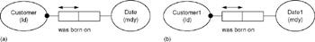
Figure 6-9: Fact type (a) is copied and pasted to produce the clone (b).
Cloning within the same model can speed up the process of adding new elements that have similar properties to existing ones. However, the most useful application of this copy-paste technique is to clone all or part of a model into another source model . For example, if you select and copy the model shown in Figure 6-8 to the clipboard, you can then open a new ORM source model and paste the clone into that. In this case, the diagram of the cloned model looks identical to the original model, with the names unchanged. Numbers are not appended to object type names in the new model, because the cloned model is already distinguished from its source by being in a different document. This cloning feature is extremely powerful, allowing you to duplicate whole models very quickly.
For documentation purposes, you can also copy and paste any selection from a model diagram into a word-processing document or a slide-presentation document for display there. For example, to copy an ORM diagram into Microsoft Word, select and copy the diagram to the clipboard, open a Word document, choose Edit > Paste Special from its main menu, and then choose the desired Paste option (the Picture option is usually best for copying just the diagram). See Chapter 9 for further details on model reporting and documentation.
Cutting and Pasting Model Elements
Although it is possible to cut and paste model elements, this procedure has limited use, and needs to be handled with care. To cut one or more model elements to the clipboard, first select the relevant model elements on the diagram surface, and then press Ctrl+X or choose Edit > Cut from the main menu. To paste this selection from the clipboard onto a drawing page, move the mouse cursor to the desired position and then press Ctrl+V or choose Edit > Paste from the main menu.
Cutting and pasting a model element selection to another position on the same or a different page moves the display of those model elements to the new position. However, any connections that the model elements had with the rest of the model will be lost . For example, Figure 6-10 shows the effect of cutting the Patient object type from the first page of the Patient model. The six fact types in which Patient played on this page are now incomplete. Even if you pasted Patient back onto this page, it would have no connection to these fact types. You would need to re-establish the connections yourself by gluing the dangling role connectors to it. Moreover, all the connections that Patient had on other pages of the model would also be lost.
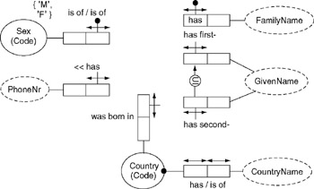
Figure 6-10: Cutting the Patient object type from the Patient model.
Essentially, the cut operation deletes the selection from the underlying model (not just the diagram). Although the model element selection on the clipboard is kept intact, it no longer has any semantic connection to the model. When you later paste that selection onto the diagram, you must re-declare any connections that you wish it to have with the rest of the model. This can be a lot of work, especially for model elements that were displayed more than once (on the same page or on multiple pages), since all those connections need to be redrawn. For such reasons, you will probably find little use for cutting and pasting model elements.
If you really want to move an object type or fact type from one page to another, drag a copy of it from the Business Rules window onto the other page, then select it on the original page, press the Delete key and answer No when prompted whether to delete it from the model.
If the whole model is displayed on a single page, and no element is displayed on another page, you can select the whole diagram then cut and paste it safely to a new page. However you can achieve the same effect simply by renaming and reordering pages. Our advice is to ignore the cut operation entirely when working with models.
Referencing Model Elements
Each object type is either an entity type or a value type, and is defined in exactly one model. Each predicate is also defined in exactly one model. It is possible however to define an object type or predicate in one model, and then reference it from one or more other models. In this case, the object type or predicate is said to be external to the referencing model(s).
For example, suppose the schema in Figure 6-11 is our preferred way to model states and countries . Here a country is primarily identified by a code (e.g., ˜US ) but also has a unique name (e.g., ˜United States of America ). A state is primarily identified by combining its country with its state code, but also has a unique name within its country. For example, Washington State is identified by the country code, state code combination ˜US , ˜WA , and West Australia is identified using the code combination ˜AU , ˜WA . Suppose we save this model using the name StateCountry_CS.
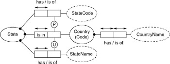
Figure 6-11: A standard model for States and Countries.
Now suppose the simple schema at the top of Figure 6-12 is another ORM source model named Invoice_CS. This schema references an object type named State, which has been declared external by checking the External check box in the definition pane of its Database Properties window, as shown. Object types that are external to a model are displayed in that model with a shaded fill pattern, and with no identification scheme.
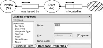
Figure 6-12: State is declared to be an external object type for the Invoice model.
In the model where they are defined, external object types are displayed as normal object types, along with their identification scheme, since they are internal to that model. Although the Invoice schema in Figure 6-12 declares State as an external object type, there is so far no connection between this and the State object type defined in the schema of Figure 6-11. It is possible that we might define a State object type in many models, and the system has no way of knowing at this stage which definition is intended for the Invoice schema.
To make the connection, both models must be included in the same database model project . Chapter 3 provided an introduction to project building, and Chapter 7 discusses this process in more detail. If you create a project that includes both the StateCountry_CS and Invoice_CS source models, the system automatically merges these models into a single, global model, matching the name of each object type that has been declared external to one model with the name of an object type defined in another model.
Once this resolution has taken place, each external object type is effectively replaced by a pointer to its definition in the other source model. Hence, if at any time later the definition of the external object type is changed in the model that defines it, this change is immediately reflected in the source model that references it. To propagate this change to a logical database model already built from the source model, you still need to rebuild the project.
When you try to build a project, if no match is found for an external object type, an error message notes that the object type is undefined . Right-click the error message to highlight the undefined external object type, and then take appropriate action to ensure it is defined in another source model for that project.
If more than one match is found for an external object type, an error message reports that the object type has more than one definition. You can then rename all but one of the candidate defining object types to ensure only one match is made. If you really do want more than one object type with the same name in the global model, you can add a different namespace for each candidate defining object type except the one you want to match up with.
Adding multiple ORM source models to the same project effectively forms the union of these source models, matching external and internal object types by name. When you build the project, this union is then mapped to a logical database schema. For example, a project formed by adding StateCountry_CS and Invoice_CS includes all the fact types from both.
To reuse just part of StateCountry_CS (e.g., just the primary reference scheme for State), you could include that subschema in Invoice_CS by cloning (copy-pasting) it from StateCountry_CS, rather than using an external object type. Of course, if you ever change the definition later in the StateCountry_CS model, this won't propagate automatically to your Invoice_CS model.
Predicates may be referenced in a similar way to object types. For example, the expanded Invoice model in Figure 6-13 references two external object types (State and Country) as well as the external predicate contained in the fact type State is in Country . This predicate has been declared external by checking the External check box in the definition pane of its Database Properties window, as shown. Predicates that are external to a model are displayed in that model without any constraints (since these are declared in their defining model). Unlike external object types, external predicates are displayed with no special fill pattern.
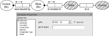
Figure 6-13: The predicate in State is in Country is declared as external.
A predicate reference is resolved when its model is merged with its defining model during a project build. Note that predicates are not distinguished simply by their name (e.g., "is in"). For example, the defining model could have many predicates with the local reading "is in," but it will have only one sentence type with the reading "State is in Country," and the references for State and Country are already disambiguated as discussed earlier. Because a predicate's sentence type provides its context, you should never need to make a name space entry to disambiguate a predicate reference.
As you can see, there are a number of ways in which you can reuse model components within other models. If you are building many models for a particular domain, it is often worthwhile to identify model fragments that are likely to be reused in different models, and save these fragments either as separate models that can be added into other projects, or as parts of a standard reference model where they can be selectively cloned into other models. In deciding which technique to apply, consider the impact of later changes to the original definition. Merging takes care of such changes automatically at the source model level, but cloning does not.
Overview of Database Modeling and the Database Modeling Tool
The Conceptual Modeling Solution (ORM)
- Object Types, Predicates, and Basic Constraints
- ORM Constraints
- Configuring, Manipulating, and Reusing ORM Models
- Mapping ORM Models to Logical Database Models
- Reverse Engineering and Importing to ORM
- Conceptual Model Reports
The Logical Modeling Solution (ER and Relational)
- Creating a Basic Logical Database Model
- Generating a Physical Database Schema
- Editing Logical Models”Intermediate Aspects
- Editing Logical Models”Advanced Aspects
- Reverse Engineering Physical Schemas to Logical Models
- Logical Database Model Reports
Managing Database Projects
EAN: 2147483647
Pages: 150
