Crash Course in the Internet Protocol Suite
Overview
As a consequence of the Internet’s explosion of popularity, most networking protocols that competed with IP, the Internet Protocol, have been relegated to niche status, or have been made to work with IP (such as NBT, which is NetBIOS running under TCP, the Transmission Control Protocol). The IP family of protocols has been designed to provide a range of services, from low-level networking functions that touch the hardware, through data routing, reliability, and scaling capabilities, to application-level transparency in a layered approach.
As this book is focused on intrusion detection, we will, in later chapters, examine the security implications of both the lower-level communication protocols and the applications that depend on them. For now, it is important to take note of the trust relationships between the various components. Unfortunately IPv4, the current version of the Internet Protocol in use today, was designed with scant attention to security. Many of the mechanisms implicitly trust the information that they receive from others, permitting the possibility of subversion by malicious parties. Depending on the protocol involved, misleading information may be supplied to trusting hosts, which could allow for intrusion into those hosts.
Conceptually, the various functions that network hardware and software must perform can be understood as a series of layers of functionality, with each layer built on and depending on the proper functioning of the layers below it. Each additional layer brings greater functionality and a higher level of abstraction. This layered approach also gives applications a great deal of independence, because they do not need to be concerned with implementation details.
The Open Systems Interconnection (OSI) reference model describes such a framework for understanding these layers. It was originally developed to guide the implementation of the OSI network suite (of which some implementations have been developed), but due to the overwhelming success of TCP/IP, its main use currently is as an educational tool.
An Introduction to the Seven Layer OSIReference Model
The OSI reference model is a conceptual model that provides a framework for specifying and identifying the various network functions. There are seven layers within the OSI model that serve to differentiate the various hardware and software functions that a network provides. Each layer depends on the proper functioning of the layer immediately below it to provide its raw functionality, which is enhanced and then passed to the next higher layer. Status messages may be communicated up or down the various layers, although each layer only communicates with its immediate neighbors. As each layer is solely dependent on the layer below it for lower-level services, higher layers are shielded from system, hardware, and software implementation details. This leads to independence from specific systems and interoperability with many vendors’ offerings.
The OSI model is very useful for developing and understanding a “big picture” view of network processes because it provides this independence. However, the model does not claim to exactly match any specific network technology. Each layer must encapsulate the data it receives into a standard format for the next higher layer, thus incurring an overhead, and in the name of efficiency, the lines between one or more layers can be blurred. Some layers may not specifically have counterparts in an actual network implementation. However, as a tool for understanding the considerations involved in networking, the OSI model is unparalleled.
The OSI model’s seven layers, from the physical hardware level up to the actual network application that users interact with are as follows: the physical layer, the data-link layer, the network layer, the transport layer, the session layer, the presentation layer, and the application layer. It is a rare individual indeed who has expertise in all of the layers.
The Physical Layer
The physical layer consists of the physical wiring that is used to connect the different systems on a network. To ensure interoperability between various vendor implementations, strict standards must be employed to ensure compatibility. These standards not only describe the electrical standards of the network cabling, but the physical jacks, connectors, taps, and so on, all of which must be physically compatible with each other. At this lowest level, a failure is catastrophic for network communications. An Ethernet adapter will conform to physical and electrical standards of the physical layer.
The Data Link Layer
The data-link layer consists of the transmission standards that are used to transmit data over the physical layer. These typically will consist of the bit-level specifications and waveforms of the transmission standard. Note that this layer does not specify the actual voltages used, but the characteristics of the waveforms. If this layer detects a problem with the physical layer (usually identified by a partial or total failure to propagate the signal), it must attempt to retransmit the information or notify the network layer. At this layer, a network adapter will generate the waveforms appropriate to the physical media. On an Ethernet network, this layer will package the data into Ethernet frames, which will then be delivered to its destination via the physical layer.
The Network Layer
The network layer is responsible for the addressing, packaging, and delivery of data. It will format the data as appropriate for the data-link layer to deliver it to the physical layer. Typically, the network layer does not provide reliability mechanisms, such as error checking, but leaves this task to the transport layer. The partitioning of these two functions has proven to be useful, as some forms of network traffic don’t have the same need for reliability as others. For our purposes, IP uses this layer.
The Transport Layer
The transport layer provides a mechanism for reliably transporting the data from its source to its destination. Built on top of the network layer, it provides the reliability that many network services require by using such strategies as checksumming packets and requesting retransmission if errors are detected.
Some network services may not avail themselves of all this functionality in the interest of efficiency. For instance, streaming audio can often get by at a somewhat degraded level with an occasional frame being dropped. If retransmission were expected of this traffic, a noticeable delay might be experienced. On the other hand, e-mail transmissions do not require the same timeliness of delivery, and can tolerate moderate delays in the interest of reliability. The reliability characteristics of TCP fall into this layer.
The Session Layer
The session layer is responsible for establishing communication sessions between various higher-level communicating programs, processes, or users. This layer creates a “virtual circuit” that communicating processes on network-enabled systems employ to transfer information. On a network with many systems, the data is multiplexed on the wire, but this layer creates the illusion of a dedicated circuit between the endpoints.
The Presentation Layer
The presentation layer provides a consistent interface to application programs that are using network services, and it is often termed an API (application programming interface). All programs using a particular API can be assured of a consistent programming interface. The session layer is thus not burdened with the responsibility of interpreting or formatting the data, but can simply act to manage the session.
One commonly used network-based API that resides at this layer is the X protocol, originally developed by MIT, which provides a consistent interface to application programs that use its services to manage graphical interfaces for Unix hosts.
The Application Layer
The application layer represents the high-level, abstracted network protocols that are directly used by application programs. Protocols such as HTTP, SMTP, FTP, and POP operate at this layer. The application layer is not concerned with what the application program itself does with the data—it simply provides the data to the application for processing and delivers generated traffic to the lower levels. The processing, because it does not interact with the network, is not in the scope of the OSI reference model.
TCP IP vs the OSI Reference Model
Although the OSI model is useful for understanding and describing the network functions that apply during communication, the IP suite of protocols does not conform to the model described by OSI. It was developed independently of OSI, and the IP designers used the simpler conceptual model shown in Figure 2-1. Generally, TCP/IP networking is split into four categories:
- Network hardware This category covers the network hardware components (corresponding to the OSI model’s physical and data-link layers) that are relied upon by TCP/IP. The network stack is coded to efficiently utilize these components, and unlike the OSI model, there is no distinct separation between the functions of these components. When a packet is to be sent down the wire, the IP software (often called the “network stack”) will communicate with a device driver for the network card, which will encapsulate the data appropriately for the data-link layer, and send it out to the physical medium. In many cases (Ethernet, frame relay, and others), the network hardware performs a checksum on the data that it transports.
- IP The Internet Protocol works at the network layer to provide a routing and delivery mechanism for traffic. IP packets include a checksum that provides a reasonable assurance that a received packet has not been corrupted in transit. However, IP does not provide guaranteed delivery of packets or retransmission of corrupted or lost packets.
- Transport protocols TCP and UDP (the User Datagram Protocol) work at the transport and session layers. TCP provides for reliable “virtual circuits” with error correction. UDP provides no such reliability features, but does provide a lighter-weight mechanism for delivery of data, and it relies on application- level techniques to make provisions for lost packets. ICMP (the Internet Control Message Protocol), which provides feedback on network status, is also found at this level.
- Presentation and application layers The presentation and application layers are generally merged when the application receives the data, although some applications (X Windows being an example) act as presentation-level services on behalf of other application programs that employ their services. However, such services are not part of the networking layer—they provide a layering at the application level.
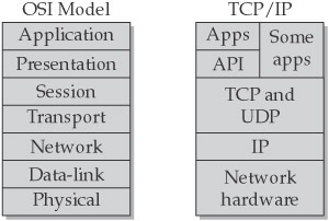
Figure 2-1: The OSI reference model compared with TCP/IP
Internet Protocol (IP)
IP (the Internet Protocol) provides a basic framework for the transport of traffic from source to destination on the Internet. (See RFC 1180 for a TCP/IP tutorial; www.faqs.org/ rfcs/rfc1180.html). By design, it functions as an encapsulation (wrapper) and transport mechanism for this traffic. There is a header checksum to validate that the packet header, but not necessarily the data, has not been corrupted in transit. However, IP provides no facilities for retransmission or error correction.
Best Effort Delivery
IP is responsible for the routing and delivery of packets on the Internet. If a packet is lost in transmission, as, for instance, during a period of congested activity, IP will not, of itself, trigger a retransmission. Instead, it is up to the higher-level protocol to detect that the packet has not been delivered and to take corrective action. IP will also be the transport mechanism for that corrective action, so it is possible that the first corrective action taken may, in turn, not be delivered. The higher-level protocols built on top of IP are expected to implement the necessary error-correction measures for that eventuality. TCP, for instance, has mechanisms to trigger multiple retransmissions. Only after repeated failures to communicate does TCP decide that the transport layer (IP) is fatally broken and, in this case, it provides a notification to the application requesting the communication.
Encapsulation
In the layered approach we have been discussing, each layer is embedded (or encapsulated) in a wrapper from the next lower-level protocol. On an Ethernet network, for instance, the actual wire protocol consists of Ethernet frames, which are addressed using 48-bit hardware addresses for the source and destination Ethernet adapters, and this includes a cyclical redundancy check (CRC) code to ensure reliability. Embedded in the data portion of this frame will be an IP packet, which encodes its source and destination using 32-bit IP addresses, and it also contains a checksum for reliability. Embedded as the data portion of the IP packet is a protocol-specific packet. In the case of TCP or UDP, this will contain source and destination ports, along with yet another checksum. The data portion of this packet will consist of the application or presentation layer data. Thus, each successive layer’s message is treated as data by the layer below it, which provides an extensible framework (see Figure 2-2).
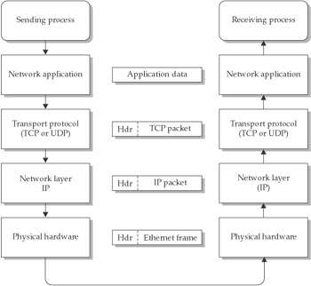
Figure 2-2: Encapsulation and data flow in an IP network
Although having multiple checksums may seem redundant, the design actually allows each layer to detect faults emanating from the layer before it, and to take appropriate action. If the implementation employed only one check code, the traffic would need to travel completely from source to destination before any transmission faults could be detected. Using multiple checksums allows for detection of faults on the local Ethernet using the Ethernet CRC, faults in clean packet transmission between connected networks via the IP checksum, and faults in delivery to the final destination by the protocol-specific checksum. Corrective action can thus be taken at the point where the fault occurred. The redundancy contributes to the reliability and efficiency of the Internet, as well as assisting in failure detection.
The IP Header
The standard IP header is defined in RFC 791 and is shown in Figure 2-3. It consists of a minimum of 20 bytes and ranges up to a maximum of 60 bytes. Embedded in the data portion of the IP packet is the protocol-specific packet (such as a TCP or UDP packet), as discussed earlier.
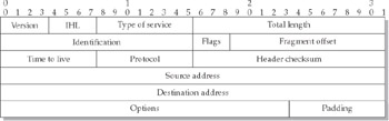
Figure 2-3: Internet datagram header
These are the header fields:
- Version number A 4-bit field (values from 0 to 15) that specifies which version of IP the packet refers to. On the current Internet, this value will generally be 4, although the next generation IPv6 uses a value of 6.
- Internet header length (IHL) A 4-bit field (values from 0 to 15) that specifies the length of the header in 32-bit (4-byte) words. Padding bytes are added to fill up the header to a multiple of 32 bits. Note that the maximum header length is thus 15 x 4 bytes = 60 bytes.
- Type of service (TOS) An 8-bit field (values from 0 to 255) that encodes the service type desired for the packet. This field has been slowly gaining in usage. It encodes, via bit-level fields, the desired delivery characteristics of the packet from the following types: minimize delay, maximize throughput, maximize reliability, minimize monetary cost, and normal service. Routers can use this information to make routing decisions to conform to these requests.
- Total length A 16-bit field (values from 0 to 65,535) that specifies the total length of the packet in bytes. There are few, if any, physical media that can directly transport a packet of the maximum size. If the packet is larger than the physical media can transport, the packet will be fragmented into multiple smaller packets that the media can transport. The next three fields support this fragmentation process.
- IP identification A 16-bit field (values from 0 to 65,535), used to tie the fragments of a packet together. All fragments of an original packet will have this field replicated from the original packet to allow the fragments to be identified and reassembled into the original packet.
- Flags A 3-bit field (values from 0 to 7) that contains three flags (most normal packets will have these 3 bits set to 000):
- Reserved (should always be 0)
- Do Not Fragment bit (D), which can have the following values:
- 0 Packet may be fragmented during transport
- 1 Packet is not to be fragmented (ICMP error message returned to the sending host if the packet reaches a router which needs to fragment the packet, but cannot due to this bit being set)
- More Fragments bit (M), which can have the following values:
- 0 This is the last (or only) fragment
- 1 More fragments exist
- Fragment offset A 13-bit field (values from 0 to 8,191) that when multiplied by 8 gives the offset into the reassembled packet of the current fragment. In an unfragmented packet, this field will be set to 0.
- Time to live (TTL) An 8-bit field (values from 0 to 255) that specifies the lifetime of the packet in the Internet—each time a packet takes another hop through a router, this field is decremented by one. If the TTL value drops to zero, the packet is discarded, and an ICMP TTL exceeded message is sent back to the originating system. This field ensures that packets cannot persist on the Internet indefinitely in the event of a routing loop or other malfunction. Various operating systems have default settings for this field, but rarely is a value of more than 32 necessary in the current Internet.
- Protocol An 8-bit field (values from 0 to 255) that identifies which protocol is being used by the message being transported in this packet. The data portion of the IP packet contains the protocol-dependent header, as well as the actual data being transported between the communicating systems. These are some common values:
- 1 ICMP
- 6 TCP
- 17 UDP
- IP header checksum A 16-bit field (values from 0 to 65,535) that is a checksum of the IP header computed using ones-complement arithmetic. Each hop from one router to the next will cause this field to be recomputed as the header contents change, the most common change being that the TTL field will be decremented, although fragmentation, and some options, such as Record route, and Internet timestamp can also alter the header.
- Source address A 32-bit field that contains the source IP address of the packet. The traditional dotted format (1.2.3.4) is a convenient designation for the four bytes that make up this 32-bit field.
- Destination address A 32-bit field that is the destination IP address of the packet.
- Options A 0- to 40-byte field. Multiple optional features are allowed in this field, some of which have security implications.
- Padding A series of 8-bit bytes consisting of all 0’s to pad the header up to the number of 32-bit words specified in the IHL field.
- Data This field contains the data portion of the IP packet. Its length should be the difference between the Total length field and the IHL field (which, being a count of 32-bit words, must be multiplied by 4 to convert to bytes). Its contents are dependent on the protocol in use, but will typically consist of a protocol header and data bytes.
IP Fragmentation
It was understood by the developers of the IP protocol suite that a sending host might have little or no idea of the characteristics of the physical network through which traffic may be routed, and thus could not adjust packet sizes to fit the requirements of that network. Also, as traffic routing is an adaptive, dynamic process, a packet size appropriate for a known network may not be appropriate for an alternative routing pathway. If the preferred pathway goes down for any reason, routing protocols will attempt to develop alternative pathways, and they may not have the same Maximum Transmission Unit (MTU—the maximum packet size that the media will support).
These considerations drove the development of a packet fragmentation and reassembly process. The decision to fragment a packet is made by a router when the MTU of the next hop is smaller than the packet size. The packet can be flagged to disallow fragmentation, in which case an ICMP error message (“fragmentation needed, but Do Not Fragment bit set”) is sent back to the originating host. Otherwise, the original packet will be split into two or more packets containing the fragments and the regenerated IP header with changes made to the appropriate fields and a recalculated checksum.
Fragmentation could take place several times, as one router may split a packet to match its MTU, then pass the fragments on to another router that may have an even smaller MTU, thus necessitating another fragmentation of the previously fragmented packet. Thus, the receiving host is the most reasonable place to reassemble the packet, although IDSs often perform reassembly as well, in order to examine packet contents.
Three fields in the IP header are used to support the fragmentation of packets:
- IP identification This 16-bit field is the glue that binds the fragments together—every packet is stamped with this field, which on modern systems is generated via a pseudo-random process. For each IP packet thereafter, this number is generally incremented by 1. Each fragment of the original packet will contain the same value in the IP ID field, and the receiving host will use this value to collect together all the fragments for reassembly. Note that since this field is only 16 bits long, the value must wrap around after 65,535 packets.
- Fragmentation offset This 13-bit field defines which portion of the original packet the current fragment references. As the maximum packet size in IP is 65,535 bytes, which is represented in 16 bits, it would seem that 16 bits would be required to identify a fragment offset, yet this field is only 13 bits long. The solution is to multiply the fragmentation offset field by 8 (23). This means that packets are only split on multiples of 8 bytes, which is certainly fine-grained enough.
- Flags This 3-bit field has three 1-bit flags: a reserved bit that should always be 0, a Do Not Fragment bit that indicates whether fragmentation is allowed for this packet, and a More Fragments bit that indicates whether further fragments are being sent or not.
For an unfragmented packet, the fragmentation offset will be set to 0, and the More Fragments bit will be cleared, indicating that the packet is complete.
The receiving system will collect the fragments, identified by the IP ID field, until the last fragment is received, which is signified by a 0 in the More Fragments bit. If there are no holes in the completed packet, the packet is ready for further processing. If a fragment was not received, there will be a hole in the buffer, and the system will have to wait until it is received. If a timeout occurs before IP has received every fragment, the received buffer will be discarded, and depending on the upper-level protocol, the entire packet may be retransmitted, with the possibility of fragmentation occurring again.
RFC 1122 recommends that the reassembly time be between 60 and 120 seconds, and that an ICMP time-exceeded error be sent to the source host if the timer expires and the first fragment of the datagram has been received. This ICMP message contains the first 64 bits of fragment 0 (or less if the fragment is less than 8 bytes long).
Fragmentation solves the problems of varying frame sizes between communicating hosts at a performance penalty, but, as we shall see in Chapter 3, security problems can result from fragments. Fragments have been used to evade firewalls and intrusion-detection systems. Wouldn’t it be nice for systems to be able to determine the maximum size packets that could be transmitted on a link, and thus avoid the overhead of using fragmentation? There is, in fact, a process that determines the MTU between two hosts so that (unless the route changes) packets can be sent without resorting to fragmentation. It’s called Path MTU discovery.
Path MTU Discovery
As was mentioned in the previous section, it would be desirable for systems to determine the maximum MTU they could use in communications to avoid the overhead of fragmentation. According to RFC 791, all devices talking to IP must support a minimum MTU of 68 bytes, so fragmentation can be avoided by transmitting IP packets of 68 bytes which allows for an IP header of up to 60 bytes, and a fragment size of 8 bytes. Unfortunately, most useful packets will not fit into 68 bytes, so they may need to be fragmented anyway.
However, it is possible, by the use of some trickery, for a host to determine the maximum MTU that a link between two systems will support, as follows:
- A host will assemble a maximum-size test packet (as defined by the interface MTU), set the Do Not Fragment bit, and send it on the wire to the destination.
- If the packet reaches a router that would need to fragment the packet to forward it, but cannot, due to the Do Not Fragment bit, the router will send back an ICMP “fragmentation needed, but Do Not Fragment bit set” error message.
- When the sending host receives the ICMP message, it will know that one of the links between the two hosts requires a smaller MTU, and thus can send a smaller test packet in the same manner. The appropriate size can be determined mathematically by dividing the packet size in half, or by successively trying popular default packet sizes for various media (4,352 for FDDI, 1,500 for Ethernet, 576 for X.25 and ISDN, and so on), until a suitable frame size is discovered that can accommodate the full end-to-end link without fragmentation.
- If, on the other hand, no ICMP message is received after a suitable time delay, the sending host assumes that traffic can be sent to the target without danger of fragmentation.
Of course, this mechanism is not completely reliable. ICMP traffic is dependent on the best-effort delivery resources of IP. Although packet corruption is minimized by the use of a checksum, the message could be sent but dropped somewhere in the network, and the sending host would assume that the Path MTU is larger than it really is. Also, since routing is dynamic, the path could change, and the MTU might increase or decrease as a result. Some sites, for example, may have an emergency low-performance link to the Internet, for use when the main link fails. If this emergency link uses a different type of medium than the normal link, it likely will also have a different MTU. If the MTU is lower, traffic using the link will likely be fragmented, exacerbating the performance problems. Thus, it is important that ICMP traffic not be discarded at a network perimeter to allow these sorts of network issues to be signaled to hosts or internal routers for action.
More information on the process of Path MTU discovery can be found in RFC 1191 (www.faqs.org/rfcs/rfc1191.html).
Transmission Control Protocol (TCP)
TCP, the Transmission Control Protocol, can rightly lay claim to being the crown jewel of the IP protocol suite—it is by far the most widely used protocol, as well as the one that is responsible for carrying the majority of the Internet’s useful content. TCP adds to the best-effort delivery capabilities of IP.
TCP Reliable Delivery
TCP, being embedded within an IP packet, paradoxically must employ the unreliable delivery mechanisms of IP to ensure reliability. Of course, perfect reliability is not possible in the real world, due to hardware, routing, and software failures, but TCP nevertheless achieves a high degree of reliability by employing three distinct, cooperating processes:
- TCP checksum The TCP checksum is computed over the entire TCP packet, including the data portion. If the computed checksum does not match the packet contents, the receiving host discards the packet. In that case, the packet timeout mechanism (described below) eventually causes the sending host to retransmit the packet.
- Mutual acknowledgment of received data Each system maintains a count of bytes received properly from the other host (known as the acknowledgment or ACK number), as well as the number of bytes sent to the other host (known as the sequence or SYN number). Both systems thus know the expected amount of traffic that the other host should have seen. If a host fails to acknowledge data sent to it (by failing to increment the ACK number properly), the other host will resend that traffic again upon receipt of the next ACK number that is greater than the expected value (that is, if there is a gap in the sequence of numbers). Thus, each host acknowledges the traffic that the other host has sent, and each host is aware of the traffic that the other side has received.
- Packet timeout As IP’s non-guaranteed delivery may silently drop a packet, TCP will wait for an expected response to the sent packet for a given period of time, and then will retransmit the packet, on the assumption that either the packet or its response was lost. If a host receives a packet that it has already received and responded to, it will assume that the response was lost in transit and will retransmit its initial response.
Retransmissions may occur multiple times with varying timeouts before TCP decides that the IP layer is hopelessly broken—at that point, it will signal an error to the application.
TCP Communications Model
Each TCP connection is uniquely identified by four distinct items (a four-tuple): the IP addresses of the two communicating systems and the TCP ports used by each system. This does not mean that two systems cannot communicate using the same service on more than one connection—multiuser systems support multiple telnet connections from the same client. In such a case, the IP addresses will be the same, and the telnet service will be found on the standard TCP port 23. However, the client system will use a different port for each connection, thus keeping the traffic for each connection distinct.
Under normal conditions, a listening process must be running on the receiving host to accept and respond to TCP connection requests. If a TCP packet is received that is destined for a port with no listeners, a TCP RST packet will be sent back to the source by the receiving host.
TCP uses 16-bit port numbers, which means that there are 65,536 possible ports. These ports are normally divided into two distinct ranges: 0 through 1,023 represent the well-known services that are (on Unix systems) only accessible by the root account. Ports 1,024 through 65,535 are termed ephemeral ports, which user programs can access and use to provide services or use as client ports for establishing connections.
To reliably maintain a connection between two systems requires a well-defined process for session establishment, maintenance, and teardown. This process is described in the following summary of steps, and it is illustrated in Figure 2-4:
- The receiving host socket is in a passive, listening state, awaiting an incoming connection request from the initiator.
- The initiating system sends an initial TCP packet with the SYN flag set, and an initial sequence number (ISN) chosen pseudo-randomly. Each byte transmitted, as well as a few flags (SYN or FIN), will increment this sequence number. In effect, the initiator is signaling that it will start numbering the bytes transferred over the connection starting from the ISN. The SYN flag itself consumes the first sequence number.
- The receiver will respond with a SYN/ACK packet, indicating its readiness to establish a connection, and acknowledging the initiator’s SYN. In the response, the receiver puts the initiator’s ISN+1 in the Acknowledgment field and sets up its own ISN in the SYN field.
- The three-way handshake is then completed when the initiating system sends an ACK packet back to the responding system. The purpose of this packet is to let the responding system know that the connection is fully established.
- At this point, the session is established. When either party wishes to send data to the other, it will send a packet with the ACK flag set, with an acknowledgment of the last sequence number (in the Acknowledgment field) received from the remote host, and with its own sequence number incremented to reflect the amount of data being transmitted. The actual data to be sent is included in the TCP data portion of the packet. If there is no data to be sent, and the host is merely acknowledging the data received from the other party, a packet with no TCP data portion is sent.
- When a system is finished with the communication, it will send a FIN/ACK packet, signaling that it wishes to close the connection. However, a connection cannot be closed by only one side. Rather, by closing the connection, the system is indicating that it has no more data to send. The host receiving the initial FIN sends an ACK acknowledging the FIN, and if that system doesn’t have any more data to send either, it sends a FIN as well. When the system that first closed the connection responds with an ACK of its own, the connection will be considered closed. Either party can also abort the connection by sending a RST/ACK packet, which will cause the connection to be immediately closed.
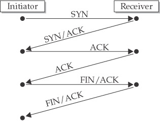
Figure 2-4: Creating and tearing down a TCP connection
The TCP Header
The standard TCP header is defined in RFC 791 and illustrated in Figure 2-5. It consists of a minimum of 20 bytes and a maximum of 60 bytes. The application-specific information, which is delivered to the application program, is located in the data portion of the TCP packet.
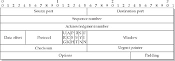
Figure 2-5: TCP header
The TCP header consists of the following fields:
- Source port A 16-bit field (values from 0 to 65,535) that identifies the source port of the connection.
- Destination port A 16-bit field (values from 0 to 65,535) that identifies the destination port of the connection.
- Sequence number A 32-bit field (values from 0 to 232–1) that identifies the current byte count (as of the end of this packet) relative to the initial sequence number (ISN), which is set in the initial SYN packet. Each byte transmitted, as well as the SYN and FIN flags, increment this value.
- Acknowledgment number A 32-bit field (values from 0 to 232–1) that holds the last sequence number of this communication transmitted by the other party and received correctly by the host. In the first packet sent (the initial SYN), this field is undefined.
- Data offset A 4-bit field (values from 0 to 15) that indicates the number of 32-bit words in the header portion of the packet. The maximum size of a TCP header is thus 15 x 4 = 60 bytes. The minimum size of a TCP header (a header without optional arguments) is 5 words, or 20 bytes. Values of 0 through 4 are invalid.
- Reserved A 6-bit field reserved for future expansion—it should always be 0.
- Flags A 6-bit field that contains the following six 1-bit flags:
- URG Urgent
- ACK Acknowledgment
- PSH Push
- RST Reset connection
- SYN Synchronize connection
- FIN Finish
- Window A 16-bit field (values from 0 to 65,535) that indicates the amount of receive buffer space available. This field has important performance implications, as it tells the remote system how much traffic the local host can accept, and thus how many packets the remote host can send before expecting an acknowledgment. The TCP Window Scale option modifies the behavior of this field.
- Checksum A 16-bit field (values from 0 to 65,535). This value is computed using ones-complement arithmetic over a pseudo-header, the TCP header, and the TCP data. The receiving system recomputes this value and drops the packet if the checksum is invalid—in this case, the TCP timeout mechanism will cause the packet to be retransmitted by the sender.
Note The pseudo-header used to compute UDP and TCP checksums includes the source and destination IP addresses, as well as the protocol specific header. At the packet’s final destination, the checksum is recomputed using the source and destination addresses obtained from the header of the IP packet which transported the protocol-specific packet. If the checksums agree, then we can have a high degree of confidence that the packet reached the intended destination host, as well as the correct protocol- specific port.
- Urgent pointer A 16-bit field (values from 0 to 65,535) that points to the last byte of any “urgent” data that an application wishes to transfer immediately to the receiving host, bypassing normal buffering. This field should have a value of 0 unless the Urgent flag is set.
- Options This field can be used for various option capabilities that tune the behavior of the TCP communications. These are padded as necessary to bring the TCP header length to an even multiple of 32 bits.
- Data The application data is placed here. The length of this field should match the total packet size identified in the IP header, minus the Internet header length, minus the TCP data offset (all scaled as appropriate to reflect bytes).
User Datagram Protocol (UDP)
UDP, the User Datagram Protocol, is often used by applications that prefer to avoid the overhead of establishing a TCP connection (such as DNS, NFS, TFTP), or those that can tolerate occasional errors in the interest of efficiency (such as streaming audio or video). UDP is given the Internet protocol number of 17 and is defined in RFC 768 (www.faqs.org/ rfcs/rfc768.html).
The UDP model is much simpler than that of TCP. There is no session-level error checking or retransmission built into the protocol. The packets do, however, contain a checksum. A receiving host can verify this checksum to ensure that the packet has not been corrupted during transit. The sending host, however, does not receive a protocol-level acknowledgment that the packet was delivered. If any such reliability is needed, it is left to be implemented at the application level.
An example of an application-level, reliable protocol built on UDP is the Trivial File Transfer Protocol, or TFTP (see RFC 1350, www.faqs.org/rfcs/rfc1350.html), which consists of server and client implementations. These two processes exchange crafted UDP packets that contain handshaking information along with the data being transferred. The application programs must handle this handshaking themselves, as well as extracting the data. Contrast this with TCP data transfers, where the application receives only the data bytes and needn’t concern itself with the details of the data transfer.
UDP uses 16-bit port numbers, as does TCP, but UDP and TCP ports are distinctly different. As with TCP, there generally needs to be a listening process at the receiving host to accept and respond to the request. Under normal circumstances, the arrival of a UDP packet destined for a port with no listeners will cause the receiving host to respond with an ICMP “port unreachable” message.
UDP Header
The UDP header (shown in Figure 2-6) consists of four 16-bit fields, totaling 8 bytes in length. These fields follow immediately after the IP header:
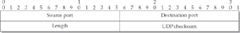
Figure 2-6: UDP header
- Source port A 16-bit field (values from 0 to 65,535).
- Destination port A 16-bit field (values from 0 to 65,535).
- Length A 16-bit field (values from 0 to 65,535). This field is the length of the UDP header and data bytes, and it does not include the IP header. Typically, the UDP packet length should be the difference between the IP total length field and the IP header length. If there is a discrepancy, most implementations will discard the packet as invalid.
- UDP checksum A 16-bit field (values from 0 to 65,535). This value is computed using ones-complement math over a pseudo-header, the UDP header, and the UDP data. The checksum is actually optional in UDP, and if this field is set to 0, the checksum will not be examined by the receiving host. This field was originally put in place as a performance-enhancing measure, but currently all packets should have a checksum. Those that do not may bear further examination for possible intrusion attempts.
Internet Control Message Protocol (ICMP)
ICMP, the Internet Control Message Protocol, is the signaling mechanism used in IP networks to communicate error conditions and other control information about network conditions. As IP is a best-effort delivery protocol, failure to deliver a packet to its destination is not considered a network-level error. Protocols or applications need additional mechanisms to ensure reliability. For instance, as was mentioned earlier, TCP employs an acknowledgment protocol, along with retransmission of lost packets after a suitable time.
ICMP is given the protocol identifier of 1 in the standard IP packet, and it is documented in RFC 792 (www.faqs.org/rfcs/rfc792.html). All conforming implementations of IP must include ICMP, as it is integral to signaling error conditions on the network.
ICMP messages are of interest both to end-hosts and intermediate routers, although some messages are generally only sent by routers. It is never permissible for an ICMP error message to be generated as the result of receiving an ICMP error message—this avoids the infinite recursion of ICMP message generation (see RFC 1122, www.faqs.org/rfcs/ rfc1122.html). It is also forbidden to send an ICMP message as the result of a datagram that references multiple hosts, such as a broadcast or multicast message, or upon receipt of a noninitial fragment (see the “IP Fragmentation” section earlier in the chapter). These restrictions are designed to prevent broadcast storms.
Broadly, there are two classes of ICMP messages: ICMP error messages and ICMP query/response messages. Each ICMP error message will be constructed from the Internet header, and (at least) the first eight bytes of the IP packet payload (which generally is data from the header of the lower-level protocol, such as TCP or UDP).
ICMP Packet Format
The ICMP packet format is illustrated in Figure 2-7. Note that it includes a checksum for reliability.
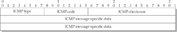
Figure 2-7: ICMP packet format
These are the fields in the ICMP packet:
- ICMP type An 8-bit field (values from 0 to 255) that encodes the type of ICMP message being sent. These are some common values:
- 3 Destination unreachable
- 5 Redirect
- 4 Source quench
- 11 Time exceeded
- ICMP code An 8-bit field that encodes a subcategory of the type.
- ICMP checksum A 16-bit field.
- ICMP message-specific data A variable length field. All ICMP error messages will store the Internet header and at least the first eight bytes of the Internet data (which typically will be the protocol header). This information allows the receiving system to identify the hosts and port numbers that the error message refers to.
Address Resolution Protocol (ARP)
IP addresses of 32 bits (or the upcoming 128-bit IPv6 standard) are logical addresses only. This means that the network adapter itself has no preconceived notion of what its IP address is, but rather is assigned an address by a hardware mechanism. This is an important distinction, since it would be difficult to replace a failed network adapter, or to change the IP address of an existing adapter, unless the hardware address were decoupled from the logical address.
Ethernet hardware addresses (called MAC addresses), by way of example, are 48 bits in length and are theoretically unique throughout the world. Vendors are assigned generous blocks of addresses out of this space so that each individual network adapter will have a unique address. To send a packet to another Ethernet card requires that the sender know the MAC address of the target system. At the IP level, though, the only information that the sender has is the IP address, which is not, as was mentioned, tied to a specific Ethernet card. Thus, a mechanism is needed to provide a mapping from the IP address to the hardware address of the card. ARP provides such a mechanism.
| Note |
Although MAC addresses are supposed to be unique, in practice, some off-brand vendors have been known to use address space not allocated to them, or to randomly address cards. In the unlikely event that two network cards on the same subnet are utilizing the same MAC address, neither system will likely be able to successfully communicate with others. |
When a system wishes to send a packet to a system whose hardware address is unknown, it will send out a network broadcast message that, in effect, asks, “Who, on this network, has this IP address?” The system that is using that IP address will respond with a message saying, “I have this address, and here’s my hardware address.” In order to increase the efficiency of the network, each system keeps a table of recently used hardware and IP addresses in memory, called the ARP cache. Typically, these recent addresses will expire after 20 minutes, in which case another ARP request will be made upon the next access to the system.
Diskless workstations suffer from an opposite problem—they know their hardware address but do not know their IP address. Reverse Address Resolution Protocol (RARP) is used to broadcast the request, and a RARP server will send a message back indicating the host’s IP address. However, RARP has been mostly superceded by more advanced protocols, such as the Bootstrap Protocol (BOOTP) and Dynamic Host Configuration Protocol (DHCP).
ARP Packet Format
ARP was designed with the flexibility to handle different media with varying hardware address lengths, so length fields are included to allow differing field sizes. Figure 2-8 illustrates the ARP packet format.
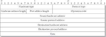
Figure 2-8: ARP packet format
The ARP packet contains the following fields:
- Hardware type A 16-bit field (values from 0 to 65,535) that encodes the type of hardware involved. The code for Ethernet is 1.
- Protocol type A 16-bit field (values from 0 to 65,535) that encodes the type of addressing scheme being used. The value for IP addressing is 0x0800 (in hexadecimal).
- Hardware address length An 8-bit field (values from 0 to 255) that specifies the size in bytes of the hardware address. For Ethernet, this value will be 6.
- Protocol address length An 8-bit field (values from 0 to 255) that specifies the size in bytes of the protocol addressing being used. For IPv4, this value will be 4.
- Operation code A 16-bit field (values from 0 to 65,535) indicating the type of operation to be performed. These are some common values:
- 1 ARP request
- 2 ARP reply
- 3 RARP request
- 4 RARP reply
- Source hardware address A variable length field (the length depends on the value in the hardware address length field).
- Source protocol address A variable length field (the length depends on the value in the protocol address length field).
- Destination hardware address A variable length field (the length depends on the value in the hardware address length field).
- Destination protocol address A variable length field (the length depends on the value in the protocol address length field).
- Data Any additional data that the protocol requires.
When an ARP or RARP packet is sent requesting information, the unknown fields are set to 0 by the sender and are filled in by the responding host.
Routing
Except when two communicating systems are part of the same subnet, they will not have any direct way to communicate with each other. Rather, they must forward their traffic through a router, which will forward the traffic on their behalf. The router, in turn, if not on the same subnet as the ultimate destination, will forward the traffic to another router, until the ultimate destination is reached. Each hop a packet takes results in the packet being subtly changed before it is forwarded:
- The TTL (time to live) field in the IP header is decremented by one. If this results in the value becoming 0, the router will send an ICMP error packet (“TTL exceeded”) back to the sender of the packet, and the packet itself is dropped. There may also be some other header changes as a result of some IP options (record route, timestamp, or others).
- If the packet is fragmented in order to traverse the next hop, multiple packets will be generated by the router.
- The IP checksum is recomputed to account for the header changes. The ones-complement arithmetic that is used allows for this to be done in a single step, rather than by rechecksumming the entire header.
Eventually, through this forwarding process, a packet will reach a router that has knowledge of the ultimate destination, and that will forward the packet to its destination. Of course, it is also possible that the destination system doesn’t exist, in which case the packet will be dropped and an ICMP “destination unreachable” error packet will be sent back to the originator.
A Practical Example of Routing
Let’s examine, in a little more detail, what happens to a packet as it traverses from host A to host B through a few routers. Suppose an application program on host A wants to initiate a TCP communication to an application on host B. We will assume that host A already knows the IP address of host B. (If this is not the case, the sequence of events described in the section on DNS applies.) The following are the steps that will be taken:
- Host A constructs a TCP header using the operating system defaults (such as TTL) with the SYN flag set, checksums calculated, and includes the rest of the packet.
- Prior to the packet actually being sent down the wire, the operating system on host A consults its routing table to determine what host is the next destination for the packet. Unless the two hosts are directly connected, this will be an intermediate router that can forward the packet to its next destination. Most systems have a default route to their local router, but many more complicated routing tables can be constructed.
- The IP software on host A consults its ARP cache, which contains mappings between the high-level IP addresses and the low-level hardware addresses. If the hardware address of the next hop is unknown, an ARP request is made to determine this information.
- The packet is encapsulated in the low-level framing appropriate for the physical medium (including low-level hardware addressing for the next hop), and it is sent on the wire.
- Router 1 sees a packet addressed to its hardware address, picks it up, and checks the header for consistency. Packets with incorrect checksums are silently dropped, and the responsibility lies with the originating system (host A) to resend the packet if no response has been received after a suitable timeout.
- Router 1 decrements the TTL, and if the TTL has reached 0, an ICMP error message is sent back to the originating host (host A) signaling this fact. Because of the TTL change and other obscure options that can affect the packet contents, the checksum is recomputed.
- Router 1 must make a decision about what to do with the packet by consulting its rule set—it may decide to drop the packet (with or without notification to the originating host), modify it, or forward it. If the packet is addressed to router 1 itself, it will be sent to the operating system of the router for processing.
- If the packet is to be forwarded, router 1 will also decide whether the packet needs to be fragmented by comparing the size of the packet with the MTU that the next hop requires.
- Router 1 consults its ARP cache, and issues an ARP request if the address of the next hop is unknown. In general, this will only need to be done for the first packet that is transmitted along a particular route, and periodically afterwards to ensure that the cache doesn’t become stale.
- Since the packet is to be sent on to host B, router 1 encapsulates the packet in the low-level framing appropriate for the physical medium (including the low-level hardware addressing for the next hop), and it is sent on the wire to router 2.
- Router 2 will follow a sequence of events similar to those router 1 followed, and (if all goes well) will end up forwarding the packet to host B.
- Host B receives the packet and examines the IP checksum and TTL. If those are okay, and if host-level firewalling is enabled, the packet will typically be examined by the firewall software and either be accepted or rejected, although some processing may occur later.
- Assuming the packet has been allowed access to the TCP layer of host B, the TCP layer will ensure that the TCP checksum is valid.
- Host B will then examine its table of connections, referenced by the four-tuple of source host, source port, destination host, and destination port, to see if this packet refers to an established connection.
- In this example, host B sees that there is no established connection and will then check whether there is a listening socket on the destination port. If there is no such socket, a TCP RST packet will be constructed and sent back to the originating host, as an indication that the port on the destination is closed. Or, if the packet does not contain a SYN, a TCP RST will be initiated by host B, because a SYN packet must be the first packet of a connection.
- If the packet passes these tests, a connection record will be established, options will be extracted (such as initial sequence number, desired window size, and so on), host B’s options will be included, and a SYN/ACK packet will be created for transmission back to host A.
- Host B will then send the SYN/ACK packet to host A using the same steps of events that host A used to send the original packet.
From this simple (!) example of transferring one packet between two hosts, it can be seen that Internet communication is a complex process that requires all cooperating hosts to adhere to defined standards. As Chapter 3 will show, though, there is enough wiggle- room in some of these areas for malicious activities to take place.
Domain Name System (DNS)
DNS, the Domain Name System, is a worldwide distributed database whose most important function is to translate from the human-readable system names that we are all familiar with (such as www.osborne.com), into the simpler (but more rigid) 32-bit IP addresses. One benefit this database provides is that it is easy for web sites to migrate to different hosting companies, because only the DNS records need to be changed to reflect the changed IP address—all references to the host name will follow. As we shall see in later chapters, however, if the DNS records are modified or forged, an attacker can redirect traffic to an entirely different host than the expected legitimate host.
DNS was designed in 1984 to solve an escalating problem with the host-name-to-IP- address mapping system. Previously, all hosts needed to maintain a table (a file called hosts) with periodic updates. As the Internet grew, this host table became unwieldy and unmaintainable. DNS solves this problem by delegating the name service information to the owners of the domain, who maintain a table only of their own systems or subdomains.
DNS uses the concept of domain name space, which can be represented as an inverted tree, as shown in Figure 2-9. Each node on the tree represents a domain, and everything below a node is part of that domain, until the final leaf node is reached, which represents an individually named system. For example, in Figure 2-9 the system gene is part of the bar domain, which in turn is part of the .com domain, which along with the other “top-level” domains, are all subdomains of the Internet root domain.
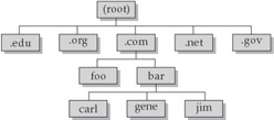
Figure 2-9: Domain name space
To resolve a name to its IP address, a host will examine its host table (which still exists in most systems in a legacy form), and if the name is not found, the host will forward the request to its name server. (The order of this search is configurable on some systems). The name server, if it has recent knowledge of the name in question (all DNS records time out to ensure that the data isn’t stale) will immediately respond with the IP address. If the name server is unfamiliar with the domain name, it will ask a server higher up the tree, which in turn will continue going up the tree until an answer is received. Under some circumstances, name resolution can take many seconds, thus appearing to the user as if the system has frozen. The recursive nature of the queries is one reason for these potential delays. Also, since DNS typically communicates over UDP (on port 53), it is possible that the packets could be lost, so multiple attempts are often made to resolve a name.
Summary
We’ve explored the protocols and processes that drive the modern Internet: IP, the transport mechanism to deliver the traffic; TCP for the establishment of virtual circuits for two-way communication; UDP for lighter weight transport of data, without the overhead of creating a connection; and ICMP for transporting error or status conditions between hosts. We’ve also seen some of the infrastructure mechanisms, and examined how all of these mechanisms tie together to provide reliable delivery of data throughout the Internet. We’ve also discussed the complexity of the network infrastructure. It is a monument to the designers of the Internet that it functions so well. Complex systems, however, are often subject to damage or abuse by malicious parties.
In Chapters 3, 4, and 5, we will build on the foundations presented here, and delve into low-level network abuses, as well as specific application protocol abuses. We will also examine common programming errors that allow for attacks targeting network-aware programs. Get ready! The fun’s just beginning…
Part I - Intrusion Detection: Primer
- Understanding Intrusion Detection
- Crash Course in the Internet Protocol Suite
- Unauthorized Activity I
- Unauthorized Activity II
- Tcpdump
Part II - Architecture
Part III - Implementation and Deployment
Part IV - Security and IDS Management
EAN: 2147483647
Pages: 163
