Bit Manipulation
A computer contains many integrated circuits that enable it to perform its functions. Each chip incorporates from a few to many thousand logic gates, each an elementary circuit that performs Boolean and, or, exclusive or, or not operations on bits that are represented by electronic states. The CPU is usually the most complex integrated circuit in a PC.
Previous chapters have examined the 80x86 microprocessors' instructions for moving data, performing arithmetic operations, handling strings, branching, and utilizing subroutines. The 80x86 (and most other CPUs) can also execute instructions that perform Boolean operations on multiple pairs of bits at one time. This chapter defines the Boolean operations and describes the 80x86 instructions that implement them. It also covers the instructions that cause bit patterns to shift or rotate in a byte, word, or doubleword, or to shift from one location to another. Although bit manipulation instructions are very primitive, they are widely used in assembly language programming, often because they provide the sort of control that is rarely available in a high-level language. The chapter contains several application examples, including the procedure that is called by the atoi macro; this procedure uses bit manipulation instructions in several places.
Logical Operations
Many high-level languages allow variables of Boolean type; that is, variables that are capable of storing true or false values. Virtually all high-level languages allow expressions with Boolean values to be used in conditional (if) statements. In assembly language the Boolean value true is identified with the bit value 1 and the Boolean value false is identified with the bit value 0. Figure 8.1 gives the definitions of the Boolean operations using bit values as the operands. The or operation is sometimes called "inclusive or" to distinguish it from "exclusive or" (xor). The only difference between or and xor is for two 1 bits; 1 or 1 is 1, but 1 xor 1 is 0; that is, "exclusive" or corresponds to one operand or the other true, but not both.
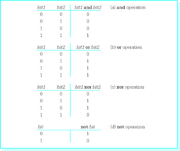
Figure 8.1: Definitions of logical operations
The 80x86 has and, or, xor, and not instructions that implement the logical operations. The formats of these instructions are
 and destination, source
 or destination, source
 xor destination, source
 not destination
The first three instructions act on pairs of doublewords, words, or bytes, performing the logical operations on the bits in corresponding positions from the two operands. For example, when the instruction and bx,cx is executed, bit 0 from the BX register is "anded" with bit 0 from the CX register, bit 1 from BX is "anded" with bit 1 from CX, and so forth to bit 15 from BX and bit 15 from CX. The results of these 16 and operations are put in the corresponding positions in the destination.
The not instruction has only a single operand. It changes each 0 bit in that operand to 1 and each 1 bit to 0. For example, if the AH register contains 10110110 and the instruction not ah is executed, then the result in AH will be 01001001. This is sometimes called "taking the one's complement" of the operand.
The not instruction does not affect any flag. However, each of the other three Boolean instructions affects CF, OF, PF, SF, ZF, and AF. The carry flag CF and overflow flag OF flags are both reset to 0; the value of the auxiliary carry flag AF may be changed but is undefined. The parity flag PF, the sign flag SF, and the zero flag ZF are set or reset according to the value of the result of the operation. For instance, if the result is a pattern of all 0 bits, then ZF will be set to 1; if any bit of the result is not 0, then ZF will be reset to 0.
The and, or, and xor instructions all accept the same types of operands, use the same number of clock cycles for execution, and require the same number of bytes of object code. They are summarized together in Fig. 8.2. Information about the not instruction is given in Fig. 8.3.
|
Destination |
Source |
Clock Cycles |
Number of Bytes |
Opcode |
||||
|---|---|---|---|---|---|---|---|---|
|
Operand |
Operand |
386 |
486 |
Pentium |
and |
or |
xor |
|
|
register 8 |
immediate 8 |
2 |
1 |
1 |
3 |
80 |
80 |
80 |
|
register 16 |
immediate 8 |
2 |
1 |
1 |
3 |
83 |
83 |
83 |
|
register 32 |
immediate 8 |
2 |
1 |
1 |
3 |
83 |
83 |
83 |
|
register 16 |
immediate 16 |
2 |
1 |
1 |
4 |
81 |
81 |
81 |
|
register 32 |
immediate 32 |
2 |
1 |
1 |
6 |
81 |
81 |
81 |
|
AL |
immediate 8 |
2 |
1 |
1 |
2 |
24 |
0C |
34 |
|
AX |
immediate 16 |
2 |
1 |
1 |
3 |
25 |
0D |
35 |
|
EAX |
immediate 32 |
2 |
1 |
1 |
5 |
25 |
0D |
35 |
|
memory byte |
immediate 8 |
7 |
3 |
3 |
3+ |
80 |
80 |
80 |
|
memory word |
immediate 8 |
7 |
3 |
3 |
3+ |
83 |
83 |
83 |
|
memory doubleword |
immediate 8 |
7 |
3 |
3 |
3+ |
83 |
83 |
83 |
|
memory word |
immediate 16 |
7 |
3 |
3 |
4+ |
81 |
81 |
81 |
|
memory doubleword |
immediate 32 |
7 |
3 |
3 |
6+ |
81 |
81 |
81 |
|
register 8 |
register 8 |
2 |
1 |
1 |
2 |
22 |
0A |
32 |
|
register 16 |
register 16 |
2 |
1 |
1 |
2 |
23 |
0B |
33 |
|
register 32 |
register 32 |
2 |
1 |
1 |
2 |
23 |
0B |
33 |
|
register 8 |
memory byte |
6 |
2 |
2 |
2+ |
22 |
0A |
32 |
|
register 16 |
memory word |
6 |
2 |
2 |
2+ |
23 |
0B |
33 |
|
register 32 |
memory doubleword |
6 |
2 |
2 |
2+ |
23 |
0B |
33 |
|
memory byte |
register 8 |
7 |
3 |
3 |
2+ |
20 |
08 |
30 |
|
memory word |
register 16 |
7 |
3 |
3 |
2+ |
21 |
09 |
31 |
|
memory doubleword |
register 32 |
7 |
3 |
3 |
2+ |
21 |
09 |
31 |
Figure 8.2: and, or, and xor instructions
|
Clock Cycles |
Number of Bytes |
||||
|---|---|---|---|---|---|
|
Destination Operand |
386 |
486 |
Pentium |
Opcode |
|
|
register 8 |
2 |
1 |
1 |
2 |
F6 |
|
register 16 |
2 |
1 |
1 |
2 |
F7 |
|
register 32 |
2 |
1 |
1 |
2 |
F7 |
|
memory byte |
6 |
3 |
3 |
2 + |
F6 |
|
memory word |
6 |
3 |
3 |
2 + |
F7 |
|
memory doubleword |
6 |
3 |
3 |
2 + |
F7 |
Figure 8.3: not instruction
It is interesting to note that Fig. 8.2 is almost identical to Fig. 4.5, which showed add and sub instructions. Also, Fig. 8.3 is almost identical to Fig. 4.7, which showed neg instructions. In both cases, the available operand formats are identical, the timings are identical, and even many of the opcodes are the same. (Recall that when the opcodes are the same, the second byte of the instruction distinguishes between add, sub, and, or, and xor instructions.)
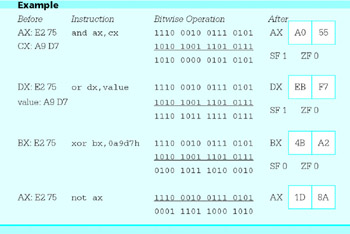
Here are some examples showing how the logical instructions work. To compute the results by hand, it is necessary to expand each hex value to binary, do the logical operations on corresponding pairs of bits, and convert the result back to hex. These expansions are shown in the examples. Most hex calculators perform the logical operations directly.
Each of the logical instructions has a variety of uses. One application of the and instruction is to clear selected bits in a destination. Note that if any bit value is "anded" with 1, the result is the original bit. On the other hand, if any bit value is "anded" with 0, the result is 0. Because of this, selected bits in a byte or word can be cleared by "anding" the destination with a bit pattern that has 1s in positions that are not to be changed and 0s in positions that are to be cleared.
For example, to clear all but the last four bits in the EAX register, the following instruction can be used.
and eax, 0000000fh ; clear first 28 bits of EAX
If EAX originally contained 4C881D7B, this and operation would yield 0000000B:
 0100 1100 1000 1000 0001 1101 0111 1011 4C881D7B
 0000 0000 0000 0000 0000 0000 0000 1111 0000000F
 0000 0000 0000 0000 0000 0000 0000 1011 0000000B
Only one of the leading zeros is needed in 0000000fh, but coding seven zeros helps clarify the purpose of this operand. The trailing hex digit f corresponds to 1111 in binary, providing the four 1s that will leave the last four bits in EAX unchanged.
A value that is used with a logical instruction to alter bit values is often called a mask. The Microsoft assembler MASM accepts numeric values in decimal, hexadecimal, binary, and octal formats. Hex and binary are preferred for constants used as masks since the bit pattern is obvious for binary values or easy to figure out for hex values.
As illustrated above, the and instruction is useful when selected bits of a byte or word need to be cleared. The or instruction is useful when selected bits of a byte or word need to be set to 1 without changing other bits. Observe that if the value 1 is combined with either a 0 or 1 using the or operation, then the result is 1. However, if the value 0 is used as one operand, then the result of an or operation is the other operand.
The exclusive or instruction will complement selected bits of a byte or word without changing other bits. This works since 0 xor 1 is 1 and 1 xor 1 is 0; that is, combining any operand with 1 using an xor operation results in the opposite of the operand value.
A second use of logical instructions is to implement high-level language Boolean operations. One byte in memory could be used to store eight Boolean values. If such a byte is at flags, then the statement
and flags, 11011101b ; flag5 := false; flag1 := false
assigns value false to bits 1 and 5, leaving the other values unchanged. (Recall that bits are numbered from right to left, starting with zero for the rightmost bit.)
If the byte in memory at flags is being used to store eight Boolean values, then an or instruction can assign true values to any selected bits. For instance, the instruction
or flags, 00001100b ; flag3 := true; flag2 := true
assigns true values to bits 2 and 3 without changing the other bits.
If the byte in memory at flags is being used to store eight Boolean values, then an xor instruction can negate selected values. For instance, the design statement
flag6 := NOT flag6; |
can be implemented as
xor flags, 01000000b ; flag6 := not flag6
A third application of logical instructions is to perform certain arithmetic operations. Suppose that the value in the EAX register is interpreted as an unsigned integer. The expression (value mod 32) could be computed using the following sequence of instructions.
 mov edx,0 ; extend value to quadword
 mov ebx,32 ; divisor
 div ebx ; divide value by 32
Following these instructions, the remainder (value mod 32) will be in the EDX register. The following alternative sequence leaves the same result in the EDX register without, however, putting the quotient in EAX.
 mov edx,eax ; copy value to DX
 and edx,0000001fh ; compute value mod 32
This choice is much more efficient than the first one (see Exercise 2). It works because the value in EDX is a binary number; as a sum it is
bit31*231 + bit30*230 + ... + bit2*22 + bit1*2 + bit0 |
Since each of these terms from bit31*231 down to bit5*25 is divisible by 32 (25), the remainder upon division by 32 is the bit pattern represented by the trailing five bits, those left after masking by 0000001F. Similar instructions will work whenever the second operand of mod is a power of 2.
A fourth use of logical instructions is to manipulate ASCII codes. Recall that the ASCII codes for digits are 3016 for 0, 3116 for 1, and so forth, to 3916 for 9. Suppose that the AL register contains the ASCII code for a digit, and that the corresponding integer value is needed in EAX. If the value in the high-order 24 bits in EAX are known to be zero, then the instruction
sub eax, 00000030h ; convert ASCII code to integer
will do the job. If the high-order bits in EAX are unknown, then the instruction
and eax, 0000000fh ; convert ASCII code to integer
is a much safer choice. It ensures that all but the last four bits of EAX are cleared. For example, if the EAX register contains 5C3DF036, junk in the high order bits, and the ASCII code for the character 6 in AL, then and eax,0000000fh produces the integer 00000006 in EAX.
The or instruction can be used to convert an integer value between 0 and 9 in a register to the corresponding ASCII character code. For example, if the integer is in BL, then the following instruction changes the contents of BL to the ASCII code.
or bl,30h ; convert digit to ASCII code
If BL contains 04, then the or instruction will yield 34:
 0000 0100 04
 0011 0000 30
 0011 0100 34
With the 80x86 processors, the instruction add bl,30h does the same job using the same number of clock cycles and object code bytes. However, the or operation is more efficient than addition with some CPUs.
An xor instruction can be used to change the case of the ASCII code for a letter. Suppose that the CL register contains the ASCII code for some upper- or lowercase letter. The ASCII code for an uppercase letter and the ASCII code for the corresponding lowercase letter differ only in the value of bit 5. For example, the code for the uppercase letter S is 5316 (010100112) and the code for lowercase s is 7316 (011100112). The instruction
xor cl, 00100000b ; change case of letter in CL
"flips" the value of bit 5 in the CL register, changing the value to the ASCII code for the other case letter.
The 80x86 instruction set includes test instructions that function the same as and instructions except that destination operands are not changed. This means that the only job of a test instruction is to set flags. (Remember that a cmp instruction is essentially a sub instruction that sets flags but does not change the destination operand.) One application of a test instruction is to examine a particular bit of a byte or word. The following instruction tests bit 13 of the DX register.
test dx, 2000h ; check bit 13
Note that 2000 in hex is the same as 0010 0000 0000 0000 in binary, with bit 13 equal to 1. Often this test instruction would be followed by a jz or jnz instruction, and the effect would be to jump to the destination if bit 13 were 0 or 1, respectively.
The test instruction can also be used to get information about a value in a register. For example,
test cx, cx ; set flags for value in CX
"ands" the value in the CX register with itself, resulting in the original value. ("Anding" any bit with itself gives the common value.) The flags are set according to the value in CX. The instruction
and cx, cx ; set flags for value in CX
will accomplish the same goal and is equally efficient. However, using test makes it clear that the only purpose of the instruction is testing.
The various forms of the test instruction are listed in Fig. 8.4. They are almost the same as for and, or, and xor instructions. Only the accumulator can be the destination when the source is in memory, but MASM lets you specify any register as the destination and transposes the operands to have the memory operand first, one of the allowable formats.
|
Destination |
Source |
Clock Cycles |
Number of Bytes |
|||
|---|---|---|---|---|---|---|
|
Operand |
Operand |
386 |
486 |
Pentium |
Opcode |
|
|
register 8 |
immediate 8 |
2 |
1 |
1 |
3 |
F6 |
|
register 16 |
immediate 16 |
2 |
1 |
1 |
4 |
F7 |
|
register 32 |
immediate 32 |
2 |
1 |
1 |
6 |
F7 |
|
AL |
immediate 8 |
2 |
1 |
1 |
2 |
A8 |
|
AX |
immediate 16 |
2 |
1 |
1 |
3 |
A9 |
|
EAX |
immediate 32 |
2 |
1 |
1 |
5 |
A9 |
|
memory byte |
immediate 8 |
5 |
2 |
2 |
3+ |
F6 |
|
memory word |
immediate 16 |
5 |
2 |
2 |
4+ |
F7 |
|
memory doubleword |
immediate 32 |
5 |
2 |
2 |
6+ |
F7 |
|
register 8 |
register 8 |
2 |
1 |
1 |
2 |
84 |
|
register 16 |
register 16 |
2 |
1 |
1 |
2 |
85 |
|
register 32 |
register 32 |
2 |
1 |
1 |
2 |
85 |
|
memory byte |
register 8 |
5 |
2 |
2 |
2+ |
84 |
|
memory word |
register 16 |
5 |
2 |
2 |
2+ |
85 |
|
memory doubleword |
register 32 |
5 |
2 |
2 |
2+ |
85 |
Figure 8.4: test instructions
Exercises 8.1
- For each part of this problem, assume the "before" values when the given instruction is executed. Give the requested "after" values.
Before
Instruction
After
(a)
BX: FA 75
CX: 31 02and
bx,cx
BX, SF, ZF
(b)
BX FA 75
CX 31 02or
bx,cx
BX, SF, ZF
(c)
BX FA 75
CX 31 02xor
bx,cx
BX, SF, ZF
(d)
BX FA 75
not
bx
BX
(e)
AX FA 75
and
ax,000fh
AX, SF, ZF
(f)
AX FA 75
or
ax,0fff0h
AX, SF, ZF
(g)
AX FA 75
xor
ax,0ffffh
AX, SF, ZF
(h)
AX FA 75
test
ax,0004h
AX, SF, ZF
- Recall the two methods given in this section for computing (value mod 32) when value is an unsigned integer in the EAX register:
mov edx,0 ; extend value to quadword
mov ebx,32 ; divisor
div ebx ; divide value by 32
and
mov edx,eax ; copy value to DX
and edx,0000001fh ; compute value mod 32
Find the total number of clock cycles required for execution on a Pentium and the number of bytes of object code necessary for each of these methods.
- Suppose that value is an unsigned integer in the EAX register. Give appropriate instructions to compute (value mod 8) putting the result in the EBX register and leaving EAX unchanged.
- Suppose that each bit of the doubleword at flags represents a Boolean value, with bit 0 for flag0, and so forth, up to bit 31 for flag31. For each of the following design statements, give a single 80x86 instruction to implement the statement.
- flag2 := true;
- flag5 := false; flag16 := false; flag19 := false;
- flag12 := NOT flag12
- Suppose that the AL register contains the ASCII code for an uppercase letter. Give a logical instruction (other than xor) that will change its contents to the code for the corresponding lowercase letter.
- Suppose that the AL register contains the ASCII code for a lowercase letter. Give a logical instruction (other than xor) that will change its contents to the code for the corresponding uppercase letter.
Programming Exercises 8.1
- The Pascal programming language includes the predefined function odd, which has a single doubleword integer parameter and returns true for an odd integer and false for an even integer. Write a NEAR32 procedure that implements this function in assembly language, returning −1 in EAX for true and 0 in EAX for false. The procedure must not change any register other than EAX. Use an appropriate logical instruction to generate the return value. The procedure is responsible for removing the parameter from the stack.
- In 2-dimensional graphics programming a rectangular region of the plane is mapped to the display; points outside this region are clipped. The region, bounded by four lines x = xmin, x = xmax, y = ymin, and y = ymax, can be pictured
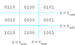
An outcode (or region code) is associated with each point (x,y) of the plane. This 4-bit code is assigned according to the following rules:
- bit 0 (rightmost) is 1 if the point is to the right of the region, that is x > xmax; it is 0 otherwise
- bit 1 is 1 if the point is left of the region (x < xmin)
- bit 2 is 1 if the point is above the region (y > ymax)
- bit 3 is 1 if the point is below the region (y < ymin)
The previous diagram shows the outcodes for each of the nine regions of the plane.
- Suppose that the outcode for point (x1,y1) is in the low order four bits of AL, that the outcode for point (x2,y2) is in the low order four bits of BL, and that other bits of these registers are reset to 0. Give a single 80x86 statement that will set ZF to 1 if the two points are both inside the rectangular region and to 0 otherwise. The value in AL or BL may be changed.
- Suppose that the outcode for point (x1,y1) is in the low order four bits of AL, that the outcode for point (x2,y2) is in the low order four bits of BL, and that other bits of these registers are reset to 0. Give a single 80x86 statement that will set ZF to 0 if the two points are both on the same side of the rectangular region. ("Both on the same side" means both right of x=xmax, both left of x=xmin, both above y=ymax,or both below y=ymin.) The value in AL or BL may be changed.
- Write a NEAR32 procedure setcode that returns the outcode for a point (x,y). Specifically, setcode has six word-size integer parameters: x, y, xmin, xmax, ymin, and ymax that are passed on the stack in the order given. Return the outcode in the low order four bits of the AL register, assigning 0 to each of the higher order bits in EAX.
Shift and Rotate Instructions
The logical instructions introduced in the previous section enable the assembly language programmer to set or clear bits in a word or byte stored in a register or memory. Shift and rotate instructions enable the programmer to change the position of bits within a doubleword, word, or byte. This section describes the shift and rotate instructions and gives examples of some ways they are used.
Shift instructions slide the bits in a location given by the destination operand to the left or to the right. The direction of the shift can be determined from the last character of the mnemonic—sal and shl are left shifts; sar and shr are right shifts. Shifts are also categorized as logical or arithmetic—shl and shr are logical shifts; sal and sar are arithmetic shifts. The difference between arithmetic and logical shifts is explained below. The table in Fig. 8.5 summarizes the mnemonics.

Figure 8.5: Shift instructions
The source code format of any shift instruction is
s- destination, count
There are three versions of the count operand. This operand can be the number 1, another number serving as a byte-size immediate operand, or the register specification CL. The original 8086/8088 CPU had only the first and third of these options.
An instruction having the format
s- destination, 1
causes a shift of exactly one position within the destination location. With the format
s- destination, immediate8
an immediate operand of 0 to 255 can be coded. However, most of the 80x86 family mask this operand by 000111112; that is they reduce it mod 32 before performing the shift. This makes sense because you cannot do over 32 meaningful shift operations to an operand no longer than a doubleword. In the final format,
s- destination, cl
the unsigned count operand is in the CL register. Again, most 80x86 CPUs reduce it modulo 32 before beginning the shifts.
Arithmetic and logical left shifts are identical; the mnemonics sal and shl are synonyms that generate the same object code. When a left shift is executed, the bits in the destination slide to the left and 0 bits fill in on the right. The bits that fall off the left are lost except for the very last one shifted off; it is saved in the carry flag CF. The sign flag SF, zero flag ZF, and parity flag PF are assigned values corresponding to the final value in the destination location. The overflow flag OF is undefined for a multiple-bit shift; for a single-bit shift (count=1) it is reset to 0 if the sign bit of the result is the same as the sign bit of the original operand value, and set to 1 if they are different. The auxiliary carry flag AF is undefined.
Arithmetic and logical right shifts are not the same. With both, the bits in the destination slide to the right and the bits that fall off the right are lost except for the very last one shifted off, which is saved in CF. For a logical right shift (shr) 0 bits fill in on the left. However, with an arithmetic right shift (sar) the original sign bit is used to fill in on the left. Therefore, for an arithmetic right shift, if the original operand represents a negative 2’s complement number, then the new operand will have leading 1 bits for each position shifted and will also be negative. As with left shifts, the values of SF, ZF, and PF depend on the result of the operation, and AF is undefined. The overflow flag OF is undefined for a multiple-bit shift. For a single-bit logical right shift shr, OF is reset to 0 if the sign bit in the result is the same as the sign bit in the original operand value, and set to 1 if they are different. (Notice that this is equivalent to assigning OF the sign bit of the original operand.) With a single-bit arithmetic right shift, sar, OF is always cleared—the sign bits of the original and new value are always the same.
Some hex calculators can directly do shift operations. Hand evaluation requires writing the operand in binary, shifting or regrouping the bits (filling in with 0s or 1s as appropriate), and then translating the new bit pattern back to hex. Things are a little simpler for a multiple-bit shift, which shifts four positions or some multiple of four positions; in this case each group of four bits corresponds to one hex digit, so one can think of shifting hex digits instead of bits. Here are a few examples that illustrate execution of shift instructions; each example begins with a word containing the hex value A9 D7 (1010 1001 1101 0111 in binary). The bit(s) shifted off are separated by a line in the original value. The bit(s) added are in bold in the new value.
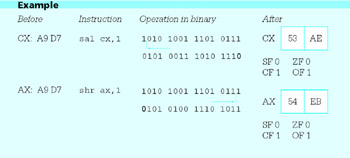
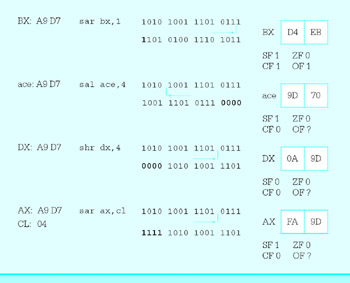
Figure 8.6 gives the number of clock cycles and number of bytes required using various operand types in shift instructions. All four types of shifts discussed so far, as well as the rotate instructions discussed below, share opcodes. The size of the destination and the type of the count operand are implied by the opcode. As with some other instructions, the second byte of the object code is used to choose among the different types of shifts and rotates, as well as between register and memory destinations. Notice that the single-bit shifts are faster than the multiple-bit shifts—often it is more time-efficient to use several single-bit shifts than one multiple-bit shift.
|
Clock Cycles |
Number of Bytes |
|||||
|---|---|---|---|---|---|---|
|
Destination Operand |
Count Operand |
386 |
486 |
Pentium |
Opcode |
|
|
register 8 |
1 |
3 |
3 |
1 |
2 |
D0 |
|
register 16/32 |
1 |
3 |
3 |
1 |
2 |
D1 |
|
memory byte |
1 |
7 |
4 |
3 |
2+ |
D0 |
|
memory word/doubleword |
1 |
7 |
4 |
3 |
2+ |
D1 |
|
register 8 |
immediate 8 |
3 |
2 |
1 |
3 |
C0 |
|
register 16/32 |
immediate 8 |
3 |
2 |
1 |
3 |
C1 |
|
memory byte |
immediate 8 |
7 |
4 |
3 |
3+ |
C0 |
|
memory word/doubleword |
immediate 8 |
7 |
4 |
3 |
3+ |
C1 |
|
register 8 |
CL |
3 |
3 |
4 |
2 |
D2 |
|
register 16/32 |
CL |
3 |
3 |
4 |
2 |
D3 |
|
memory byte |
CL |
7 |
4 |
4 |
2+ |
D2 |
|
memory word/doubleword |
CL |
7 |
4 |
4 |
2+ |
D3 |
Figure 8.6: Shift and rotate instructions
The shift instructions are quite primitive, but they have many applications. One of these is to do some multiplication and division operations. In fact, for processors without multiplication instructions, shift instructions are a crucial part of routines to do multiplication. Even with the 80x86 architecture, some products are computed more rapidly with shift operations than with multiplication instructions.
In a multiplication operation where the multiplier is 2, a single-bit left shift of the multiplicand results in the product in the original location. The product will be correct unless the overflow flag OF is set. It is easy to see why this works for unsigned numbers; shifting each bit to the left one position makes it the coefficient of the next higher power of two in the binary representation of the number. A single-bit left shift also correctly doubles a signed operand. In fact, one can use multiplication by 2 on a hex calculator to find the result of any single-bit left shift.
A single-bit right shift can be used to efficiently divide an unsigned operand by 2. Suppose, for example, that the EBX register contains an unsigned operand. Then the logical right shift shr ebx,1 shifts each bit in EBX to the position corresponding to the next lower power of two, resulting in half the original value. The original units bit is copied into the carry flag CF, and is the remainder for the division.
If EBX contains a signed operand, then the arithmetic right shift sar ebx,1 does almost the same job as an idiv instruction with a divisor of 2. The difference is that if the dividend is an odd negative number, then the quotient is rounded down; that is, it is one smaller than it would be using an idiv instruction. For a concrete example, suppose that the DX register contains FFFF and the AX register contains FFF7, so that DX-AX has the doubleword size 2’s complement representation for 9. Assume also that CX contains 0002. Then idiv cx gives a result of FFFC in AX and FFFF in DX; that is, a quotient of 4 and a remainder of 1. However, if FFFFFF7 is in EBX, then sar ebx,1 gives a result of FFFFFFFB in EBX and 1 in CF, a quotient of −5 and a remainder of +1. Both quotient-remainder pairs satisfy the equation
dividend = quotient*divisor + remainder
but with the −5 and +1 combination, the sign of the remainder differs from the sign of the dividend, contrary to the rule followed by idiv.
Instead of multiplying an operand by 2, it can be doubled by either adding it to itself or by using a left shift. A shift is sometimes slightly more efficient than addition and either is much more efficient than multiplication. To divide an operand by 2, a right shift is the only alternative to division and is much faster; however, the right shift is not quite the same as division by 2 for a negative dividend. To multiply or divide an operand by 4, 8, or some other small power of two, either repeated single-bit shifts or one multiple-bit shift can be used.
Shifts can be used in combination with other logical instructions to combine distinct groups of bits into a byte or a word or to separate the bits in a byte or word into different groups. The program shown in Fig. 8.7 prompts for an integer, uses the atod macro to convert it to 2’s complement form in the EAX register, and then displays the word in the EAX register as eight hexadecimal digits. To accomplish this display, eight groups of four bits must be extracted from the value in EAX. Each group of four bits represents a decimal value from 0 to 15, and each group must be converted to a character for display. This character is a digit 0 through 9 for integer value 0 (00002) through 9 (10012) or a letter A through F for integer value 10 (10102) through 15 (11112).
; program to display integer as 8 hex digits
; Author: R. Detmer
; Date: revised 11/97

.386
.MODEL FLAT

ExitProcess PROTO NEAR32 stdcall, dwExitCode:DWORD

include io.h ; header file for input/output

cr equ 0dh ; carriage return character
Lf equ 0ah ; line feed

.STACK 4096 ; reserve 4096-byte stack
.DATA ; reserve storage for data
prompt BYTE "Enter a number: ",0
number BYTE 20 DUP (?)
result BYTE cr,Lf,"The 2's complement representation is "
hexOut BYTE 8 DUP (?),cr,Lf,0

.CODE ; start of main program code
_start:
 output prompt ; prompt for number
 input number,20 ; read ASCII characters
 atod number ; convert to integer

 lea ebx,hexOut+7 ; address for last character
 mov ecx,8 ; number of characters
forCount: mov edx,eax ; copy pattern
 and edx,0000000fh ; zero all but last hex digit
 cmp edx,9 ; digit?
 jnle elseLetter ; letter if not
 or edx,30h ; convert to character
 jmp endifDigit
elseLetter: add edx,'A'-10 ; convert to letter
endifDigit:
 mov BYTE PTR [ebx],dl ; copy character to memory
 dec ebx ; point at next character
 shr eax,4 ; shift one hex digit right
 loop forCount ; repeat

 output result ; output label and hex value

 INVOKE ExitProcess, 0 ; exit with return code 0
PUBLIC _start ; make entry point public
END ; end of source code
Figure 8.7: Program to display an integer in hex
The eight characters are stored right to left in contiguous bytes of memory as they are generated; the EBX register is used to point at the destination byte for each character. The design for the middle of the program is
--------------
for count := 8 downto 1 loop
 copy EAX to EDX;
 mask off all but last 4 bits in EDX;

 if value in EDX ( 9
 then
 convert value in EDX to a character 0 through 9;
 else
 convert value in EDX to a letter A through F;
 end if;

 store character in memory at address in EBX;
 decrement EBX to point at next position to the left;
 shift value in EAX right four bits;
end for;
---------------
To implement this design, the instruction
and edx,0000000fh ; zero all but last hex digit
masks off all but the last four bits in EDX. The if is implemented by
 cmp edx,9 ; digit?
 jnle elseLetter ; letter if not
 or edx,30h ; convert to character
 jmp endifDigit
 elseLetter: add edx,'A'-10 ; convert to letter
 endifDigit:
A value from 0 to 9 is converted to the ASCII code for a digit using the or instruction; add edx,30h would work just as well here. To convert numbers 0A to 0F to the corresponding ASCII codes 41 to 46 for letters A to F, the value ’A’–10 is added to the number. This actually adds the decimal number 55, but the code used is clearer than add edx,55. The shr instruction shifts the value in EAX right four bits, discarding the hex digit that was just converted to a character.
Programming Exercise 2 of Section 7.4 asked for a procedure to do a job similar to that done by the program in Fig. 8.7. That procedure was to use the remainder upon division by 16 to produce a value corresponding to the rightmost hex digit. Notice that the shr and and instructions used in this example program are both easier to code and more efficient.
The shift instructions discussed above shift the bits of an operand in place, except that one bit affects the carry flag. The 80x86 architecture has two additional double shift instructions, shld and shrd. Each of these instructions has the format
sh-d destination, source, count
where the destination may be a word or a doubleword in a register or memory, the source is a word or doubleword in a register, and the count is either immediate or in CL. A shld instruction shifts the destination left exactly like a shl instruction, except that the bits shifted in come from the left end of the source operand. The source operand is not changed. A shrd instruction shifts the destination right exactly like a shr instruction, except that the bits shifted in come from the right end of the source operand. For both double shifts, the last bit shifted out goes to CF, and SF, ZF, and PF are given values corresponding to the result in the destination location. The overflow flag OF is left undefined by a double shift.
The following two examples illustrate double shift instructions. The one with shld shifts off the leading three hex digits (12 bits) of ECX, filling from the right with the leftmost three hex digits from EAX. The carry flag CF is 1 since the last bit shifted off was the rightmost bit of 3 (00112). The example using shrd shifts off the trailing two hex digits (8 bits) of ECX, filling from the left with the rightmost two hex digits from EAX. The carry flag CF is 0 since the last bit shifted off was the leftmost bit of 7 (01112).
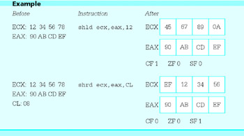
Figure 8.8 lists the various double shift instructions. The source operand is not shown since it is always a register 16 or register 32, the same size as the destination.
|
Clock Cycles |
Number of Bytes |
Opcode |
|||||
|---|---|---|---|---|---|---|---|
|
Destination Operand |
Count Operand |
386 |
486 |
Pentium |
shild |
shrd |
|
|
register 16/32 |
immediate 8 |
3 |
2 |
4 |
4 |
0F 04 |
0F AC |
|
memory word/doubleword |
immediate 8 |
7 |
4 |
4 |
4+ |
0F 04 |
0F AC |
|
register 16/32 |
CL |
3 |
3 |
4 |
3 |
0F 05 |
0F AD |
|
memory word/doubleword |
CL |
7 |
4 |
5 |
3+ |
0F 05 |
0F AD |
Figure 8.8: Double shift instructions
A double shift instruction can be used to get a slightly cleaner version of the program in Fig. 8.7. The following code generates the hex digits left-to-right instead of right to-left. Each time through the loop, a shld copies the leading hex digit from EAX into EDX.
 lea ebx,hexOut ; address for first character
 mov ecx,8 ; number of characters
forCount: shld edx,eax,4 ; get leading hex digit
 and edx,0000000fh ; zero all but last hex digit
 cmp edx,9 ; digit?
 jnle elseLetter ; letter if not
 or edx,30h ; convert to character
 jmp endifDigit
elseLetter: add edx,'A'-10 ; convert to letter
endifDigit:
 mov BYTE PTR [ebx],dl ; copy character to memory
 inc ebx ; point at next character
 shl eax,4 ; shift one hex digit left
 loop forCount ; repeat
Rotate instructions are very similar to single shift instructions. With shift instructions the bits that are shifted off one end are discarded while vacated space at the other end is filled by 0s (or 1s for a right arithmetic shift of a negative number). With rotate instructions the bits that are shifted off one end of the destination are used to fill in the vacated space at the other end.
Rotate instruction formats are the same as single shift instruction formats. A single-bit rotate instruction has the format
r- destination, 1
and there are two multiple-bit versions
 r- destination, immediate8
 r- destination, cl
The instructions rol (rotate left) and ror (rotate right) can be used for byte, word, or doubleword operands in a register or in memory. As each bit "falls off" one end, it is copied to the other end of the destination. In addition, the last bit copied to the other end is also copied to the carry flag CF. The overflow flag OF is the only other flag affected by rotate instructions. It is undefined for multibit rotates, and familiarity with its definition for single-bit rotate instructions is not needed in this book.
As an example, suppose that the DX register contains D25E and the instruction
rol dx, 1
is executed. In binary, the operation looks like

resulting in 1010 0100 1011 1101 or A4BD. The carry flag CF is set to 1 since a 1 bit rotated from the left end to the right.
Timings and opcodes for rotate instructions are identical to those for shift instructions. They are given in Fig. 8.6.
A rotate instruction can be used to give yet another version of the program in Fig. 8.7. This one produces the hex digits in a left-to-right order and has the advantage of leaving the value in EAX unchanged at the end since eight rotations, four bits each time, result in all bits being rotated back to their original positions.
 lea ebx,hexOut ; address for first character
 mov ecx,8 ; number of characters
forCount: rol eax,4 ; rotate first hex digit to end
 mov edx,eax ; copy all digits
 and edx,0000000fh ; zero all but last hex digit
 cmp edx,9 ; digit?
 jnle elseLetter ; letter if not
 or edx,30h ; convert to character
 jmp endifDigit
elseLetter: add edx,'A'-10 ; convert to letter
endifDigit:
 mov BYTE PTR [ebx],dl ; copy character to memory
 inc ebx ; point at next character
 loop forCount ; repeat
There is an additional pair of rotate instructions, rcl (rotate through carry left) and rcr (rotate through carry right). Each of these instructions treats the carry flag CF as if it were part of the destination. This means that rcl eax,1 shifts bits 0 through 30 of EAX left one position, copies the old value of bit 31 into CF and copies the old value of CF into bit 0 of EAX. The rotate through carry instructions obviously alter CF; they also affect OF, but no other flag. The opcodes for rotate through carry instructions are the same as the corresponding shift instructions and can be found in Fig. 8.6. However, the timings are different and are not given in this book.
Exercises 8.2
- For each part of this problem, assume the "before" values when the given instruction is executed. Give the requested "after" values.
Before
Instruction
After
(a)
AX: A8 B5
shl
ax, 1
AX, CF, OF
(b)
AX: A8 B5
shr
ax, 1
AX, CF, OF
(c)
AX: A8 B5
sar
ax, 1
AX, CF, OF
(d)
AX: A8 B5
rol
ax, 1
AX, CF
(e)
AX: A8 B5
ror
ax, 1
AX, CF
(f)
AX: A8 B5
CL: 04sal
ax, cl
AX, CF
(g)
AX: A8 B5
shr
ax, 4
AX, CF
(h)
AX: A8 B5
CL: 04sar
ax, cl
AX, CF
(i)
AX: A8 B5
CL: 04rol
ax, cl
AX, CF
(j)
AX: A8 B5
ror
ax, 4
AX, CF
(k)
AX: A8 B5
CF: 1rcl
ax, 1
AX, CF
(l)
AX: A8 B5
CF: 0rcr
ax, 1
AX, CF
(m)
AX: A8 B5
CX: FE 40shrd
ax,cx,4
AX, CF
(n)
AX: A8 B5
CX: FE 40shld
ax,cx,4
AX, CF
- Using clock cycles for the Pentium, compare the total number of clock cycles and bytes of object code for each of these alternative ways of dividing the unsigned integer in the EAX register by 32:
- mov edx,0 ; extend value to doubleword mov ebx,32 ; divisor div ebx ; value div 32
- shr eax,1 ; divide by 2 shr eax,1 ; divide by 2 shr eax,1 ; divide by 2 shr eax,1 ; divide by 2 shr eax,1 ; divide by 2
- shr eax,5 ; divide by 32
- Using clock cycles for the Pentium, compare the total number of clock cycles and bytes of object code for each of these alternative ways of multiplying the value in the EAX register by 32:
- mov ebx,32 ; multiplier mul ebx ; value * 32
- imul eax,32 ; value * 32
- shl eax,1 ; multiply by 2 shl eax,1 ; multiply by 2 shl eax,1 ; multiply by 2 shl eax,1 ; multiply by 2 shl eax,1 ; multiply by 2
- shl eax,5 ; multiply by 32
- Suppose that each of value1, value2, and value3 references a byte in memory and that an unsigned integer is stored in each byte. Assume that the first value is no larger than 31 so that it has at most five significant bits and at least three leading 0 bits. Similarly assume that the second value is no larger than 15 (four significant bits) and the third value is no larger than 127 (seven bits).
- Give code to pack all three of these numbers into a 16-bit word in the AX register, copying the low order five bits from value1 to bits 11–15 of AX, the low order four bits from value2 to bits 7–10 of AX, and the low-order seven bits from value3 into bits 0–6 of AX.
- Give code to unpack the 16 bit number in the AX register into fivebit, four-bit, and seven-bit numbers, padding each value with zeros on the left to make eight bits, and storing the resulting bytes at value1, value2, and value3 respectively.
- The instructions
mov ebx, eax ; value
shl eax, 1 ; 2*value
add eax, ebx ; 3*value
multiplies the value in EAX by 3. Write similar code sequences that use shift and addition instructions to efficiently multiply by 5, 7, 9, and 10.
Programming Exercises 8.2
- Write a NEAR32 procedure binaryString that converts a 32-bit integer to a string of exactly 32 characters representing its value as a binary number. The procedure will have two parameters, passed on the stack:
- the number
- the address of the destination string
The procedure will remove parameters from the stack and must modify no register. Use a rotate instruction to extract the bits one at a time, left-to-right, recalling that jc or jnc instructions look at the carry bit. (This exercise is the same as Programming Exercise 3 in Section 7.4 except for the method of producing the bits.)
- An eight-bit number can be represented using three octal digits. Bits 7 and 6 determine the left octal digit, which is never larger than 4, bits 5, 4, and 3 the middle digit, and bits 2, 1, and 0 the right digit. For instance, 110101102 is 11 010 1102 or 3268. The value of a 16-bit number is represented in split octal by applying the 2–3–3 system to the high-order and low-order bytes separately. Write a NEAR32 procedure split-Octal which converts an 16-bit integer to a string of exactly six characters representing the value of the number in split octal. The procedure will have two parameters, passed on the stack:
- the number
- the address of the destination string
The procedure will remove parameters from the stack and must modify no register.
Converting an ASCII String to a 2 s Complement Integer
The atoi and atod macros have been used to scan an area of memory containing an ASCII representation of an integer, producing the corresponding word-length 2's complement integer in the EAX register. These macros and the procedures they call are very similar. This section uses atod as an example.
The atod macro expands into the following sequence of instructions.
 lea eax,source ; source address to EAX
 push eax ; source parameter on stack
 call atodproc ; call atodproc(source)
These instructions simply call procedure atodproc using a single parameter, the address of the string of ASCII characters to be scanned. The EAX register is not saved by the macro code since the result is to be returned in EAX. The actual source identifier is used in the expanded macro, not the name source.
The actual ASCII to 2's complement integer conversion is done by the procedure atodproc. The assembled version of this procedure is contained in the file IO.OBJ. Source code for atodproc is shown in Fig. 8.9. The procedure begins with standard entry code. The flags are saved so that flag values that are not explicitly set or reset as promised in the comments can be returned unchanged. The popf and pop instructions at AToDExit restore these values; however, the word on the stack that is popped by popf will have been altered by the body of the procedure, as discussed below.
; atodproc(source)
; Procedure to scan data segment starting at source address, interpreting
; ASCII characters as an integer value that is returned in EAX.

; Leading blanks are skipped. A leading - or + sign is acceptable.
; Digit(s) must immediately follow the sign (if any).
; Memory scan is terminated by any nondigit, and the address of
; the terminating character is in ESI.

; The following flags are affected:
; AC is undefined
; PF, SF, and ZF reflect sign of number returned in EAX. ; CF reset to 0
; OF set to indicate error. Possible error conditions are:
; - no digits in input
; - value outside range -2,147,483,648 to 2,147,483,647
; (EAX) will be 0 if OF is set.

atodproc PROC NEAR32
 push ebp ; save base pointer
 mov ebp, esp ; establish stack frame
 sub esp, 4 ; local space for sign
 push ebx ; Save registers
 push ecx
 push edx
 pushf ; save flags

 mov esi,[ebp+8] ; get parameter (source addr)

WhileBlankD: cmp BYTE PTR [esi],' ' ; space?
 jne EndWhileBlankD ; exit if not
 inc esi ; increment character pointer
 jmp WhileBlankD ; and try again
EndWhileBlankD:

 mov eax,1 ; default sign multiplier
IfPlusD: cmp BYTE PTR [esi],'+' ; leading + ?
 je SkipSignD ; if so, skip over
IfMinusD: cmp BYTE PTR [esi],'-' ; leading - ?
 jne EndIfSignD ; if not, save default +
 mov eax,-1 ; -1 for minus sign
SkipSignD: inc esi ; move past sign
EndIfSignD:
 mov [ebp-4],eax ; save sign multiplier
 mov eax,0 ; number being accumulated
 mov cx,0 ; count of digits so far

WhileDigitD: cmp BYTE PTR [esi],'0' ; compare next character to '0'
 jl EndWhileDigitD ; not a digit if smaller than '0'
 cmp BYTE PTR [esi],'9' ; compare to '9'
 jg EndWhileDigitD ; not a digit if bigger than '9'
 imul eax,10 ; multiply old number by 10
 jo overflowD ; exit if product too large
 mov bl,[esi] ; ASCII character to BL
 and ebx,0000000Fh ; convert to single-digit integer
 add eax,ebx ; add to sum
 jc overflowD ; exit if sum too large
 inc cx ; increment digit count
 inc esi ; increment character pointer
 jmp WhileDigitD ; go try next character
EndWhileDigitD:

 cmp cx,0 ; no digits?
 jz overflowD ; if so, set overflow error flag
; if value is 80000000h and sign is '-', want to return 80000000h (-2^32)

 cmp eax,80000000h ; 80000000h ?
 jne TooBigD?
 cmp DWORD PTR [ebp-4],-1 ; multiplier -1 ?
 je ok1D ; if so, return 8000h

TooBigD?: test eax,eax ; check sign flag
 jns okD ; will be set if number > 2^32 - 1

overflowD: pop ax ; get flags
 or ax,0000100001000100B ; set overflow, zero & parity flags
 and ax,1111111101111110B ; reset sign and carry flags
 push ax ; push new flag values
 mov eax,0 ; return value of zero
 jmp AToDExit ; quit

okD: imul DWORD PTR [ebp-4] ; make signed number
ok1D: popf ; get original flags
 test eax,eax ; set flags for new number
 pushf ; save flags
AToDExit: popf ; get flags
 pop edx ; restore registers
 pop ecx
 pop ebx
 mov esp, ebp ; delete local variable space
 pop ebp
 ret 4 ; exit, removing parameter
atodproc ENDP
Figure 8.9: ASCII to doubleword integer conversion
The first job of atodproc is to skip leading spaces, if any. This is implemented with a straightforward while loop. Note that BYTE PTR [esi] uses register indirect addressing to reference a byte of the source string. Following the while loop, ESI points at some nonblank character.
The main idea of the procedure is to compute the value of the integer by implementing the following left-to-right scanning algorithm.
value :=0;
while pointing at code for a digit loop
 multiply value by 10;
 convert ASCII character code to integer;
 add integer to value;
 point at next byte in memory;
end while;
This design works for an unsigned number; a separate multiplier is used to give the correct sign to the final signed result. The second job of the procedure, after skipping blanks, is to store this multiplier, 1 for a positive number or 1 for a negative number. The multiplier, stored in local variable space on the stack, is given the default value 1 and changed to 1 if the first nonblank character is a minus sign. If the first nonblank character is either plus or a minus sign, then the address in ESI is incremented to skip over the sign character.
Now the main design is executed. The value is accumulated in the EAX register. If multiplication by 10 produces an overflow, then the result is too large to represent in EAX. The jc overflowD instruction transfers control to the code at overflowD that takes care of all error situations.
To convert a character to a digit, the character is loaded into the BL register and the instruction and ebx,0000000Fh clears all bits except the low-order four in the EBX register. Thus, for example, the ASCII code 3716 for 7 becomes 00000007 in the EBX register. If adding the digit to the accumulated value produces a carry, the sum is too large for EAX; the jc instruction transfers control to overflowD.
The main loop terminates as soon as ESI points at any character code other than one for a digit. Thus an integer is terminated by a space, comma, letter, null, or any nondigit. In order to determine if a valid integer has been entered, the main loop keeps a count of decimal digits in the CX register. When the loop terminates, this count is checked. If it is zero, there was no digit and the jz instruction jumps to overflowD for error handling. There is no need to check for too many digits; this would already have been caught by overflow in the main loop.
If the accumulated value in the AX register is larger than 8000000016(2,147,483,648 as an unsigned number), then the magnitude of the number is too great to be represented in doubleword-length 2's complement form. If it is equal to 8000000016, then the multiplier must be −1 since −2,147,483,648 can be represented (as 8000000016), but +2,147,483,648 is too large. The next section of code checks for 800000016 in EAX and a multiplier of −1; in this case the work is almost done. Otherwise, the instruction test eax,eax is used to see if the accumulated value is larger than 800000016; the sign bit will be 1 for a value of this magnitude.
If any of the error conditions occur, the instructions starting at overflowD are executed. The original flags are popped into the AX register. The bit corresponding to the overflow flag is set to 1 to indicate an error, and a value of 00000000 will be returned in EAX; other flags are set or reset to correspond to the zero value. The instruction
or ax,0000100001000100b ; set overflow, zero & parity flags
sets bit 11 (the position of overflow flag), bit 6 (zero flag), and bit 2 (parity flag). The zero flag is set since the result returned will be zero; the parity flag is set since 0000000016 has even parity (an even number of 1 bits). The instruction
and ax,1111111101111110b ; reset sign and carry flags
clears bit 7 (sign flag) since 00000000 is not negative and bit 0 (carry), which is always cleared. The bit pattern resulting from these or and and instructions is pushed back on the stack to be popped into the flags register by popf before exiting the procedure.
When no exceptional condition exists, an imul instruction finds the product of the unsigned value and the multiplier (+1) giving the correct signed result. Flag values are set in this normal situation by using popf to recover the original flag values; test eax,eax clears CF and OF and assigns appropriate values to PF, SF, and ZF. The new flag values are then pushed back on the stack with another pushf to be recovered by the normal popf in the exit code. The test instruction leaves AC undefined; this is why the comments at the beginning of the procedure mention AC.
Exercises 8.3
- The code for atodproc includes
TooBigD?: test eax,eax ; check sign flag
 jns okD ; will be set if number > 2^32 - 1
An alternative sequence would be
TooBigD?: cmp eax,80000000h ; EAX < 2,147,483,648
 jb okD ; OK if so
Compare the number of clock cycles and number of bytes of object code for the test and the cmp instructions.
- The procedure atodproc checks for zero digits in the number it is converting, but not for too many digits. Show why this is unnecessary by tracing the code for 100,000,000,000, the smallest possible 11-digit number. (Another valid reason not to limit the number of digits is that any number of leading zeros would be valid.)
Programming Exercises 8.3
- Write a NEAR32 procedure hexToInt that has a single parameter passed on the stack, the address of a string. This procedure will be similar to atodproc except that it will convert a string of characters representing an unsigned hexadecimal number to a doubleword-length 2's complement integer in EAX. The procedure should skip leading blanks and then accumulate a value until a character that does not represent a hex digit is encountered. (Valid characters are 0 through 9, A through F, and a through f.) If there are no hex digits or the result is too large to fit in EAX, then return 0 and set OF; these are the only possible errors. Clear OF if no error occurs. In all cases set SF, ZF, and PF according to the value returned in EAX and clear CF.
The Hardware Level Logic Gates
Digital computers contain many integrated circuits and many of the components on these circuits are logic gates. A logic gate performs one of the elementary logical operations described in Section 8.1: and, or, xor, or not. Each type of gate has a simple diagram that represents its function. These diagrams are pictured in Fig. 8.10, with inputs shown on the left and output on the right.
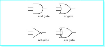
Figure 8.10: Logic Gates
These simple circuits operate by getting logic 0 or 1 inputs and putting the correct value on the output. For example, if the two inputs of the or circuit are 0 and 1, then the output will be 1. Logic values 0 and 1 are often represented by two distinct voltage levels.
These simple circuits are combined to make the complex circuits that perform a computer’s operations. For example, Fig. 8.11 pictures a half adder circuit. The logic values at inputs x and y of this circuit can be thought of as two bits to add. The desired results are 0+0=0, 1+0=1, and 0+1=1, each with a carry of 0, and 1+1=0 with a carry of 1. These are exactly the results given by a half adder circuit.
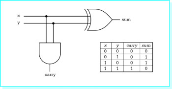
Figure 8.11: Half adder circuit
Exercises 8.4
Addition of multibit numbers is performed much like decimal addition learned in grade school; pairs of bits are added starting with the right-most pair, but after the first pair, you must also add the carry from the previous result. To do this takes a series of full adder circuits. One full adder circuit has three inputs x, y, and carry in, and two outputs, sum and carry out.
- Make a chart similar to the one in Fig. 8.11 showing the inputs and outputs for a full adder. The chart will have five columns (x, y, carry in, sum, and carry out) and eight rows below the header row.
- Draw a full adder circuit. Hint: Use two half adders and an or gate to combine their carry outputs.
- Use three full adders and a half adder to draw a circuit that can add two four bit numbers. This circuit will have eight inputs (four pairs of bits) and five outputs (four sum bits and a carry bit). For simplicity, you can draw each adder or half adder as a block diagram, without showing all its gates.
Summary
This chapter has explored the various 80x86 instructions that allow bits in a byte, word, or doubleword destination to be manipulated. The logical instructions and, or, and xor perform Boolean operations using pairs of bits from a source and destination. Applications of these instructions include setting or clearing selected bits in a destination. The not instruction takes the one's complement of each bit in its destination operand, changing each 0 to a 1 and each 1 to a 0. The test instruction is the same as the and instruction except that it only affects flags; the destination operand is unchanged.
Shift instructions move bits left or right within a destination operand. These instructions come in single-bit and multiple-bit versions. Single-bit shifts use 1 for the second operand; multiple-bit versions use CL or an immediate value for the second operand and shift the destination the number of positions specified. Vacated positions are filled by 0 bits in all single shift operations except for the arithmetic right shift of a negative number, for which 1 bits are used. Shift instructions can be used for efficient, convenient multiplication or division by 2, 4, 8 or some higher power of two. Double shift instructions get bits to shift in from a source register.
Rotate instructions are similar to shift instructions. However, the bit that falls off one end of the destination fills the void on the other end. Shift or rotate instructions can be used in combination with logical instructions to extract groups of bits from a location or to pack multiple values into a single byte or word.
The atod macro generates code that calls the procedure atodproc. This procedure scans a string in memory, skipping leading blanks, noting a sign (if any), and accumulating a doubleword integer value as ASCII codes for digits are encountered. Logical instructions are used in several places in the procedure.
Logic gates are the primitive building blocks for digital computer circuits. Each gate performs one of the elementary Boolean operations.
Preface
- Representing Data in a Computer
- Parts of a Computer System
- Elements of Assembly Language
- Basic Instructions
- Branching and Looping
- Procedures
- String Operations
- Bit Manipulation
- The Assembly Process
- Floating-Point Arithmetic
- Decimal Arithmetic
- Input/Output
- Appendix A Hexadecimal/ASCII conversion
- Appendix B Useful MS-DOS Commands
- Appendix C MASM 6.11 Reserved Words
- Appendix D 80x86 Instructions (by Mnemonic)
- Appendix E 80x86 Instructions (by Opcode)
EAN: 2147483647
Pages: 113
