5D: Pick Up the Camera
D Pick Up the Camera
What if you could pick up a camera and move it around a world of objects that were flat and two dimensional, yet were related to one another and to a virtual camera in 3D space? As was touched upon near the end of the previous chapter, that's pretty much the dimensional model After Effects offers you. You might call it a "2.5D" world, comprised of objects that can exist anywhere but have no depth of their own.
There are a lot of fun, stylized ways to play around with 3D in After Effects, but there are also ways in which you can get the After Effects 3D camera to match the behavior of a real camera, if you understand how they are similar and how they differ. Therefore it's worth taking a closer look at how 3D works in After Effects, and how its various featuresthe camera, lights, and shading optionscorrespond to their real world counterparts.
Understand the After Effects Camera
You can begin using 3D in After Effects without setting a camerajust toggle a layer to 3D and voila, its properties contain three axes instead of twobut it's a little bit like driving a race track using a car with an automatic transmission: You can't maneuver properly, and before long you'll probably run into something hard.
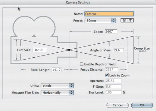
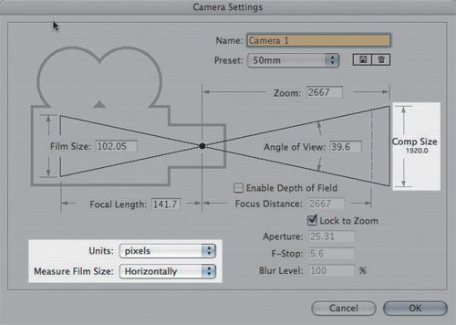
Furthermore, when you set a camera, you encounter an area of the After Effects user interface that includes a physical diagram: the Camera Settings dialog (Figure 9.1). If you understand it, the diagram and its settings tell you virtually everything you need to know about how the After Effects camera views the 3D world.
Figure 9.1. Visual artists love visual user interfaces, and the Camera Settings dialog is one of the few to include a diagram. That's a good thing because it also contains a lot of settings that most users find a bit abstract. Here are the default settings for a 50 mm preset, which happens to be the setting that introduces no change of lens angle from a flat 2D view.
Notes
One confusing point about After Effects' virtual camera is its use of lens settings that correspond to those of still SLR (single lens reflex) cameras, which really aren't used a whole lot in film and video production.
Close-Up: 7.0 View Options
Version 7.0 makes working in 3D easier than previous versions. At the bottom of the Composition viewer is a View Layout pull-down menu allowing you to select multiple views in a single viewer. These can be used for 2D compositions, but their real use is to allow you to see several 3D angles simultaneously. Click in each viewer and you'll see the 3D View pop-up change its context to that view; small yellow triangles in the corners show you which view is active.
At the bottom of the View Layout options is a Share View Options toggle; this causes all viewers to use the same Fast Previews settings (for OpenGL and so on).
In Grid and Guide options you can choose to display 3D Reference Axes; although After Effects does not display full 3D grids, these can help orient you.
Finally, if you're having difficulty seeing wireframes for cameras and lights, check the settings for Camera Wireframes and Spotlight Wireframes in the Composition panel menu's View Options.
Lens Settings
The default After Effects camera employs the 50 mm preset (listed in the Preset pull-down menu in the Camera Settings dialog; you see this when you create a new camera, or when you choose Layer > Camera Settings). Switching all of your layers to 3D, then adding this camera does not change the appearance of the scene whatsoever, whereas all other lengths do.
Unfortunately, "50 mm" is a "virtually meaningless" term because virtual space doesn't contain millimeters any more than it contains kilograms, parsecs, or bunny rabbits. Virtual space, as you know, is typically measured in pixels.
Any physical camera has a corresponding lens length that would be considered neither long nor wide; its size varies with the size of the image gathering medium or device. Such a lens will capture a scene without shifts in perspective and distortion, featuresnot all of them displeasingassociated with lenses that are wider or longer, tending respectively more toward the fisheye or telephoto perspective (Figures 9.2 through 9.4).
Figure 9.2. The extreme wide or fisheye lens pointed inside an evenly proportioned 3D box. Note that the "long" look of the box is created by this "wide" lens, which tends to create very strange proportions at this extreme. A physical lens with anything like this angle would include extremely distorted lens curvature.
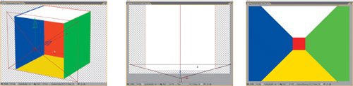
Figure 9.3. A telephoto lens (using the 200 mm setting) pushes items together in depth space, shortening the distance between the front and back of the box dramatically.
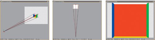
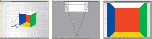
Figure 9.4. The default lens (50 mm setting). If the Z Position value is the exact inverse of the Zoom value, and all other settings are at the default, this is the view you get, and it matches the appearance of setting no After Effects camera whatsoever.
50 millimeters is the median lens length of a 35 mm SLR still camera, as has been used for professional photography for decades. SLR cameras are familiar to a wider audience (including After Effects developers, evidently) than professional film or video cameras.
On a feature film, your source would much more likely have been shot with a 35 mm motion picture camera shooting Academy ratio, a completely different beast that just so happens to employ a 35 mm default lens length. Had your footage been shot with a miniDV camera, however, the tiny CCD would employ an equally tiny default lens length of around 4 millimeters. The appearance of different lens lengths is directly related to the size of the backplate or video pickup, the area where the image is projected inside the camera. The smaller the film size (or CCD size), the shorter the default lens.
Notes
How many movies have been shot predominantly using an SLR camera? Not many; La Jetée, a 1962 science fiction film by Chris Marker was the inspiration for Terry Gilliam's movie 12 Monkeys, and consists entirely of still shots that were presumably taken with a 35 mm camera.
Notes
There is an optional fifth numerical field in the Camera Settings diagram, indirectly related to the other four: Focus Distance, which is enabled by checking Enable Depth of Field. This corresponds to a camera's aperture setting; I'll touch on it separately later.
My point is that millimeters don't mean a whole lot unless they're measuring the actual physical lens of an actual physical camera. The only setting in the Camera Settings that truly, universally applies, whether images were shot in IMAX or HDV or created in a 3D animation package, is the Angle of View.
Real-World Camera Settings
The most important question is: How do the After Effects camera's settings correspond to those of a camera in the physical world? In other words, suppose you know a camera's settings, how do you put them to use in your shot?
Look again at the diagram in Camera Settings (Figure 9.1). Four numerical fieldsFilm Size, Focal Length, Zoom, and Angle of Vieware oriented around two triangles sharing a common hypotenuse. Using a physical camera with a prime lens, these values are all fixed. With a zoom lens, the Film Size is of course fixed, but Zoom and Focal Length can be adjusted, resulting in a change in the Angle of View. These four settings, then, are interrelated and interdependent, as the diagram implies.
The After Effects camera simulates this setup: Change one of Angle of View, Zoom, or Focal Length, and the other two values change proportionally, while Film Size remains fixed. Film Size is useful only to emulate a specific camera (more about that in a moment).
Lengthen the lens, and Focal Length increases as Angle of View decreases. A physical telephoto lens really is longer from lens to back plate, and adjusting its zoom does make the lens longer or shorter. The only feature that would make this diagram any clearer would be for it to articulate, visually displaying the changing Angle of View settings as clearly as can be seen (particularly in the top views) in Figures 9.2 through 9.4.
Make Your Adjustments
The only two settings that must hold your focus (pun only slightly intended) are Zoom (for animation) and Angle of View (to match source where that measurement is available). The others, Film Size and Focal Length, make sense only relative to those two.
Angle of View is the actual radius, in degrees, that the camera sees. The setting corresponds directly to real-world cameras, and Angle of View is a setting you will see in other computer graphics programs, so it can be matched precisely in 3D animation software.
The Zoom value is the distance of the camera lens, in pixels, from the plane of focus (generally, the subject being photographed). By default, a new camera employs a Z Position value equivalent to the negative of its Zoom value. This retains framing of all layers at the default Z position of 0.0 (the appearance doesn't change switching from 2D to 3D). The plane of focus icon represents an area the size of the composition (Figure 9.5) so it can be used to frame a shot.
Figure 9.5. It's easy to overlook the highlighted settings. Comp Size (at the right) is the horizontal size, in pixels; it changes according to how Units and Measure Film Size settings are set (left). Comp Size appears to display a vertical measurement (the diagram does not change according to the Measure Film Size setting).
There are several cases in which it is ideal that the Zoom value is in pixels. It makes for easy reference when measuring depth of field effects, and it makes it possible to link the position of the camera and the zoom together via expressions for depth of field and related effects (discussed later).
Emulate a Real Camera
And how do you put all of this knowledge to work? You probably have one of two goals: Either you're matching the camera settings of source footage so that your elements appear to have been taken with that camera, or you're creating a shot from scratch but want it to appear as if shot with a particular camera and lens. Here are some of the things you have to consider:
- Depth of Field: Is everything in the shot in focus, or does the shot require a narrow depth of field with elements in the foreground and background drifting out of focus?
- Zoom or push: If you are moving in or out on the shot, which type of camera move is it (discussed further in the section called "Move the Camera")?
- Motion blur and shutter angle: These settings are not controlled via the 3D camera. (They're composition settingsfor more, review Chapter 2, "The Timeline.")
- Lens angle and distortion: The perspective and parallax of layers in 3D space change according to the angle of the lens used to view them. Real lenses introduce lens distortion, curvature that can be especially apparent with wide angle lenses (hence the term "fisheye lens"). The After Effects camera does not employ a lens and so, does not generate lens distortion, but it can be recreated (see "Optics Compensation").
- Exposure: New to After Effects 7.0 is the Exposure control, which appears in the Composition viewers of a 32 bpc project. Exposure in After Effects is similar, yet completely different from that of a real camera. Suffice it to say that exposure is not related to the 3D camera, and you should see Chapter 11, "Film, HDR, and 32 Bit Per Channel Composition," for theoretical understanding, and Chapter 12, "Working with Light," for practical examples.
Notes
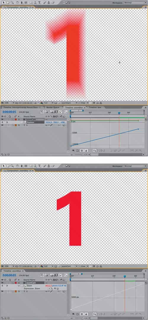
The movement of the camera itself can generate motion blur (Figures 9.6a and b). The key is that any layers to be blurred by the motion of the camera have Motion Blur toggled on.
Figures 9.6a and b. Motion blur is activated for a stationary object (a), but only the camera moves. Zooming the camera instead generates no motion blur (b).
One specific piece of information that can help you match existing footage is a camera report, a record of the settings used when the footage was taken. If the crew included a camera assistant (or equivalent), this information was probably logged at the shoot.
Make Use of a Camera Report
If you know the type of camera and the focal length used for your shots, you have enough information to match the lens of that camera with your After Effects camera.
Tip
A potentially easier alternative to the listed steps, for those who like using expressions, is to use the following expression on the camera's Zoom property:
FocalLength = 35 // change to your value, in mm
hFilmPlane = 24.892 //change to your film
size, in mm
this_comp.width*(Focal Length/hFilmPlane)
Table 9.1 details the sizes of some typical film formats. If your camera is on the list, and you know the focal length, use these to match the camera via Camera Settings. The steps are
|
1. |
Set Measure Film Size to Horizontally. |
|
2. |
Set Units to Inches. |
|
3. |
Enter the number from the Horizontal column of the chart that corresponds to the source film format. |
|
4. |
Set Units to Millimeters. |
|
5. |
Enter the desired Focal Length. |
|
FORMAT |
HORIZONTAL |
VERTICAL |
|---|---|---|
|
Full Aperture Camera Aperture |
0.980 |
0.735 |
|
Scope Camera Aperture |
0.864 |
0.732 |
|
Scope Scan |
0.825 |
0.735 |
|
2:1 Scope Projector Aperture |
0.838 |
0.700 |
|
Academy Camera Aperture |
0.864 |
0.630 |
|
Academy Projector Aperture |
0.825 |
0.602 |
|
1.66 Projector Aperture |
0.825 |
0.497 |
|
1.85 Projector Aperture |
0.825 |
0.446 |
|
VistaVision Aperture |
0.991 |
1.485 |
|
VistaVision Scan |
0.980 |
1.470 |
|
16 mm Camera Aperture |
0.404 |
0.295 |
|
Super-16 Camera Aperture |
0.493 |
0.292 |
|
HD Full 1.78 |
0.378 |
0.212 (Full Aperture in HD 1.78) |
|
HD 90% 1.78 |
0.340 |
0.191 (90% Safe Area used in HD 1.78) |
|
HD Full 1.85 |
0.378 |
0.204 (Full Aperture in HD 1.85) |
|
HD 90% 1.85 |
0.340 |
0.184 (90% Safe Area used in HD 1.85) |
|
HD Full 2.39 |
0.3775 |
0.158 (Full Aperture in HD 2.39) |
|
HD 90% 2.39 |
0.340 |
0.142 (90% Safe Area used in HD 2.39) |
|
Courtesy Stu Maschwitz/The Orphanage |
||
Once the Angle of View matches the footage, any objects that you track in (perhaps using techniques described in Chapter 8, "Effective Motion Tracking") will maintain position in the scene as the shot progresses. It's vital to get this right if your camera is going to move during the shot, and especially if a wide or long lens was used.
Lens Distortion
If a virtual camera is set with a wide lens angle, the software simply samples a wider (and taller) area of the scene, as in Figure 9.2. This dramatically changes the perspective of 3D space, but it does not actually distort objects the way a real camera lens does because a digital camera uses no lens. A virtual camera can widen the view area and scan it in a linear fashion.
A lens curves light to project it properly on the camera backplate. A real camera cannot simply widen its view area, which is essentially fixed. It can only "see" what is perpendicular to the surface of the lens glass, so it combines a convex lens and a short lens length to pull a more disparate (wider) range of view.
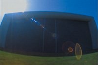
At the extremes, this causes lens distortion that is easily visible; items in the scene known to contain straight lines don't appear straight at all, but bent in a curve (Figure 9.7). In a fisheye lens shot, it's as if the screen has been inflated like a balloon. It's rare, but not unprecedented, for a shot in a movie to look like this (for example, the droid's point of view in a certain well-known science fiction film).
Figure 9.7. The almost psychedelic look of lens distortion at its most extreme; even the flare caused by the front lens element is extremely aberrated. An equivalently wide lens using the After Effects 3D camera would not cause straight lines (the ground plane, the building outline) to appear curved.
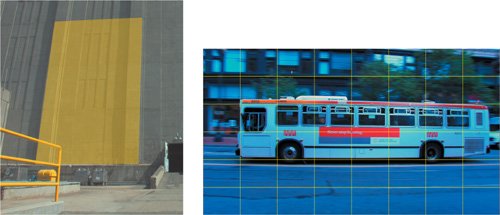
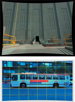
As you gain experience evaluating shots, you may notice that many shots that aren't as extreme as a fisheye perspective contain a degree of lens distortion. You might notice that motion tracks from one side of the frame don't seem to apply equally well at the other side of the frame, proportions go out of whack, and things don't quite line up as they should (Figures 9.8a and b).
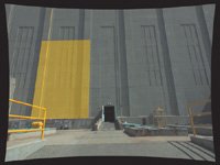
Figures 9.8a and b. In a close-up area of a shot (a), an attempt to corner-pin a yellow solid to the side of the building fails; it is not possible to make all four corners and edges line up properly. Grid lines over footage of the bus clearly show that it is distortednote the bowed appearance of straight lines on the pavement, and the background building (b). (Building examples courtesy Stu Maschwitz; bus footage courtesy Pixel Corps.)
There's no way to introduce lens distortion directly to a 3D camera, but the Optics Compensation effect (Professional version only) is designed to add or remove it in 2D. Figure 9.9 shows this effect in action. Increasing the Field of View makes the affected layer more fisheyed in appearance; to correct a shot coming in with lens distortion, check Reverse Lens Distortion and raise the Field of View (FOV) value.
Figures 9.9a and b. Distortion removal takes place in a composition larger than the source; the padding allows space for the corners of the image. In the building image, the Beam effect serves as a virtual plumb line (a); with the bus, it is clear from the grid that distortion has been corrected (b).
This process is not exactly scientific because the Field of View settings don't correspond to measurable phenomena, such as the Lens Angle. You must locate what should be a straight line in the scene and adjust the setting until you're happy with the match. The specific workflow is
- Having identified that there is lens distortion on a background plate to which you must add foreground elements (as in Figure 9.8a), drop the background into a new composition that is at least 20% larger than the plate to accommodate stretching the corners.
- Add an adjustment layer above the plate layer, and apply Optics Compensation to that layer. Check Reverse Lens Distortion and raise the Field of View (FOV) setting until lines that should appear straight in your image look straight.
- Add a Beam effect below the Optics Compensation effect (so that it is unaffected by Optics Compensation). Make its Inside Color and Outside Color settings match (using any color you'll be able to see easily), and align the Starting Point and Ending Point along an apparently straight line near the edge of frame. Fine-tune the Field of View setting a little more until the line is plumb (Figures 9.9a and b).
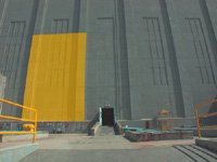
- Precompose all of these layers and set this new composition as a guide layer. In Figure 9.10, you can see that the corner pin is now successful. You must now match the distortion of the source shot.
Figure 9.10. Over the undistorted background plate, you can freely position, animate, and composite elements as if everything were normal. Note that the perspective is still that of a very wide angle lens, but without the curvature.
- Create a new master composition containing the background plate and the laid-out foreground elements. Copy Optics Compensation from the adjustment layer where you undistorted the background and paste it to the foreground element but turn off Reverse Lens Distortion. The exact distortion of your background is applied to your foreground elements, which now match up (Figure 9.11).
Figure 9.11. The Optics Compensation effect with Reverse Lens Distortion unchecked restores the original look of the frame; the foreground distorts to match the background, and features now line up properly.
You have tricked After Effects into compositing in distort-o-vision. Here is an original Stu Maschwitz haiku to sum up the process:
undistort, derive
reunite distorted things
with an untouched plate
Mixing 2D and 3D
Use of a 3D camera in an effects situation typically entails mixing 3D elements and a 2D plate background. This is no big deal, as After Effects doesn't demand an exclusively 2D or a 3D world; elements of both can be layered together. This is a huge advantage as long as you're clear about how it works:
- A 2D background remains in place no matter how you move the camera (as in the motion tracking examples using a 3D camera in the previous chapter).
- 2D adjustment layers set to comp size and default position affect the whole composition, including 3D layers.
- Foreground layers from 3D programs imported with 3D camera tracking data can be manipulated in 3D while remaining rendered 2D elements.
Everybody wins.
Where are the gotchas of this approach? They are all special cases:
- A 2D layer can use a 3D track matte, and vice versa. Beware of combining a 3D track matte and a 3D layer: It's rarely (if ever) what you want, and maintaining the positional relationship relative to the camera is usually tricky. At least one layer typically should be unaffected by camera motion.
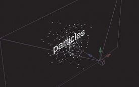
- Certain effects emulate 3D perspective by making use of the After Effects camera. Typically (and paradoxically) these operate on 2D layers only. Examples include Trapcode's Particular and 3D Stroke (Figure 9.12).
Figure 9.12. Incredibly, particles generated by Trapcode Particular occupy true 3D space, as is evident in a perspective view. Paradoxically, the effect is applied to a 2D layer. It calculates 3D data internally using the After Effects camera as a reference, an elegant workaround for the fact that 3D layers in After Effects are always flat planes.
- Precomposing a set of 3D layers effectively causes them to collectively behave like a single 2D layer. They no longer interact in 3D space unless you enable Collapse Transformations for the precomp layer. Doing so bypasses the camera in the embedded composition, and uses the 3D position of the precomposed layers. (More on this in Chapter 4, "Optimizing Your Projects.")
So go ahead, freely mix 2D and 3D layersjust remember these tips if things start to seem funky.
Tip
Always keep in mind where the audience's attention is focusedyou can employ the magician's technique, misdirection, to get away with something you shouldn't. Robert Rodríguez was only able to make his debut film, El Mariachi, with meager funds by knowing that if the audience were to notice its many continuity errors, the story would have been considered a failure.
Storytelling and the Camera |
Section I. Working Foundations
The 7.0 Workflow
- The 7.0 Workflow
- Workspaces and Panels
- Making the Most of the UI
- Settings: Project, Footage, Composition
- Previews and OpenGL
- Effects & Presets
- Output: The Render Queue
- Study a Shot like an Effects Artist
The Timeline
- The Timeline
- Organization
- Animation Methods
- Keyframes and The Graph Editor
- Uber-mastery
- Transform Offsets
- Motion Blur
- Manipulating Time Itself
- In Conclusion
Selections: The Key to Compositing
- Selections: The Key to Compositing
- The Many Ways to Create Selections
- Compositing: Science and Nature
- Alpha Channels and Premultiplication
- Masks
- Combining Multiple Masks
- Putting Masks in Motion
- Blending Modes: The Real Deal
- Track Mattes
Optimizing Your Projects
- Optimizing Your Projects
- Navigating Multiple Compositions
- Precomposing and Nesting
- Adjustment and Guide Layers
- Understanding Rendering Order
- Optimizing After Effects
- Onward to Effects
Section II. Effects Compositing Essentials
Color Correction
Color Keying
- Color Keying
- Good Habits and Best Practices
- Linear Keyers and Hi-Con Mattes
- Blue-Screen and Green-Screen Keying
- Understanding and Optimizing Keylight
- Fixing Typical Problems
- Conclusion
Rotoscoping and Paint
- Rotoscoping and Paint
- Articulated Mattes
- Working Around Limitations
- Morphing
- Paint and Cloning
- Conclusion
Effective Motion Tracking
- Effective Motion Tracking
- The Essentials
- Optimizing Tracking Using 3D
- Extending a Track with Expressions
- Tracking for Rotoscoping
- Using 3D Tracking Data
- Conclusion
Virtual Cinematography
- Virtual Cinematography
- 5D: Pick Up the Camera
- Storytelling and the Camera
- Camera Blur
- The Role of Grain
- Film and Video Looks
- Conclusion
Expressions
- Expressions
- Logic and Grammar
- Muting Keyframes
- Linking Animation Data
- Looping Animations
- Smoothing and Destabilizing
- Offsetting Layers and Time
- Conditionals and Triggers
- Tell Me More
Film, HDR, and 32 Bit Compositing
- Film, HDR, and 32 Bit Compositing
- Details
- Film 101
- Dynamic Range
- Cineon Log Space
- Video Gamma Space
- Battle of the Color Spaces
- Floating Point
- 32 Bits per Channel
- Conclusion
Section III. Creative Explorations
Working with Light
- Working with Light
- Light Source and Direction
- Creating a Look with Color
- Backlighting, Flares, Light Volume
- Shadows and Reflected Light
- HDR Lighting
- Conclusion
Climate: Air, Water, Smoke, Clouds
- Climate: Air, Water, Smoke, Clouds
- Particulate Matter
- Sky Replacement
- The Fog, Smoke, or Mist Rolls In
- Billowing Smoke
- Wind
- Water
- Conclusion
Pyrotechnics: Fire, Explosions, Energy Phenomena
- Pyrotechnics: Fire, Explosions, Energy Phenomena
- Firearms
- Sci-Fi Weaponry
- Heat Distortion
- Fire
- Explosions
- In a Blaze of Glory
Learning to See
Index
EAN: 2147483647
Pages: 157
