Service-oriented business process design (a step-by-step process)

Designing the process of a service-oriented solution really just comes down to properly interpreting the business process requirements you have collected and then implementing them accurately. The trick, though, is to also account for all possible variations of process activity. This means understanding not just what can go wrong, but how the process will respond to unexpected or abnormal conditions.

Historically, business processes were designed by analysts using modeling tools that produced diagrams handed over to architects and developers for implementation. The workflow diagram and its accompanying documentation were the sole means of communicating how this logic should be realized within an automated solution. While diligent analysis and documentation, coupled with open minded and business-aware technical expertise, can lead to a successful collaboration of business and technical team members, this approach does leave significant room for error.

This gap is being addressed by operational business modeling languages, such as WS-BPEL. Modeling tools exist, allowing technical analysts and architects to graphically create business process diagrams that represent their workflow logic requirements, all the while auto-generating WS-BPEL syntax in the background.

These tools typically require that the user possess significant knowledge of the WS-BPEL language. However, more sophisticated tools, geared directly at business analysts, already are emerging, removing the prerequisite of having to understand WS-BPEL to create WS-BPEL process definitions.

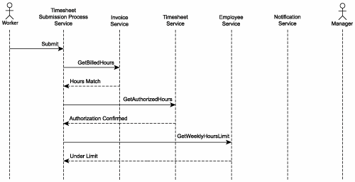
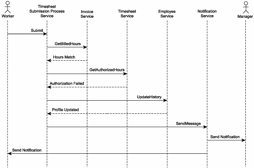
The result is a diagram on the front-end that expresses the analysts' vision of the process and a computer executable process definition on the back-end that can be handed over to architects and developers for immediate (and not-open-to-interpretation) implementation (Figure 16.2).

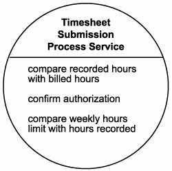
Figure 16.2. A concrete definition of a process service designed using a process modeling tool.

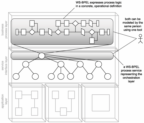
When operational, the WS-BPEL process is appropriately represented and expressed through a process service within the service interface layer. This process service effectively establishes the orchestration service sub-layer, responsible for governing and composing business and application layers.

16.3.1. Process description

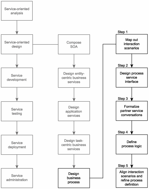
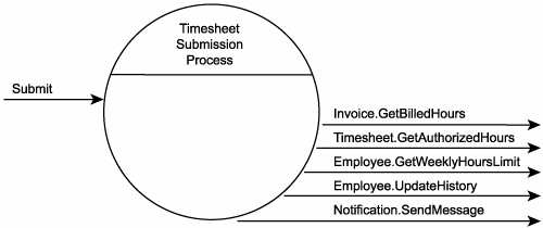
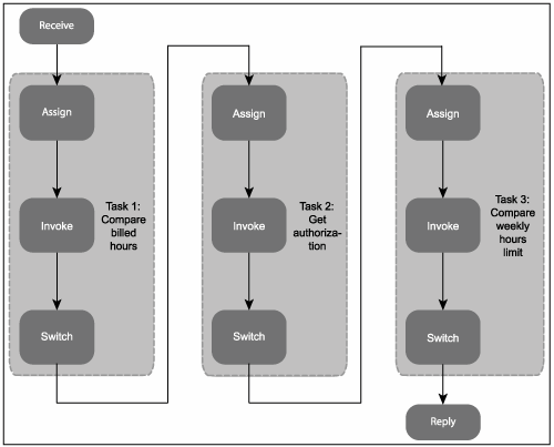
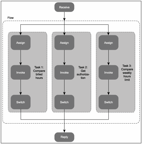
The following step-by-step design process (Figure 16.3) provides some high-level guidance for how to approach the creation of a WS-BPEL process definition. The steps are similar to those used by the Task-centric business service design process described in Chapter 15, except for one important detail.

Figure 16.3. A high-level process for designing business processes.

When we designed a task-centric service, we simply produced a service interface capable of handling anticipated message exchanges. The details of the workflow logic were deferred to the design and development of the underlying application logic. When designing a WS-BPEL process, this workflow logic is abstracted into a separate process definition. Therefore, the design of workflow details is addressed at this stage, along with the definition of the process service interface.

The examples used to demonstrate each step are intentionally simple so that the basic WS-BPEL element descriptions we just covered in the previous section can be easily understood. When designing more complex workflow logic, a more detailed and elaborate design process is required.

Business process design is the last step in our overall service-oriented design process. This means that, for the most part, the application and business services required to carry out the process logic will have already been modeled and designed as we begin.

Case Study

The original workflow logic for the TLS Timesheet Submission Process (Figure 16.4) that was created during the modeling exercise in Chapter 12 is revisited as TLS analysts and architects embark on designing a corresponding WS-BPEL process definition.

Figure 16.4. The original TLS Timesheet Submission Process.


As part of completing the previous service design processes, TLS now has the inventory of service designs displayed in Figure 16.5. In our previous case study examples, we only stepped through the creation of the Employee Service. The other service designs are provided here to help demonstrate the WS-BPEL partner links we define later on.

Figure 16.5. Service designs created so far.


TLS also digs out the original composition diagram (Figure 16.6) that shows how these four services form a hierarchical composition, spearheaded by the Timesheet Submission Process Service TLS plans to build.

Figure 16.6. The original service composition defined during the service modeling stage.


Finally, TLS architects revive the original service candidate created for the Timesheet Submission Process Service (Figure 16.7).

Figure 16.7. The Timesheet Submission Process Service candidate.


With all of this information in hand, TLS proceeds with the business process design.


Step 1: Map out interaction scenarios

By using the following information gathered so far, we can define the message exchange requirements of our process service:

  • Available workflow logic produced during the service modeling process in Chapter 12.
  • The process service candidate created in Chapter 12.
  • The existing service designs created in Chapter 15.

This information now is used to form the basis of an analysis during which all possible interaction scenarios between process and partner services are mapped out. The result is a series of processing requirements that will form the basis of the process service design we proceed to in Step 2.

Case Study

TLS maps out a series of different service interaction scenarios using activity diagrams. Following are examples of two scenarios.

Figure 16.8 illustrates the interaction between services required to successfully complete the Timesheet Submission Process with a valid timesheet submission. Note that in this scenario, the Notification Service is not used.

Figure 16.8. A successful completion of the Timesheet Submission Process.


Figure 16.9 demonstrates a scenario in which the timesheet document is rejected by the Timesheet Service. This occurs because the timesheet failed to receive proper authorization.

Figure 16.9. A failure condition caused by an authorization rejection.


The result of mapping out interaction scenarios establishes that the process service has one potential client partner service and four potential partner services from which it may need to invoke up to five operations (Figure 16.10).

Figure 16.10. The incoming and outgoing request messages expected to be processed by the Timesheet Submission Process Service.


Step 2: Design the process service interface

Now that we understand the message exchange requirements, we can proceed to define a service definition for the process service. When working with process modeling tools, the process service WSDL definition will typically be auto-generated for you. However, you also should be able to edit the source markup code or even import your own WSDL definition.

Either way, it is best to review the WSDL definition being used and revise it as necessary. Here are some suggestions:

  • Document the input and output values required for the processing of each operation, and populate the types section with XSD schema types required to process the operations. Move the XSD schema information to a separate file, if required.
  • Build the WSDL definition by creating the portType (or interface) area, inserting the identified operation constructs. Then add the necessary message constructs containing the part elements that reference the appropriate schema types. Add naming conventions that are in alignment with those used by your other WSDL definitions.
  • Add meta information via the documentation element.
  • Apply additional design standards within the confines of the modeling tool.

There is less opportunity to incorporate the other steps from the service design processes described in Chapter 15. For example, applying the service-orientation principle of statelessness is difficult, given that process services maintain state so that other services don't have to.

Case Study

It looks like the Timesheet Submission Process Service interface will be pretty straightforward. It only requires one operation used by a client to initiate the process instance (Figure 16.11).

Figure 16.11. Timesheet Submission Process Service design.


Following is the corresponding WSDL definition:

Example 16.18. The abstract service definition for the Timesheet Submission Process Service.

xmlns:plnk=
 "http://schemas.xmlsoap.org/ws/2003/05/partner-link/">


 Initiates the Timesheet Submission Process.


 name="tns:TimesheetSubmissionInterface"/>


Note the bolded plnk:parnterLinkType construct at the end of this WSDL definition. This is added to every partner service.


Step 3: Formalize partner service conversations

We now begin our WS-BPEL process definition by establishing details about the services with which our process service will be interacting.

The following steps are suggested:

  1. Define the partner services that will be participating in the process and assign each the role it will be playing within a given message exchange.
  2. Add parterLinkType constructs to the end of the WSDL definitions of each partner service.
  3. Create partnerLink elements for each partner service within the process definition.
  4. Define variable elements to represent incoming and outgoing messages exchanged with partner services.

This information essentially documents the possible conversation flows that can occur within the course of the process execution. Depending on the process modeling tool used, completing these steps may simply require interaction with the user-interface provided by the modeling tool.

Case Study

Now that the Timesheet Submission Process Service has an interface, TLS can begin to work on the corresponding process definition. It begins by looking at the information it gathered in Step 1. As you may recall, TLS determined the process service as having one potential client partner service and four potential partner services from which it may need to invoke up to five operations.

Roles are assigned to each of these services, labeled according to how they relate to the process service. These roles are then formally defined by appending existing service WSDL definitions with a partnerLinkType construct.

Example 16.19 shows how the Employee Service definition (as designed in Chapter 15) is amended to incorporate the WS-BPEL partnerLinkType construct and its corresponding namespace.

Example 16.19. The revised Employee service definitions construct.

xmlns:plnk=
 "http://schemas.xmlsoap.org/ws/2003/05/partner-link/">
 ...


This is formalized within the process definition through the creation of partnerLink elements that reside within the partnerLinks construct. TLS analysts and architects work with a process modeling tool to drag and drop partnerLink objects, resulting in the following code being generated.

Example 16.20. The partnerLinks construct containing partnerLink elements for each of the process partner services.

<partnerLinks>
 <partnerLink name="client"
 partnerLinkType="bpl:TimesheetSubmissionProcessType"
 myRole="TimesheetSubmissionProcessServiceProvider"/>
 <partnerLink name="Invoice"
 partnerLinkType="inv:InvoiceType"
 partnerRole="InvoiceServiceProvider"/>
 <partnerLink name="Timesheet"
 partnerLinkType="tst:TimesheetType"
 partnerRole="TimesheetServiceProvider"/>
 <partnerLink name="Employee"
 partnerLinkType="emp:EmployeeType"
 partnerRole="EmployeeServiceProvider"/>
 <partnerLink name="Notification"
 partnerLinkType="not:NotificationType"
 partnerRole="NotificationServiceProvider"/>
partnerLinks>
 

Next the input and output messages of each partner service are assigned to individual variable elements, as part of the variables construct. A variable element also is added to represent the Timesheet Submission Process Service Submit operation that is called by the HR client application to kick off the process.

Example 16.21. The variables construct containing individual variable elements representing input and output messages from all partner services and for the process service itself.

<variables>
 <variable name="ClientSubmission"
 messageType="bpl:receiveSubmitMessage"/>
 <variable name="EmployeeHoursRequest"
 messageType="emp:getWeeklyHoursRequestMessage"/>
 <variable name="EmployeeHoursResponse"
 messageType="emp:getWeeklyHoursResponseMessage"/>
 <variable name="EmployeeHistoryRequest"
 messageType="emp:updateHistoryRequestMessage"/>
 <variable name="EmployeeHistoryResponse"
 messageType="emp:updateHistoryResponseMessage"/>
 <variable name="InvoiceHoursRequest"
 messageType="inv:getBilledHoursRequestMessage"/>
 <variable name="InvoiceHoursResponse"
 messageType="inv:getBilledHoursResponseMessage"/>
 <variable name="TimesheetAuthorizationRequest"
 messageType="tst:getAuthorizedHoursRequestMessage"/>
 <variable name="TimesheetAuthorizationResponse"
 messageType="tst:getAuthorizedHoursResponseMessage"/>
 <variable name="NotificationRequest"
 messageType="not:sendMessage"/>
variables>
 

If you check back to the Employee Service definition TLS designed in Chapter 15, you'll notice that the name values of the message elements correspond to the values assigned to the messageType attributes in the previously displayed variable elements.


Step 4: Define process logic

Finally, everything is in place for us to complete the process definition. This step is a process in itself, as it requires that all existing workflow intelligence be transposed and implemented via a WS-BPEL process definition.

Case Study

The TLS team now creates a process definition that expresses the original workflow logic and processing requirements, while accounting for the two service interaction scenarios identified earlier. The remainder of this example explores the details of this process definition.

A visual representation of the process logic about to be defined in WS-BPEL syntax is displayed in Figure 16.12. (Note that this diagram illustrates the process flow that corresponds to the success condition expressed by the first of the two activity diagrams created during Step 1.)

Figure 16.12. A descriptive, diagrammatic view of the process definition logic.


Note

The complete process definition is several pages long and therefore is not displayed here. Instead, we highlight relevant parts of the process, such as activities and fault handling. The entire process definition is available for download at www.serviceoriented.ws.


Established first is a receive element that offers the Submit operation of the Timesheet Submission Process Service to an external HR client as the means by which the process is instantiated.

Example 16.22. The receive element providing an entry point by which the process can be initiated.

<receive xmlns=
 "http://schemas.xmlsoap.org/ws/2003/03/business-process/"
 name="receiveInput"
 partnerLink="client"
 portType="tns:TimesheetSubmissionInterface"
 operation="Submit"
 variable="ClientSubmission"
 createInstance="yes"/>
 

By tracing the receive element's operation value back to the original Timesheet Submission Service WSDL, you can find out that the expected format of the input data will be a complete timesheet document, defined in a separate XSD schema document. When a document is received, it is stored in the ClientSubmission process variable.

As per the interaction logic defined in the initial activity diagram (Step 1), the first activity the process is required to perform is to interact with the Invoice Service to compare the hours submitted on the timesheet with the hours actually billed out to the client. The Invoice Service will not perform the comparison for the process; instead, it will simply provide the amount of hours for a given invoice identified by an invoice number.

Before invoking the Invoice Service, the assign construct first needs to be used to extract values from the original timesheet document, which now is stored in the ClientSubmission variable. Specifically, the customer ID and date values (encapsulated in the BillingInfo element) are required as input for the Invoice Service's GetBilledHours operation.

Example 16.23. The assign and copy constructs hosting a from element that retrieves customer billing information from the message stored in the ClientSubmission variable and a to element that is used to assign these values to the InvoiceHoursRequest variable.

<assign name="GetInvoiceID">
 <copy>
 <from variable="ClientSubmission" part="payload"
 query="/TimesheetType/BillingInfo"/>
 <to variable="InvoiceHoursRequest"
 part="RequestParameter"/>
 copy>
assign>
 

Now that the InvoiceHoursRequest variable contains the required input values for the Invoice Service's GetBilledHours operation, the invoke element is added.

Example 16.24. The invoke element containing a series of attributes that provide all of the information necessary for the orchestration engine to locate and instantiate the Invoice Service.

<invoke name="ValidateInvoiceHours"
 partnerLink="Invoice"
 operation="GetBilledHours"
 inputVariable="InvoiceHoursRequest"
 outputVariable="InvoiceHoursResponse"
 portType="inv:InvoiceInterface"/>
 

Upon invoking the Invoice Service, a response message is received from the GetBilledHours operation. As defined in the invoke element's outputVariable attribute, this message is stored in the InvoiceHoursResponse variable.

If the value in this variable matches the value in the timesheet document, then the hours have been validated. To determine this, the switch construct is used. A child case construct is added, which contains a condition attribute in which the conditional logic is defined.

Example 16.25. The switch construct hosting a case element that uses the getVariableData function within its condition attribute to compare hours billed against hours recorded.

<switch name="BilledHoursMatch">
 <case condition=
 "getVariableData('InvoiceHoursResponse',
 'ResponseParameter') !=
 getVariableData('input','payload',
 '/tns:TimesheetType/Hours/...')">
 
 case>
switch>
 

If the condition (billed hours is not equal to invoiced hours) is not met, then the hours recorded on the submitted timesheet document are considered valid, and the process moves to the next step.

If the condition is met, a fault is thrown using the throw element. This circumstance sends the overall business activity to the faultHandlers construct, which resides outside of the main process flow. This is the scenario portrayed in the second of the two activity diagrams assembled by TLS in Step 1 and is explained later in this example.

What TLS has just defined is a pattern consisting of the following steps:

  1. Use the assign, copy, from, and to elements to retrieve data from the ClientSubmission variable and assign it to a variable containing an outbound message.
  2. Use the invoke element to interact with a partner service by sending it the outbound message and receiving its response message.
  3. Use the switch and case elements to retrieve and validate a value from the response message.
  4. Use the throw element to trigger a fault, if validation fails.

A good part of the remaining process logic repeats this pattern, as illustrated in the original process overview displayed back in Figure 16.12. For brevity, this part of the process is summarized here:

  • Use the assign construct to copy the TimesheetID value from the ClientSubmission variable to the TimesheetAuthorizationRequest variable that is used via the invoke element as the input message for the GetAuthorizedHours operation of the Timesheet service. The authorization result is extracted from the response message within the switch construct, and if positive, the process proceeds to the next step. If authorization fails, a fault is raised using the tHRow element.
  • Using the assign element, the EmployeeID value is retrieved from the ClientSubmission variable and placed in the EmployeeHoursRequest variable. This variable becomes the request message used by the invoke element to communicate with the Employee Service's GetWeeklyHoursLimit operation. The response message from that operation is submitted to the condition attribute of the case element within the switch construct. The result is a determination as to whether the employee exceeded the allowed maximum hours per week. If the value was exceeded, the process jumps to the faultHandlers construct.

That pretty much sums up the primary processing logic of the TLS Timesheet Submission Process. Although the initial requirements do not call for it, the process flow could end with a reply element that responds to the initial client that instantiated the process.

Now it's time to turn our attention to the second scenario (portraying a failure condition) mapped out in the other activity diagram from Step 1. To accommodate this situation, TLS architects choose to implement a faultHandlers construct, as shown here:

Example 16.26. The faultHandlers construct used in this process.

<faultHandlers>
 
 
 ...
 
 
faultHandlers>
 

Although individual catch elements could be used to trap specific faults, TLS simply employs a catchAll construct, as all three thrown faults require the same exception handling logic.

The tasks performed by the fault handler routine are:

  1. Update employee profile history.
  2. Send notification to manager.
  3. Send notification to employee.

To implement these three tasks, the same familiar assign and invoke elements are used. Figure 16.13 shows an overview of the fault handling process logic.

Figure 16.13. A visual representation of the process logic within the faultHandlers construct.


Note that the following, abbreviated markup code samples reside within the sequence child construct of the parent faultHandlers construct established in the previous example.

First up is the markup code for the "Update employee profile history" task.

Example 16.27. Two copy elements used to populate the EmployeeHistoryRequest message.


 <copy>
 
 
 copy>
 <copy>
 
 
 copy>


To perform the first task of updating the employee history, the fault handler routine uses an assign construct with two copy constructs. The first retrieves the EmployeeID value from the ClientSubmission variable, while the latter adds a static employee profile history comment.

The invoke element then launches the Employee Service (used previously for its GetWeeklyHoursLimit operation) and submits the EmployeeHistoryRequest message to its UpdateHistory operation to log the profile history comment.

The next block of markup code takes care of both the remaining "Send notification" tasks.

Example 16.28. The last activities in the process.


The faultHandlers construct contains two more assign + invoke element pairs. Both use the Notification Service's SendMessage operation, but in different ways. The first assign construct extracts the ManagerID value from the ClientSubmission variable, which is then passed to the Notification Service. It is the sole parameter that the service subsequently uses to look up the corresponding e-mail address for the notification message.

Next, the second assign construct retrieves the EmployeeID value from the same ClientSubmission variable, which the Notification Service ends up using to send a message to the employee.

The very last element in the construct, terminate, halts all further processing.


Step 5: Align interaction scenarios and refine process (optional)

This final, optional step encourages you to perform two specific tasks: revisit the original interaction scenarios created in Step 1 and review the WS-BPEL process definition to look for optimization opportunities.

Let's start with the first task. Bringing the interaction scenarios in alignment with the process logic expressed in the WS-BPEL process definition provides a number of benefits, including:

  • The service interaction maps (as activity diagrams or in whatever format you created them) are an important part of the solution documentation and will be useful for future maintenance and knowledge transfer requirements.
  • The service interaction maps make for great test cases and can spare testers from having to perform speculative analysis.
  • The implementation of the original workflow logic as a series of WS-BPEL activities may have introduced new or augmented process logic. Once compared to the existing interaction scenarios, the need for additional service interactions may arise, leading to the discovery of new fault or exception conditions that then can be addressed back in the WS-BPEL process definition.

Secondly, spending some extra time to review your WS-BPEL process definition is well worth the effort. WS-BPEL is a multi-feature language that provides different approaches for accomplishing and structuring the same overall activities. By refining your process definition, you may be able to:

  • Consolidate or restructure activities to achieve performance improvements.
  • Streamline the markup code to make maintenance easier.
  • Discover features that were previously not considered.

Case Study

TLS analysts and architects revise their original activity diagrams so that they accurately reflect the manner in which process logic was modeled using WS-BPEL. However, in reviewing the interaction scenarios and their current process model, they recognize a key refinement that could significantly optimize the process definition they just created.

Here's a recap of the three primary tasks performed by this process:

  1. Validate recorded timesheet hours with hours billed on invoice.
  2. Confirm authorization of timesheet.
  3. Ensure that hours submitted are equal to or less than the weekly hours limit.

As shown in Figure 16.14, the process has been designed so that these three tasks execute sequentially (one begins only after the former ends). Although this approach is useful when dependencies between tasks exist, it is determined that there are no such dependencies between these three tasks.

Figure 16.14. Sequential, synchronous execution of process activities.


Therefore, they all can be executed at the same time, the only condition being that the process cannot continue beyond these tasks until all have completed. This establishes a parallel processing model.

By utilizing the WS-BPEL flow construct, TLS can model the three activities to execute concurrently (Figure 16.15), resulting in significant performance gains. It is further determined that the same form of optimization can be applied to the process logic within the fault handling routine, as neither of those activities have inter-dependencies either.

Figure 16.15. Concurrent execution of process activities using the flow construct.


Finally, while reviewing the structure of the fault handling routine, a further refinement is suggested. Because the last two activities invoke the same Notification Service, they can be collapsed into a while construct that loops twice through the invoke element.

SUMMARY OF KEY POINTS

  • Designing a process service requires the design of the service interface and the design of the process definition.
  • Process definition is typically accomplished using a graphical modeling tool, but familiarity with WS-BPEL language basics is often still required.
  • There are numerous ways in which WS-BPEL process definitions can be streamlined and optimized.


Introduction

Case Studies

Part I: SOA and Web Services Fundamentals

Introducing SOA

The Evolution of SOA

Web Services and Primitive SOA

Part II: SOA and WS-* Extensions

Web Services and Contemporary SOA (Part I: Activity Management and Composition)

Web Services and Contemporary SOA (Part II: Advanced Messaging, Metadata, and Security)

Part III: SOA and Service-Orientation

Principles of Service-Orientation

Service Layers

Part IV: Building SOA (Planning and Analysis)

SOA Delivery Strategies

Service-Oriented Analysis (Part I: Introduction)

Service-Oriented Analysis (Part II: Service Modeling)

Part V: Building SOA (Technology and Design)

Service-Oriented Design (Part I: Introduction)

Service-Oriented Design (Part II: SOA Composition Guidelines)

Service-Oriented Design (Part III: Service Design)

Service-Oriented Design (Part IV: Business Process Design)

Fundamental WS-* Extensions

SOA Platforms

Appendix A. Case Studies: Conclusion


Service-Oriented Architecture. Concepts, Technology, and Design
Service-Oriented Architecture (SOA): Concepts, Technology, and Design
ISBN: 0131858580
EAN: 2147483647
Year: 2004
Pages: 150
Authors: Thomas Erl

Flylib.com © 2008-2020.
If you may any questions please contact us: flylib@qtcs.net