Understanding Relationships
We've dealt with the first two steps of the design process now: the sorting out of entities and attributes. After you have what you think is a decent draft of a set of entities and attributes, the next thing to do is to start considering how these entities relate to one another. You need to become familiar with the fundamental types of entity relationships, and also with a simple notation for representing relationships graphically in a diagram.
Representing Relationships in a Diagram
Consider a system that stores information about farmers and pigs, among other things. Farmers and pigs are each entities, and these two entities have a direct relationship, in that each pig ties back to a single farmer.
There's a name for the farmer-pig relationship. It's called a one-to-many relationship, meaning that for each farmer there may be any number of pigs. "One farmer," as we usually put it, "can have many pigs."
Now you can expand on the entity-relationship notation. You already have a graphical shorthand for depicting the entities and attributes in a database system. Next you should add some conventions for showing the relationships among them. Each entity can be represented by a box, as before, and each relationship can be represented by a line that indicates the relationship type. In this simple notation, you'd depict the relationship between farmers and pigs along the lines of what's shown in Figure 5.4.
Figure 5.4. Entity-relationship notation for a database that stores information about farmers and pigs.
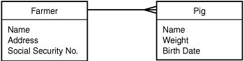
Notice that the line between the two entities that depicts their relationship branches out where it touches the Pig entity. In a one-to-many relationship, this fork or branch indicates the "many" end of the relationship. So this notation tells us that one farmer may be linked to many pigs. If the fork were on the other end, this would imply that one pig could be associated with many farmers, which would be a very different assertion about the data we're trying to model.
Relationship Types
Those simple graphical conventions are the foundation of what you need in order to draw your entity-relationship diagrams. Another important concept is an understanding of the different relationship types you could encounter. You need to reckon with four types: the one-to-one relationship, which is a rare case you probably won't encounter much; the one-to-many and many-to-one relationships (the latter is simply a one-to-many relationship looked at from the other direction); and the many-to-many relationship, a common but more complicated relationship to which we'll need to devote special attention.
We'll consider each of these relationship types in turn, and show how to represent them in the ERD notation.
One-to-One Relationships
The one-to-one relationship type is rather rare in practice. For example, consider a dataset concerning children and their birth records. Let's say that for now, you've decided that children and birth records should represent separate entities.
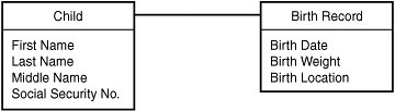
In a standard analysis sequence, after you've decided on entities and attributes, you'll start to ask questions about relationships. What's the relationship between children and birth records? Can one child have many birth records? No, each child is born only once. And can one birth record pertain to more than one child? Again, probably not. So the relationship between a child and a birth record appears to be one-to-one. You can depict that as shown in Figure 5.5.
Figure 5.5. This ERD shows the one-to-one relationship between children and birth records. A single line with no "crow's-foot" is used.
It's rare to let the two sides of a one-to-one relationship stand as separate entities. Instead, you'll often fold one of the entities into the other. In this case, you might decide to move all the attributes of a birth record into the Child entity and get rid of Birth Record as a separate entity.
One-to-Many Relationships
We've already devoted some attention to the one-to-many relationship. The relationships of a customer to sales, of a farmer to pigs, and of a worker to timesheets are all examples of one-to-many relationships. And you've seen the crow's-foot notation for indicating these relationships, in which the fork notation indicates the "many" side of the relationship.
There's another piece of terminology for one-to-many relationships that's helpful to know. You'll frequently see the entity that represents the "one" side of the relationship referred to as the parent entity, whereas the "many" side is often referred to as the child entity. If you hear a database architect blurt out a reference to a "child" table, odds are she's referring to the entity on the "many" side of a one-to-many relationship.
Many-to-One Relationships
There's no difference at all between the concepts of a one-to-many and a many-to-one relationship. They're the same idea, just seen from different points of view. If the relationship between customers and sales is one-to-many, then it's equally true that the relationship between sales and customers is many-to-one. Customer is the parent of Sale, Sale is the child of Customer. These statements are equivalent. Figure 5.6 shows the Customer-Sale relationship. Whether you choose to describe this as a one-to-many or a many-to-one depends on which side you start from in your description. The relationship of a customer to a sale is one-to-many; the relationship of a sale to a customer is many-to-one. One-to-many and many-to-one are two sides of the same coin; a relationship can't be one without being the other.
Figure 5.6. The Customer-Sale relationship drawn as both a one-to-many and a many-to-one relationship.

Many-to-Many Relationships
Consider the relationship between actors and movies. One actor may play roles in many movies, and one movie involves roles played by many actors. So each actor can relate to many movies, and each movie may be associated with many actors. This is a classic many-to-many relationship. You can depict it as shown in Figure 5.7.
Figure 5.7. Entity-relationship notation for a many-to-many relationship.

Many-to-many relationships are extremely common in relational database systems. Here are examples of some other many-to-many relationships:
- Attorney-Case One attorney may serve on many cases, and one case may involve many attorneys.
- Player-Game One player may play in many games, and one game involves many players.
- Product-Invoice One invoice may contain orders for many products, and one product may be ordered on many different invoices.
- Student-Class One student may participate in many classes, and one class may have many students enrolled.
You can probably think of your own examples pretty easily as well.
Many-to-many relationships are a bit trickier than the others to actually implement in real life. When we get to the details of how to build a FileMaker database based on an ERD, you'll see the specific techniques you need to bring a many-to-many relationship to life in FileMaker. For now, though, we'll just use the ERD as an analysis tool, and not worry about implementation.
Relationship Cardinality
You've seen how to filter a process description into a list of entities and their attributes, and you've seen a useful language for describing the relationships between those entities. So far, in describing these relationships, we've been mainly concerned with the question "How many?" How many purchases can relate to a customer? One, or many? And how many customers can participate in a purchase?
The answers to these questions tell you into which of the three (or four) relationship types a given relationship falls. This information is sometimes referred to as the cardinality of the relationship. Cardinality specifies whether a relationship is one-to-one, one-to-many, many-to-one, or many-to-many.
Relationship Optionality |
Part I: Getting Started with FileMaker 8
FileMaker Overview
- FileMaker Overview
- FileMaker and Its Marketplace
- Introduction to Database Software
- FileMaker Deployment Options
- Whats New in FileMaker Pro 8
Using FileMaker Pro
- Getting Started
- Working in FileMaker Pro
- Troubleshooting
- FileMaker Extra: Becoming a FileMaker Pro Power User
Defining and Working with Fields
- Defining and Working with Fields
- Working Under the Hood
- Working with Fields
- Working with Field Types
- Assigning Field Options
- Troubleshooting
- FileMaker Extra: Indexing in FileMaker
Working with Layouts
- Working with Layouts
- Whats a Layout?
- Creating and Managing Layouts
- Working with Parts
- Working with Objects on a Layout
- Working with the Tab Control Object
- Working with Fields
- Portals
- Troubleshooting
- FileMaker Extra: Designing Cross-PlatformFriendly Layouts
Part II: Developing Solutions with FileMaker
Relational Database Design
- Relational Database Design
- Understanding Database Design
- Database Analysis
- Working with Entities and Attributes
- Understanding Relationships
- Relationship Optionality
- Understanding the Role of Keys in Database Design
- Many-to-Many Relationships: Solving the Puzzle
- The Basics of Process Analysis
- FileMaker Extra: Complex Many-to-Many Relationships
Working with Multiple Tables
- Working with Multiple Tables
- Multitable Systems in FileMaker Pro
- Creating a One-to-Many Relationship in FileMaker
- Working with Keys and Match Fields
- Understanding Table Context
- Working with Related Data
- Creating a Many-to-Many Relationship
- Relational Integrity
- Rapid Multitable Development
- Troubleshooting
- FileMaker Extra: Building a Three-Way Join
Working with Relationships
- Working with Relationships
- Relationships Graphs and ERDs
- Relationships as Queries
- Creating Self-Relationships
- Creating Ranged Relationships
- Creating Cross-Product Relationships
- Working with Data from Distant Tables
- Working with Multiple Files
- How and When to Use Multiple Files
- Troubleshooting
- FileMaker Extra: Managing the Relationships Graph
Getting Started with Calculations
- Getting Started with Calculations
- Understanding How and Where Calculations Are Used
- Exploring the Calculation Dialog Box
- Essential Functions
- Using Conditional Functions
- Aggregate Functions
- Learning About the Environment
- Troubleshooting
- FileMaker Extra: Tips for Becoming a Calculation Master
Getting Started with Scripting
- Getting Started with Scripting
- Scripts in FileMaker Pro
- Creating Scripts
- Common Scripting Topics
- Triggering Scripts
- Working with Buttons on Layouts
- Troubleshooting
- FileMaker Extra: Creating a Script Library
Getting Started with Reporting
- Getting Started with Reporting
- Deriving Meaning from Data
- Working with Lists of Data
- Summarized Reports
- Delivering Reports
- Troubleshooting
- FileMaker Extra: Incorporating Reports into the Workflow
Part III: Developer Techniques
Developing for Multiuser Deployment
- Developing for Multiuser Deployment
- Developing for Multiple Users
- Sessions in FileMaker Pro
- Concurrency
- Audit Trails in FileMaker Pro
- Launch Files
- Troubleshooting
- FileMaker Extra: Development with a Team
Implementing Security
- Approaching Security
- User-Level Internal Security
- File-Level Access Security
- Troubleshooting
- FileMaker Extra: Working with Multiple Files
Advanced Interface Techniques
- Advanced Interface Techniques
- User Interfaces in FileMaker Pro
- Navigation
- Multiwindow Interfaces
- Working with Custom Menus
- Showing/Hiding Layout Elements
- Dedicated Find Layouts
- Data Presentation
- Working with Table View
- Troubleshooting
- FileMaker Extra: User Interface Heuristics
Advanced Calculation Techniques
- Advanced Calculation Techniques
- Whats an Advanced Calculation Technique?
- Logical Functions
- Text Formatting Functions
- Array Functions
- The Filter-ing Functions
- Custom Functions
- GetNthRecord
- Troubleshooting
- FileMaker Extra: Creating a Custom Function Library
Advanced Scripting Techniques
- Advanced Scripting Techniques
- What Is Advanced Scripting?
- Script Parameters and Script Results
- Script Variables
- Window Management Techniques
- Go to Related Record
- Troubleshooting
- FileMaker Extra: Recursive Scripts
Advanced Portal Techniques
- Advanced Portal Techniques
- Portals in FileMaker Pro
- Portal Basics
- New Record Only Relationships
- Horizontal Portals
- Using Portals to Create Calendars
- Selection Portals
- Filtered Portals
- Dynamic Portal Sorting
- Troubleshooting
- FileMaker Extra: Portals and Record Locking
Debugging and Troubleshooting
- Debugging and Troubleshooting
- What Is Troubleshooting?
- Staying Out of Trouble
- Planning for Trouble
- Troubleshooting Scripts and Calculations
- Troubleshooting in Specific Areas: Performance, Context, Connectivity, and Globals
- File Maintenance and Recovery
- FileMaker Extra: Other Tools of the Trade
Converting Systems from Previous Versions of FileMaker Pro
- Converting Systems from Previous Versions of FileMaker Pro
- Migration Choices
- Converting Files
- Pre-Conversion Tasks
- Post-Conversion Tasks
- Troubleshooting
- FileMaker Extra: Converting Web-Enabled Databases
Part IV: Data Integration and Publishing
Importing Data into FileMaker Pro
- Importing Data into FileMaker Pro
- Working with External Data
- Flat-File Data Sources
- Importing Multiple Files from a Folder
- Importing Photos from a Digital Camera
- Importing from an ODBC Data Source
- Importing from an XML Data Source
- Using a Script to Import Data
- Troubleshooting
- FileMaker Extra: Exploiting the FileMaker-to-FileMaker Import
Exporting Data from FileMaker
- Exporting Data from FileMaker
- Getting Out What You Put In
- The Basic Mechanics of Exporting
- Export File Formats
- Formatting Exported Data
- Exporting Related Fields
- Exporting Grouped Data
- Exporting to Fixed-Width Formats
- Working with Large Fields and Container Fields
- Scripted Exports
- Accessing FileMaker Data Using ODBC and JDBC
- Using FileMaker Pro as an ODBC Client
- Troubleshooting
- FileMaker Extra: Accessing FileMaker Data via JDBC
Instant Web Publishing
- Instant Web Publishing
- An Overview of Instant Web Publishing
- Enabling and Configuring IWP
- Designing for IWP Deployment
- Using an IWP Solution
- Troubleshooting
- FileMaker Extra: Building Your Own Next and Previous Page Buttons
FileMaker and Web Services
- FileMaker and Web Services
- About Web Services
- FileMaker and XML
- Transforming XML
- XML Import: Understanding Web Services
- Working with Web Services
- Troubleshooting
- FileMaker Extra: Write Your Own Web Services
Custom Web Publishing
- Custom Web Publishing
- About Custom Web Publishing
- Custom Web Publishing Versus Instant Web Publishing
- Custom Web Publishing Versus XML Export
- Getting Your Databases Ready for Custom Web Publishing
- Publishing FileMaker Data as XML
- Using XSLT with Custom Web Publishing
- Building Web Applications with XSLT-CWP
- Other Custom Web Publishing Commands and Parameters
- About the FileMaker XSLT Extensions
- Troubleshooting
- FileMaker Extra: About the Custom Web Publishing Tools
Part V: Deploying a FileMaker Solution
Deploying and Extending FileMaker
- Deploying and Extending FileMaker
- FileMaker Deployment Options
- Single User
- Peer-to-Peer Hosting
- FileMaker Server
- Web Publishing
- ODBC/JDBC
- Citrix/Terminal Services
- Runtime Solutions
- Deploying to Handheld Devices
- Customized Deployment Options
- Troubleshooting
- FileMaker Extra: The Limits of Customization
FileMaker Server and Server Advanced
- FileMaker Server and Server Advanced
- About FileMaker Server
- Installing FileMaker Server
- Running FileMaker Server
- Using the Server Administration Tool
- Configuring and Administering FileMaker Server Using the SAT
- Managing Clients
- Managing Databases
- Administration from the Command Line
- Working with External Services
- Automatically Updating Plug-ins
- Scheduled Tasks
- Monitoring FileMaker Server
- Troubleshooting
- FileMaker Extra: Best Practices Checklist
FileMaker Mobile
- FileMaker Mobile
- FileMaker Mobile 8 Overview
- Using FileMaker Mobile on Your Handheld Device
- Troubleshooting
- FileMaker Extra: Publishing Related Data
Documenting Your FileMaker Solutions
- Documenting Your FileMaker Solutions
- Why Is Documentation Important?
- Developing Naming Conventions
- Using Comments Effectively
- Documenting the Relationships Graph
- Using the Database Design Report
- Using Third-Party Documentation Tools
- Putting the Finishing Touches on Your Documentation
- Final Thoughts on Documentation
- FileMaker Extra: Soliant Development Standards
EAN: 2147483647
Pages: 296
