The Basics of Process Analysis
So far this chapter has illustrated the principles of relational database design, and provided examples of a notation (the ERD notation) that can be used to produce a compact visual representation of a database structure. But this activity needs to fit into a broader type of activity that we refer to as process analysis.
Process analysis (in this book, anyway) refers to the act of deriving a database design from a real-world problem. In a sense, almost all database design needs to be preceded by some form of analysis to determine the scope of the problem being solved and focus on what needs to be built and why. Process analysis begins with a process description and ends with an ERD. That ERD will be the basis for implementing a real solution in FileMaker, a process covered in more detail in Chapter 6, "Working with Multiple Tables." To perform such analysis, you need a firm grip on entities, attributes, and relationships. Understanding relationship optionality is also a helpful tool.
Here again is the strategy for going from a problem to an ERD:
- Capture the problem in a process description of some kind. (You might already have one, or might need to interview one or more people and write one up yourself.)
- Boil the process description down into a list of candidate entities.
- Figure out which of the candidate entities are "real" entities.
- Figure out the attributes of each entity.
- Determine the important relationships that link the entities together. Include cardinality information.
- For greater clarity, determine the optionalities of the relationships from step 5.
Process Analysis: Legal Documents
Karen Schulenberg's law office handles a great many estate issues. In particular, it handles a lot of wills. It needs a software system to track individual wills. For each will, the staff members need to know the identities of the testator, the executor, the beneficiaries, and any witnesses. They also need to know the date of the will itself and, if applicable, the testator's date of death. This information constitutes your process description.
Determining Entities
Next, you need a list of candidate entities. One rule of thumb, you might remember, is to pull out anything that looks like a noun.
Doing so, you'd get a list like the following:
Law office
Estate issue
Will
Testator
Executor
Beneficiary
Witness
Date of will
Date of death
The challenge here is to decide which of these are types of things (entities), and which are characteristics of things (attributes). For example, "date of will" and "date of death" both seem like characteristics of things (characteristics of a will and a testator, respectively). Witnesses and beneficiaries, by contrast, look like types of thingsyou could store additional information about witnesses and beneficiaries (name, address, height, and so on).
As far as the rest of the entity list, you can discard "law office" and "estate issue" because these pertain to the running of the law office, which is not what the desired database is about. "Will" is clearly an entity; in fact, it's the central entity of the proposed system.
What about "testator" and "executor"? By the logic we applied to witnesses and beneficiaries, these could both be entities: You could track plenty of additional information about them. So for now, leave them as entities.
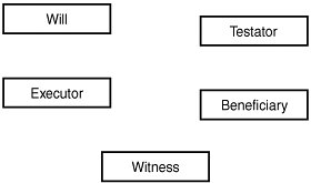
The current universe of entities is shown in Figure 5.15.
Figure 5.15. An initial diagram showing entities for will, testator, executor, beneficiary, witness.
With this entity list in place, you need to fill in the attributes. Some of these may arise from the process description, whereas you may need to fill in others based on common sense or further investigation. Take a look at the entities one by one.
For the will, you know that the date is one important attribute. Witnesses and beneficiaries are important too, but you've decided that these are entities in their own right. So for now leave the Will entity with just a date.
The Testator is a person, so even though nothing lengthy was specified in the process description, you can reasonably assume that you'd want to capture information such as name and address. The process description states that you need to capture the death date, and you might as well ask for birth date also.
Similar logic applies to the Executor, Witness, and Beneficiary entities. All are people, so you'd presumably want their names and probably addresses as well. For witnesses, you'd also like to know the date on which they witnessed the will.
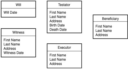
Figure 5.16 shows the developing diagram with these attributes added.
Figure 5.16. Developing ERD for a database of wills, with attributes added.
With this done, you need to consider the relationships that apply among these entities. Because Will is the critical entity, your instinct should be to look first at the way wills relate to the things around them. For each entity pair you examine, you should determine the relationship type: one-to-one, one-to-many, or many-to-many.
Consider first the relationship between a will and its witnesses. This is clearly a one-to-many relationship: A will might have only one witness, but it could certainly have several as well. The same is true of the relationship of a will to its beneficiaries. What about the relationship of a will to an executor? Well, there is generally only one executor, but in extraordinary cases there might be more than one. Again you have a one-to-many relationship.
And finally, what about the relationship between a will and a testator? Well, a will can apply to only one testator, so you might first be tempted to call this a one-to-one relationship. But one person (testator) could in theory have several wills, one superseding the other over time. To retain that flexibility, you might be better off thinking of this as a one-to-many relationship (one testator, many wills).
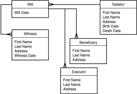
What about other relationships? Is it meaningful to talk about a relationship between witnesses and beneficiaries, for example? Probably not. In any case, you now have an ERD that connects all the entities together: Each entity is now related to every other entity through the main entity, which is Will. The resulting ERD is shown in Figure 5.17.
Figure 5.17. The wills ERD with all relationships drawn.
The last step in the process, though not a mandatory one, is to add the optionalities to the existing relationships. There won't be too many surprises with this system. The couplings here are generally loose. It might well be permissible to have a testator with no wills in the system, for example. It's not likely that a will would have no beneficiaries, but it is possible. And a will need not have associated witnesses, at least not until it's signed. A will might even sit in limbo for a while with no executor assigned. So these relationships are all fairly loose. The ERD with optionalities might appear as in Figure 5.18.
Figure 5.18. The wills ERD with optionalities added.
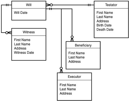
We've made a slight simplification here, for the purpose of clarity. The diagram indicates that one witness can only ever witness one will. In truth, one person could witness quite a number of wills, which would entail a many-to-many relationship between witnesses and wills. Here, we're effectively presuming that we'll make a new Witness record every time someone witnesses a will, whether or not that person has already done so.
Adding Attributes
Now you have a pretty good list of entities, but they still need attributes. (These, again, are likely to turn into database fields when you actually build the system.)
Add the Primary Keys
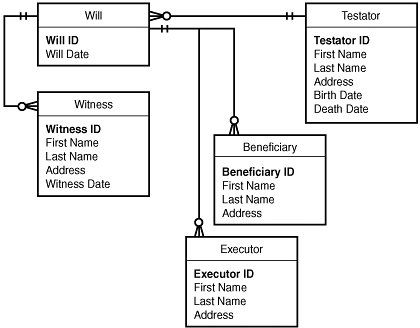
You might remember that earlier it was recommended that every entity, without exception, have a primary key. So the first thing to do is add a primary key to each entity in the diagram. Figure 5.19 shows the result.
Figure 5.19. The wills ERD with primary keys added.
Add the Foreign Keys
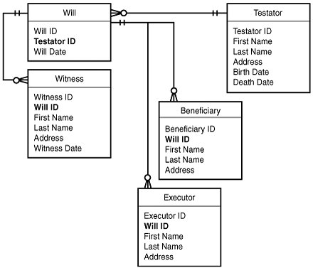
Foreign keys, you'll remember, tie the rows of one table to the primary key of another table. Anywhere you have a one-to-many relationship indicated on your ERD, you need two things: a primary key on the "one" side, and a foreign key on the "many" side. In the current example, beneficiaries and witnesses both have a many-to-one relationship with wills. So, in addition to their own primary keys (Beneficiary ID and Witness ID, which you've already added), they each need to store a foreign key called Will ID that ties each beneficiary or witness record back to a unique record in the Will table. Figure 5.20 shows the ERD with foreign keys added.
Figure 5.20. The wills ERD with foreign keys added.
Add the "Other" Attributes
The keys you've just added represent the ERD's structural attributes. These are the minimal attributes needed to create the relationships you identified in earlier steps. What's left, of course, is all the "actual" datathe information a user of the system expects to work with.
You will have identified some of these attributes during the initial design process, and may have wrestled with the question of whether they should appear as attributes or entities (as with testator and executor in this example, both of which we're calling entities in this design). You'll find out about others as you dig deeper into the requirements for the particular system you're building. In the current example, there may be many other pieces of data about a will that these lawyers want to track. All that information would appear as additional attributes of the Will entity.
Strictly speaking, attributes don't need to appear in an ERD. An ERD, after all, is mostly about entities and relationships. In a system with complex entities, showing all the attributes on the ERD would be unwieldy and would obscure the main structure of the ERD. Just make sure that an attribute list for each entity appears somewhere in your design documents.
Tip
When you first start sketching your ERD, you might just be scribbling on the back of an envelope. But sooner or later, especially for large projects, you'll want to turn your ERD into an electronic document of some kind. We recommend that you find a suitable tool for doing this. If you want to go with a dedicated diagramming tool, Visio is popular for the PC platform, and on the Mac, OmniGraffle is an excellent tool.
But if you don't want to spring for (or worse, spend time learning) a new tool, well, FileMaker's Layout mode also makes a great ERD tool! It's easy to whip up a small set of ERD adornments and cut and paste them where needed. That way, each of your FileMaker solutions can contain its own ERD, squirreled away in a hidden layout somewhere.
Part I: Getting Started with FileMaker 8
FileMaker Overview
- FileMaker Overview
- FileMaker and Its Marketplace
- Introduction to Database Software
- FileMaker Deployment Options
- Whats New in FileMaker Pro 8
Using FileMaker Pro
- Getting Started
- Working in FileMaker Pro
- Troubleshooting
- FileMaker Extra: Becoming a FileMaker Pro Power User
Defining and Working with Fields
- Defining and Working with Fields
- Working Under the Hood
- Working with Fields
- Working with Field Types
- Assigning Field Options
- Troubleshooting
- FileMaker Extra: Indexing in FileMaker
Working with Layouts
- Working with Layouts
- Whats a Layout?
- Creating and Managing Layouts
- Working with Parts
- Working with Objects on a Layout
- Working with the Tab Control Object
- Working with Fields
- Portals
- Troubleshooting
- FileMaker Extra: Designing Cross-PlatformFriendly Layouts
Part II: Developing Solutions with FileMaker
Relational Database Design
- Relational Database Design
- Understanding Database Design
- Database Analysis
- Working with Entities and Attributes
- Understanding Relationships
- Relationship Optionality
- Understanding the Role of Keys in Database Design
- Many-to-Many Relationships: Solving the Puzzle
- The Basics of Process Analysis
- FileMaker Extra: Complex Many-to-Many Relationships
Working with Multiple Tables
- Working with Multiple Tables
- Multitable Systems in FileMaker Pro
- Creating a One-to-Many Relationship in FileMaker
- Working with Keys and Match Fields
- Understanding Table Context
- Working with Related Data
- Creating a Many-to-Many Relationship
- Relational Integrity
- Rapid Multitable Development
- Troubleshooting
- FileMaker Extra: Building a Three-Way Join
Working with Relationships
- Working with Relationships
- Relationships Graphs and ERDs
- Relationships as Queries
- Creating Self-Relationships
- Creating Ranged Relationships
- Creating Cross-Product Relationships
- Working with Data from Distant Tables
- Working with Multiple Files
- How and When to Use Multiple Files
- Troubleshooting
- FileMaker Extra: Managing the Relationships Graph
Getting Started with Calculations
- Getting Started with Calculations
- Understanding How and Where Calculations Are Used
- Exploring the Calculation Dialog Box
- Essential Functions
- Using Conditional Functions
- Aggregate Functions
- Learning About the Environment
- Troubleshooting
- FileMaker Extra: Tips for Becoming a Calculation Master
Getting Started with Scripting
- Getting Started with Scripting
- Scripts in FileMaker Pro
- Creating Scripts
- Common Scripting Topics
- Triggering Scripts
- Working with Buttons on Layouts
- Troubleshooting
- FileMaker Extra: Creating a Script Library
Getting Started with Reporting
- Getting Started with Reporting
- Deriving Meaning from Data
- Working with Lists of Data
- Summarized Reports
- Delivering Reports
- Troubleshooting
- FileMaker Extra: Incorporating Reports into the Workflow
Part III: Developer Techniques
Developing for Multiuser Deployment
- Developing for Multiuser Deployment
- Developing for Multiple Users
- Sessions in FileMaker Pro
- Concurrency
- Audit Trails in FileMaker Pro
- Launch Files
- Troubleshooting
- FileMaker Extra: Development with a Team
Implementing Security
- Approaching Security
- User-Level Internal Security
- File-Level Access Security
- Troubleshooting
- FileMaker Extra: Working with Multiple Files
Advanced Interface Techniques
- Advanced Interface Techniques
- User Interfaces in FileMaker Pro
- Navigation
- Multiwindow Interfaces
- Working with Custom Menus
- Showing/Hiding Layout Elements
- Dedicated Find Layouts
- Data Presentation
- Working with Table View
- Troubleshooting
- FileMaker Extra: User Interface Heuristics
Advanced Calculation Techniques
- Advanced Calculation Techniques
- Whats an Advanced Calculation Technique?
- Logical Functions
- Text Formatting Functions
- Array Functions
- The Filter-ing Functions
- Custom Functions
- GetNthRecord
- Troubleshooting
- FileMaker Extra: Creating a Custom Function Library
Advanced Scripting Techniques
- Advanced Scripting Techniques
- What Is Advanced Scripting?
- Script Parameters and Script Results
- Script Variables
- Window Management Techniques
- Go to Related Record
- Troubleshooting
- FileMaker Extra: Recursive Scripts
Advanced Portal Techniques
- Advanced Portal Techniques
- Portals in FileMaker Pro
- Portal Basics
- New Record Only Relationships
- Horizontal Portals
- Using Portals to Create Calendars
- Selection Portals
- Filtered Portals
- Dynamic Portal Sorting
- Troubleshooting
- FileMaker Extra: Portals and Record Locking
Debugging and Troubleshooting
- Debugging and Troubleshooting
- What Is Troubleshooting?
- Staying Out of Trouble
- Planning for Trouble
- Troubleshooting Scripts and Calculations
- Troubleshooting in Specific Areas: Performance, Context, Connectivity, and Globals
- File Maintenance and Recovery
- FileMaker Extra: Other Tools of the Trade
Converting Systems from Previous Versions of FileMaker Pro
- Converting Systems from Previous Versions of FileMaker Pro
- Migration Choices
- Converting Files
- Pre-Conversion Tasks
- Post-Conversion Tasks
- Troubleshooting
- FileMaker Extra: Converting Web-Enabled Databases
Part IV: Data Integration and Publishing
Importing Data into FileMaker Pro
- Importing Data into FileMaker Pro
- Working with External Data
- Flat-File Data Sources
- Importing Multiple Files from a Folder
- Importing Photos from a Digital Camera
- Importing from an ODBC Data Source
- Importing from an XML Data Source
- Using a Script to Import Data
- Troubleshooting
- FileMaker Extra: Exploiting the FileMaker-to-FileMaker Import
Exporting Data from FileMaker
- Exporting Data from FileMaker
- Getting Out What You Put In
- The Basic Mechanics of Exporting
- Export File Formats
- Formatting Exported Data
- Exporting Related Fields
- Exporting Grouped Data
- Exporting to Fixed-Width Formats
- Working with Large Fields and Container Fields
- Scripted Exports
- Accessing FileMaker Data Using ODBC and JDBC
- Using FileMaker Pro as an ODBC Client
- Troubleshooting
- FileMaker Extra: Accessing FileMaker Data via JDBC
Instant Web Publishing
- Instant Web Publishing
- An Overview of Instant Web Publishing
- Enabling and Configuring IWP
- Designing for IWP Deployment
- Using an IWP Solution
- Troubleshooting
- FileMaker Extra: Building Your Own Next and Previous Page Buttons
FileMaker and Web Services
- FileMaker and Web Services
- About Web Services
- FileMaker and XML
- Transforming XML
- XML Import: Understanding Web Services
- Working with Web Services
- Troubleshooting
- FileMaker Extra: Write Your Own Web Services
Custom Web Publishing
- Custom Web Publishing
- About Custom Web Publishing
- Custom Web Publishing Versus Instant Web Publishing
- Custom Web Publishing Versus XML Export
- Getting Your Databases Ready for Custom Web Publishing
- Publishing FileMaker Data as XML
- Using XSLT with Custom Web Publishing
- Building Web Applications with XSLT-CWP
- Other Custom Web Publishing Commands and Parameters
- About the FileMaker XSLT Extensions
- Troubleshooting
- FileMaker Extra: About the Custom Web Publishing Tools
Part V: Deploying a FileMaker Solution
Deploying and Extending FileMaker
- Deploying and Extending FileMaker
- FileMaker Deployment Options
- Single User
- Peer-to-Peer Hosting
- FileMaker Server
- Web Publishing
- ODBC/JDBC
- Citrix/Terminal Services
- Runtime Solutions
- Deploying to Handheld Devices
- Customized Deployment Options
- Troubleshooting
- FileMaker Extra: The Limits of Customization
FileMaker Server and Server Advanced
- FileMaker Server and Server Advanced
- About FileMaker Server
- Installing FileMaker Server
- Running FileMaker Server
- Using the Server Administration Tool
- Configuring and Administering FileMaker Server Using the SAT
- Managing Clients
- Managing Databases
- Administration from the Command Line
- Working with External Services
- Automatically Updating Plug-ins
- Scheduled Tasks
- Monitoring FileMaker Server
- Troubleshooting
- FileMaker Extra: Best Practices Checklist
FileMaker Mobile
- FileMaker Mobile
- FileMaker Mobile 8 Overview
- Using FileMaker Mobile on Your Handheld Device
- Troubleshooting
- FileMaker Extra: Publishing Related Data
Documenting Your FileMaker Solutions
- Documenting Your FileMaker Solutions
- Why Is Documentation Important?
- Developing Naming Conventions
- Using Comments Effectively
- Documenting the Relationships Graph
- Using the Database Design Report
- Using Third-Party Documentation Tools
- Putting the Finishing Touches on Your Documentation
- Final Thoughts on Documentation
- FileMaker Extra: Soliant Development Standards
EAN: 2147483647
Pages: 296
- Article 406: Receptacles, Cord Connectors, and Attachment Plugs (Caps)
- Notes to Tables
- Annex C. Conduit and Tubing Fill Tables for Conductors and Fixture Wires of the Same Size
- Example No. D4(b) Optional Calculation for Multifamily Dwelling
- Example No. D5(a) Multifamily Dwelling Served at 208Y/120 Volts, Three Phase
