(Optional) Software Engineering Case Study: Collaboration Among Objects
(Optional) Software Engineering Case Study Collaboration Among Objects
In this section, we concentrate on the collaborations (interactions) among objects. When two objects communicate with each other to accomplish a task, they are said to collaborateobjects do this by invoking one another's operations. A collaboration consists of an object of one class sending a message to an object of another class. Messages are sent in Java via method calls.
In Section 6.14, we determined many of the operations of the classes in our system. In this section, we concentrate on the messages that invoke these operations. To identify the collaborations in the system, we return to the requirements document in Section 2.9. Recall that this document specifies the range of activities that occur during an ATM session (e.g., authenticating a user, performing transactions). The steps used to describe how the system must perform each of these tasks are our first indication of the collaborations in our system. As we proceed through this and the remaining "Software Engineering Case Study" sections, we may discover additional collaborations.
Identifying the Collaborations in a System
We identify the collaborations in the system by carefully reading the sections of the requirements document that specify what the ATM should do to authenticate a user and to perform each transaction type. For each action or step described in the requirements document, we decide which objects in our system must interact to achieve the desired result. We identify one object as the sending object and another as the receiving object. We then select one of the receiving object's operations (identified in Section 6.14) that must be invoked by the sending object to produce the proper behavior. For example, the ATM displays a welcome message when idle. We know that an object of class Screen displays a message to the user via its displayMessage operation. Thus, we decide that the system can display a welcome message by employing a collaboration between the ATM and the Screen in which the ATM sends a displayMessage message to the Screen by invoking the displayMessage operation of class Screen. [Note: To avoid repeating the phrase "an object of class...," we refer to an object by using its class name preceded by an article ("a," "an" or "the")for example, "the ATM" refers to an object of class ATM.]
Figure 7.25 lists the collaborations that can be derived from the requirements document. For each sending object, we list the collaborations in the order in which they first occur during an ATM session (i.e., the order in which they are discussed in the requirements document). We list each collaboration involving a unique sender, message and recipient only once, even though the collaborations may occur at several different times throughout an ATM session. For example, the first row in Fig. 7.25 indicates that the ATM collaborates with the Screen whenever the ATM needs to display a message to the user.
|
An object of class... |
sends the message... |
to an object of class... |
|---|---|---|
|
ATM |
displayMessage |
Screen |
|
BalanceInquiry |
getAvailableBalance |
BankDatabase |
|
Withdrawal |
displayMessage |
Screen |
|
Deposit |
displayMessage |
Screen |
|
BankDatabase |
validatePIN |
Account |
Let's consider the collaborations in Fig. 7.25. Before allowing a user to perform any transactions, the ATM must prompt the user to enter an account number, then to enter a PIN. It accomplishes each of these tasks by sending a displayMessage message to the Screen. Both of these actions refer to the same collaboration between the ATM and the Screen, which is already listed in Fig. 7.25. The ATM obtains input in response to a prompt by sending a getInput message to the Keypad. Next, the ATM must determine whether the user-specified account number and PIN match those of an account in the database. It does so by sending an authenticateUser message to the BankDatabase. Recall that the BankDatabase cannot authenticate a user directlyonly the user's Account (i.e., the Account that contains the account number specified by the user) can access the user's PIN on record to authenticate the user. Figure 7.25 therefore lists a collaboration in which the BankDatabase sends a validatePIN message to an Account.
After the user is authenticated, the ATM displays the main menu by sending a series of displayMessage messages to the Screen and obtains input containing a menu selection by sending a getInput message to the Keypad. We have already accounted for these collaborations, so we do not add anything to Fig. 7.25. After the user chooses a type of transaction to perform, the ATM executes the transaction by sending an execute message to an object of the appropriate transaction class (i.e., a BalanceInquiry, a Withdrawal or a Deposit). For example, if the user chooses to perform a balance inquiry, the ATM sends an execute message to a BalanceInquiry.
Further examination of the requirements document reveals the collaborations involved in executing each transaction type. A BalanceInquiry retrieves the amount of money available in the user's account by sending a getAvailableBalance message to the BankDatabase, which responds by sending a getAvailableBalance message to the user's Account. Similarly, the BalanceInquiry retrieves the amount of money on deposit by sending a getTotalBalance message to the BankDatabase, which sends the same message to the user's Account. To display both measures of the user's balance at the same time, the BalanceInquiry sends a displayMessage message to the Screen.
A Withdrawal sends a series of displayMessage messages to the Screen to display a menu of standard withdrawal amounts (i.e., $20, $40, $60, $100, $200). The Withdrawal sends a getInput message to the Keypad to obtain the user's menu selection. Next, the Withdrawal determines whether the requested withdrawal amount is less than or equal to the user's account balance. The Withdrawal can obtain the amount of money available in the user's account by sending a getAvailableBalance message to the BankDatabase. The Withdrawal then tests whether the cash dispenser contains enough cash by sending an isSufficientCashAvailable message to the CashDispenser. A Withdrawal sends a debit message to the BankDatabase to decrease the user's account balance. The BankDatabase in turn sends the same message to the appropriate Account. Recall that debiting funds from an Account decreases both the totalBalance and the availableBalance. To dispense the requested amount of cash, the Withdrawal sends a dispenseCash message to the CashDispenser. Finally, the Withdrawal sends a displayMessage message to the Screen, instructing the user to take the cash.
A Deposit responds to an execute message first by sending a displayMessage message to the Screen to prompt the user for a deposit amount. The Deposit sends a getInput message to the Keypad to obtain the user's input. The Deposit then sends a displayMessage message to the Screen to tell the user to insert a deposit envelope. To determine whether the deposit slot received an incoming deposit envelope, the Deposit sends an isEnvelopeReceived message to the DepositSlot. The Deposit updates the user's account by sending a credit message to the BankDatabase, which subsequently sends a credit message to the user's Account. Recall that crediting funds to an Account increases the totalBalance but not the availableBalance.
Interaction Diagrams
Now that we have identified a set of possible collaborations between the objects in our ATM system, let us graphically model these interactions using the UML. The UML provides several types of interaction diagrams that model the behavior of a system by modeling how objects interact. The communication diagram emphasizes which objects participate in collaborations. [Note: Communication diagrams were called collaboration diagrams in earlier versions of the UML.] Like the communication diagram, the sequence diagram shows collaborations among objects, but it emphasizes when messages are sent between objects over time.
Communication Diagrams
Figure 7.26 shows a communication diagram that models the ATM executing a BalanceInquiry. Objects are modeled in the UML as rectangles containing names in the form objectName : ClassName. In this example, which involves only one object of each type, we disregard the object name and list only a colon followed by the class name. [Note: Specifying the name of each object in a communication diagram is recommended when modeling multiple objects of the same type.] Communicating objects are connected with solid lines, and messages are passed between objects along these lines in the direction shown by arrows. The name of the message, which appears next to the arrow, is the name of an operation (i.e., a method in Java) belonging to the receiving objectthink of the name as a "service" that the receiving object provides to sending objects (its "clients").
Figure 7.26. Communication diagram of the ATM executing a balance inquiry.
(This item is displayed on page 332 in the print version)

The solid filled arrow in Fig. 7.26 represents a messageor synchronous callin the UML and a method call in Java. This arrow indicates that the flow of control is from the sending object (the ATM) to the receiving object (a BalanceInquiry). Since this is a synchronous call, the sending object may not send another message, or do anything at all, until the receiving object processes the message and returns control to the sending object. The sender just waits. For example, in Fig. 7.26, the ATM calls method execute of a BalanceInquiry and may not send another message until execute has finished and returns control to the ATM. [Note: If this were an asynchronous call, represented by a stick arrowhead, the sending object would not have to wait for the receiving object to return controlit would continue sending additional messages immediately following the asynchronous call. Asynchronous calls are implemented in Java using a technique called multithreading, which is discussed in Chapter 23, Multithreading.]
Sequence of Messages in a Communication Diagram
Figure 7.27 shows a communication diagram that models the interactions among objects in the system when an object of class BalanceInquiry executes. We assume that the object's accountNumber attribute contains the account number of the current user. The collaborations in Fig. 7.27 begin after the ATM sends an execute message to a BalanceInquiry (i.e., the interaction modeled in Fig. 7.26). The number to the left of a message name indicates the order in which the message is passed. The sequence of messages in a communication diagram progresses in numerical order from least to greatest. In this diagram, the numbering starts with message 1 and ends with message 3. The BalanceInquiry first sends a getAvailableBalance message to the BankDatabase (message 1), then sends a getTotalBalance message to the BankDatabase (message 2). Within the parentheses following a message name, we can specify a comma-separated list of the names of the parameters sent with the message (i.e., arguments in a Java method call)the BalanceInquiry passes attribute accountNumber with its messages to the BankDatabase to indicate which Account's balance information to retrieve. Recall from Fig. 6.22 that operations getAvailableBalance and getTotalBalance of class BankDatabase each require a parameter to identify an account. The BalanceInquiry next displays the availableBalance and the totalBalance to the user by passing a displayMessage message to the Screen (message 3) that includes a parameter indicating the message to be displayed.
Figure 7.27. Communication diagram for executing a balance inquiry.
(This item is displayed on page 332 in the print version)
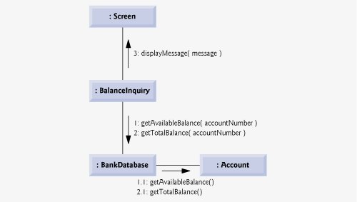
Note, however, that Fig. 7.27 models two additional messages passing from the BankDatabase to an Account (message 1.1 and message 2.1). To provide the ATM with the two balances of the user's Account (as requested by messages 1 and 2), the BankDatabase must pass a getAvailableBalance and a getTotalBalance message to the user's Account. Such messages passed within the handling of another message are called nested messages. The UML recommends using a decimal numbering scheme to indicate nested messages. For example, message 1.1 is the first message nested in message 1the BankDatabase passes a getAvailableBalance message during BankDatabase's processing of a message by the same name. [Note: If the BankDatabase needed to pass a second nested message while processing message 1, the second message would be numbered 1.2.] A message may be passed only when all the nested messages from the previous message have been passed. For example, the BalanceInquiry passes message 3 only after messages 2 and 2.1 have been passed, in that order.
The nested numbering scheme used in communication diagrams helps clarify precisely when and in what context each message is passed. For example, if we numbered the messages in Fig. 7.27 using a flat numbering scheme (i.e., 1, 2, 3, 4, 5), someone looking at the diagram might not be able to determine that BankDatabase passes the getAvailableBalance message (message 1.1) to an Account during the BankDatabase's processing of message 1, as opposed to after completing the processing of message 1. The nested decimal numbers make it clear that the second getAvailableBalance message (message 1.1) is passed to an Account within the handling of the first getAvailableBalance message (message 1) by the BankDatabase.
Sequence Diagrams
Communication diagrams emphasize the participants in collaborations, but model their timing a bit awkwardly. A sequence diagram helps model the timing of collaborations more clearly. Figure 7.28 shows a sequence diagram modeling the sequence of interactions that occur when a Withdrawal executes. The dotted line extending down from an object's rectangle is that object's lifeline, which represents the progression of time. Actions occur along an object's lifeline in chronological order from top to bottoman action near the top happens before one near the bottom.
Figure 7.28. Sequence diagram that models a Withdrawal executing.
(This item is displayed on page 334 in the print version)
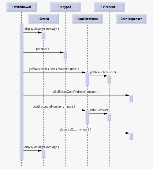
Message passing in sequence diagrams is similar to message passing in communication diagrams. A solid arrow with a filled arrowhead extending from the sending object to the receiving object represents a message between two objects. The arrowhead points to an activation on the receiving object's lifeline. An activation, shown as a thin vertical rectangle, indicates that an object is executing. When an object returns control, a return message, represented as a dashed line with a stick arrowhead, extends from the activation of the object returning control to the activation of the object that initially sent the message. To eliminate clutter, we omit the return-message arrowsthe UML allows this practice to make diagrams more readable. Like communication diagrams, sequence diagrams can indicate message parameters between the parentheses following a message name.
The sequence of messages in Fig. 7.28 begins when a Withdrawal prompts the user to choose a withdrawal amount by sending a displayMessage message to the Screen. The Withdrawal then sends a getInput message to the Keypad, which obtains input from the user. We have already modeled the control logic involved in a Withdrawal in the activity diagram of Fig. 5.31, so we do not show this logic in the sequence diagram of Fig. 7.28. Instead, we model the best-case scenario in which the balance of the user's account is greater than or equal to the chosen withdrawal amount, and the cash dispenser contains a sufficient amount of cash to satisfy the request. For information on how to model control logic in a sequence diagram, please refer to the Web resources and recommended readings listed at the end of Section 2.9.
After obtaining a withdrawal amount, the Withdrawal sends a getAvailableBalance message to the BankDatabase, which in turn sends a getAvailableBalance message to the user's Account. Assuming that the user's account has enough money available to permit the transaction, the Withdrawal next sends an isSufficientCashAvailable message to the CashDispenser. Assuming that there is enough cash available, the Withdrawal decreases the balance of the user's account (i.e., both the totalBalance and the availableBalance) by sending a debit message to the BankDatabase. The BankDatabase responds by sending a debit message to the user's Account. Finally, the Withdrawal sends a dispenseCash message to the CashDispenser and a displayMessage message to the Screen, telling the user to remove the cash from the machine.
We have identified the collaborations among objects in the ATM system and modeled some of these collaborations using UML interaction diagramsboth communication diagrams and sequence diagrams. In the next "Software Engineering Case Study" section (Section 8.19), we enhance the structure of our model to complete a preliminary object-oriented design, then we begin implementing the ATM system.
Software Engineering Case Study Self-Review Exercises
| 7.1 |
A(n) __________ consists of an object of one class sending a message to an object of another class.
|
| 7.2 |
Which form of interaction diagram emphasizes what collaborations occur?Which form emphasizes when collaborations occur? |
| 7.3 |
Create a sequence diagram that models the interactions among objects in the ATM system that occur when a Deposit executes successfully, and explain the sequence of messages modeled by the diagram. |
Answers to Software Engineering Case Study Self-Review Exercises
| 7.1 |
c. |
| 7.2 |
Communication diagrams emphasize what collaborations occur. Sequence diagrams emphasize when collaborations occur. |
| 7.3 |
Figure 7.29 presents a sequence diagram that models the interactions between objects in the ATM system that occur when a Deposit executes successfully. Figure 7.29. Sequence diagram that models a Deposit executing. (This item is displayed on page 336 in the print version) 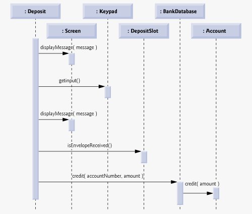
Figure 7.29 indicates that a Deposit first sends a displayMessage message to the Screen to ask the user to enter a deposit amount. Next the Deposit sends a getInput message to the Keypad to receive input from the user. The Deposit then instructs the user to enter a deposit envelope by sending a displayMessage message to the Screen. The Deposit next sends an isEnvelopeReceived message to the DepositSlot to confirm that the deposit envelope has been received by the ATM. Finally, the Deposit increases the totalBalance attribute (but not the availableBalance attribute) of the user's Account by sending a credit message to the BankDatabase. The BankDatabase responds by sending the same message to the user's Account. |
Introduction to Computers, the Internet and the World Wide Web
- Introduction
- What Is a Computer?
- Computer Organization
- Early Operating Systems
- Personal, Distributed and Client/Server Computing
- The Internet and the World Wide Web
- Machine Languages, Assembly Languages and High-Level Languages
- History of C and C++
- History of Java
- Java Class Libraries
- FORTRAN, COBOL, Pascal and Ada
- BASIC, Visual Basic, Visual C++, C# and .NET
- Typical Java Development Environment
- Notes about Java and Java How to Program, Sixth Edition
- Test-Driving a Java Application
- Software Engineering Case Study: Introduction to Object Technology and the UML (Required)
- Wrap-Up
- Web Resources
- Summary
- Terminology
- Self-Review Exercises
- Exercises
Introduction to Java Applications
- Introduction
- First Program in Java: Printing a Line of Text
- Modifying Our First Java Program
- Displaying Text with printf
- Another Java Application: Adding Integers
- Memory Concepts
- Arithmetic
- Decision Making: Equality and Relational Operators
- (Optional) Software Engineering Case Study: Examining the Requirements Document
- Wrap-Up
- Summary
- Terminology
- Self-Review Exercises
- Exercises
Introduction to Classes and Objects
- Introduction
- Classes, Objects, Methods and Instance Variables
- Declaring a Class with a Method and Instantiating an Object of a Class
- Declaring a Method with a Parameter
- Instance Variables, set Methods and get Methods
- Primitive Types vs. Reference Types
- Initializing Objects with Constructors
- Floating-Point Numbers and Type double
- (Optional) GUI and Graphics Case Study: Using Dialog Boxes
- (Optional) Software Engineering Case Study: Identifying the Classes in a Requirements Document
- Wrap-Up
- Summary
- Terminology
- Self-Review Exercises
- Exercises
Control Statements: Part I
- Introduction
- Algorithms
- Pseudocode
- Control Structures
- if Single-Selection Statement
- if...else Double-Selection Statement
- while Repetition Statement
- Formulating Algorithms: Counter-Controlled Repetition
- Formulating Algorithms: Sentinel-Controlled Repetition
- Formulating Algorithms: Nested Control Statements
- Compound Assignment Operators
- Increment and Decrement Operators
- Primitive Types
- (Optional) GUI and Graphics Case Study: Creating Simple Drawings
- (Optional) Software Engineering Case Study: Identifying Class Attributes
- Wrap-Up
- Summary
- Terminology
- Self-Review Exercises
- Exercises
Control Statements: Part 2
- Introduction
- Essentials of Counter-Controlled Repetition
- for Repetition Statement
- Examples Using the for Statement
- do...while Repetition Statement
- switch Multiple-Selection Statement
- break and continue Statements
- Logical Operators
- Structured Programming Summary
- (Optional) GUI and Graphics Case Study: Drawing Rectangles and Ovals
- (Optional) Software Engineering Case Study: Identifying Objects States and Activities
- Wrap-Up
- Summary
- Terminology
- Self-Review Exercises
- Exercises
Methods: A Deeper Look
- Introduction
- Program Modules in Java
- static Methods, static Fields and Class Math
- Declaring Methods with Multiple Parameters
- Notes on Declaring and Using Methods
- Method Call Stack and Activation Records
- Argument Promotion and Casting
- Java API Packages
- Case Study: Random-Number Generation
- Case Study: A Game of Chance (Introducing Enumerations)
- Scope of Declarations
- Method Overloading
- (Optional) GUI and Graphics Case Study: Colors and Filled Shapes
- (Optional) Software Engineering Case Study: Identifying Class Operations
- Wrap-Up
- Summary
- Terminology
- Self-Review Exercises
- Exercises
Arrays
- Introduction
- Arrays
- Declaring and Creating Arrays
- Examples Using Arrays
- Case Study: Card Shuffling and Dealing Simulation
- Enhanced for Statement
- Passing Arrays to Methods
- Case Study: Class GradeBook Using an Array to Store Grades
- Multidimensional Arrays
- Case Study: Class GradeBook Using a Two-Dimensional Array
- Variable-Length Argument Lists
- Using Command-Line Arguments
- (Optional) GUI and Graphics Case Study: Drawing Arcs
- (Optional) Software Engineering Case Study: Collaboration Among Objects
- Wrap-Up
- Summary
- Terminology
- Self-Review Exercises
- Exercises
- Special Section: Building Your Own Computer
Classes and Objects: A Deeper Look
- Introduction
- Time Class Case Study
- Controlling Access to Members
- Referring to the Current Objects Members with the this Reference
- Time Class Case Study: Overloaded Constructors
- Default and No-Argument Constructors
- Notes on Set and Get Methods
- Composition
- Enumerations
- Garbage Collection and Method finalize
- static Class Members
- static Import
- final Instance Variables
- Software Reusability
- Data Abstraction and Encapsulation
- Time Class Case Study: Creating Packages
- Package Access
- (Optional) GUI and Graphics Case Study: Using Objects with Graphics
- (Optional) Software Engineering Case Study: Starting to Program the Classes of the ATM System
- Wrap-Up
- Summary
- Terminology
- Self-Review Exercises
- Exercises
Object-Oriented Programming: Inheritance
- Introduction
- Superclasses and Subclasses
- protected Members
- Relationship between Superclasses and Subclasses
- Constructors in Subclasses
- Software Engineering with Inheritance
- Object Class
- (Optional) GUI and Graphics Case Study: Displaying Text and Images Using Labels
- Wrap-Up
- Summary
- Terminology
- Self-Review Exercises
- Exercises
Object-Oriented Programming: Polymorphism
- Introduction
- Polymorphism Examples
- Demonstrating Polymorphic Behavior
- Abstract Classes and Methods
- Case Study: Payroll System Using Polymorphism
- final Methods and Classes
- Case Study: Creating and Using Interfaces
- (Optional) GUI and Graphics Case Study: Drawing with Polymorphism
- (Optional) Software Engineering Case Study: Incorporating Inheritance into the ATM System
- Wrap-Up
- Summary
- Terminology
- Self-Review Exercises
- Exercises
GUI Components: Part 1
- Introduction
- Simple GUI-Based Input/Output with JOptionPane
- Overview of Swing Components
- Displaying Text and Images in a Window
- Text Fields and an Introduction to Event Handling with Nested Classes
- Common GUI Event Types and Listener Interfaces
- How Event Handling Works
- JButton
- Buttons that Maintain State
- JComboBox and Using an Anonymous Inner Class for Event Handling
- JList
- Multiple-Selection Lists
- Mouse Event Handling
- Adapter Classes
- JPanel Subclass for Drawing with the Mouse
- Key-Event Handling
- Layout Managers
- Using Panels to Manage More Complex Layouts
- JTextArea
- Wrap-Up
- Summary
- Terminology
- Self-Review Exercises
- Exercises
Graphics and Java 2D™
- Introduction
- Graphics Contexts and Graphics Objects
- Color Control
- Font Control
- Drawing Lines, Rectangles and Ovals
- Drawing Arcs
- Drawing Polygons and Polylines
- Java 2D API
- Wrap-Up
- Summary
- Terminology
- Self-Review Exercises
- Exercises
Exception Handling
- Introduction
- Exception-Handling Overview
- Example: Divide By Zero Without Exception Handling
- Example: Handling ArithmeticExceptions and InputMismatchExceptions
- When to Use Exception Handling
- Java Exception Hierarchy
- finally block
- Stack Unwinding
- printStackTrace, getStackTrace and getMessage
- Chained Exceptions
- Declaring New Exception Types
- Preconditions and Postconditions
- Assertions
- Wrap-Up
- Summary
- Terminology
- Self-Review Exercises
- Exercises
Files and Streams
- Introduction
- Data Hierarchy
- Files and Streams
- Class File
- Sequential-Access Text Files
- Object Serialization
- Random-Access Files
- Additional java.io Classes
- Opening Files with JFileChooser
- Wrap-Up
- Summary
- Terminology
- Self-Review Exercises
- Exercises
Recursion
- Introduction
- Recursion Concepts
- Example Using Recursion: Factorials
- Example Using Recursion: Fibonacci Series
- Recursion and the Method Call Stack
- Recursion vs. Iteration
- String Permutations
- Towers of Hanoi
- Fractals
- Recursive Backtracking
- Wrap-Up
- Internet and Web Resources
- Summary
- Terminology
- Self-Review Exercises
- Exercises
Searching and Sorting
- Introduction
- Searching Algorithms
- Sorting Algorithms
- Invariants
- Wrap-up
- Summary
- Terminology
- Self-Review Exercises
- Exercises
Data Structures
- Introduction
- Type-Wrapper Classes for Primitive Types
- Autoboxing and Auto-Unboxing
- Self-Referential Classes
- Dynamic Memory Allocation
- Linked Lists
- Stacks
- Queues
- Trees
- Wrap-Up
- Summary
- Terminology
- Self-Review Exercises
- Exercises
- Special Section: Building Your Own Compiler
Generics
- Introduction
- Motivation for Generic Methods
- Generic Methods: Implementation and Compile-Time Translation
- Additional Compile-Time Translation Issues: Methods That Use a Type Parameter as the Return Type
- Overloading Generic Methods
- Generic Classes
- Raw Types
- Wildcards in Methods That Accept Type Parameters
- Generics and Inheritance: Notes
- Wrap-Up
- Internet and Web Resources
- Summary
- Terminology
- Self-Review Exercises
- Exercises
Collections
- Introduction
- Collections Overview
- Class Arrays
- Interface Collection and Class Collections
- Lists
- Collections Algorithms
- Stack Class of Package java.util
- Class PriorityQueue and Interface Queue
- Sets
- Maps
- Properties Class
- Synchronized Collections
- Unmodifiable Collections
- Abstract Implementations
- Wrap-Up
- Summary
- Terminology
- Self-Review Exercises
- Exercises
Introduction to Java Applets
- Introduction
- Sample Applets Provided with the JDK
- Simple Java Applet: Drawing a String
- Applet Life-Cycle Methods
- Initializing an Instance Variable with Method init
- Sandbox Security Model
- Internet and Web Resources
- Wrap-Up
- Summary
- Terminology
- Self-Review Exercises
- Exercises
Multimedia: Applets and Applications
- Introduction
- Loading, Displaying and Scaling Images
- Animating a Series of Images
- Image Maps
- Loading and Playing Audio Clips
- Playing Video and Other Media with Java Media Framework
- Wrap-Up
- Internet and Web Resources
- Summary
- Terminology
- Self-Review Exercises
- Exercises
- Special Section: Challenging Multimedia Projects
GUI Components: Part 2
- Introduction
- JSlider
- Windows: Additional Notes
- Using Menus with Frames
- JPopupMenu
- Pluggable Look-and-Feel
- JDesktopPane and JInternalFrame
- JTabbedPane
- Layout Managers: BoxLayout and GridBagLayout
- Wrap-Up
- Summary
- Terminology
- Self-Review Exercises
- Exercises
Multithreading
- Introduction
- Thread States: Life Cycle of a Thread
- Thread Priorities and Thread Scheduling
- Creating and Executing Threads
- Thread Synchronization
- Producer/Consumer Relationship without Synchronization
- Producer/Consumer Relationship with Synchronization
- Producer/Consumer Relationship: Circular Buffer
- Producer/Consumer Relationship: ArrayBlockingQueue
- Multithreading with GUI
- Other Classes and Interfaces in java.util.concurrent
- Monitors and Monitor Locks
- Wrap-Up
- Summary
- Terminology
- Self-Review Exercises
- Exercises
Networking
- Introduction
- Manipulating URLs
- Reading a File on a Web Server
- Establishing a Simple Server Using Stream Sockets
- Establishing a Simple Client Using Stream Sockets
- Client/Server Interaction with Stream Socket Connections
- Connectionless Client/Server Interaction with Datagrams
- Client/Server Tic-Tac-Toe Using a Multithreaded Server
- Security and the Network
- Case Study: DeitelMessenger Server and Client
- Wrap-Up
- Summary
- Terminology
- Self-Review Exercises
- Exercises
Accessing Databases with JDBC
- Introduction
- Relational Databases
- Relational Database Overview: The books Database
- SQL
- Instructions to install MySQL and MySQL Connector/J
- Instructions on Setting MySQL User Account
- Creating Database books in MySQL
- Manipulating Databases with JDBC
- Stored Procedures
- RowSet Interface
- Wrap-Up
- Internet and Web Resources
- Recommended Readings
- Summary
- Terminology
- Self-Review Exercises
- Exercises
Servlets
- Introduction
- Servlet Overview and Architecture
- Setting Up the Apache Tomcat Server
- Handling HTTP get Requests
- Handling HTTP get Requests Containing Data
- Handling HTTP post Requests
- Redirecting Requests to Other Resources
- Multitier Applications: Using JDBC from a Servlet
- Welcome Files
- Wrap-Up
- Internet and Web Resources
- Summary
- Terminology
- Self-Review Exercises
- Exercises
JavaServer Pages (JSP)
- Introduction
- JavaServer Pages Overview
- First JSP Example
- Implicit Objects
- Scripting
- Standard Actions
- Directives
- Case Study: Guest Book
- Wrap-Up
- Internet and Web Resources
- Summary
- Terminology
- Self-Review Exercises
- Exercises
Formatted Output
- Introduction
- Streams
- Formatting Output with printf
- Printing Integers
- Printing Floating-Point Numbers
- Printing Strings and Characters
- Printing Dates and Times
- Other Conversion Characters
- Printing with Field Widths and Precisions
- Using Flags in the printf Format String
- Printing with Argument Indices
- Printing Literals and Escape Sequences
- Formatting Output with Class Formatter
- Wrap-Up
- Summary
- Terminology
- Self-Review Exercises
- Exercises
Strings, Characters and Regular Expressions
- Introduction
- Fundamentals of Characters and Strings
- Class String
- Class StringBuffer
- Class Character
- Class StringTokenizer
- Regular Expressions, Class Pattern and Class Matcher
- Wrap-Up
- Summary
- Terminology
- Self-Review Exercises
- Exercises
- Special Section: Advanced String-Manipulation Exercises
- Special Section: Challenging String-Manipulation Projects
Appendix A. Operator Precedence Chart
Appendix B. ASCII Character Set
Appendix C. Keywords and Reserved Words
Appendix D. Primitive Types
Appendix E. (On CD) Number Systems
Appendix F. (On CD) Unicode®
Appendix G. Using the Java API Documentation
Appendix H. (On CD) Creating Documentation with javadoc
Appendix I. (On CD) Bit Manipulation
Appendix J. (On CD) ATM Case Study Code
Appendix K. (On CD) Labeled break and continue Statements
Appendix L. (On CD) UML 2: Additional Diagram Types
Appendix M. (On CD) Design Patterns
Appendix N. Using the Debugger
Inside Back Cover
EAN: 2147483647
Pages: 615
