Hack 59. Scan for Wireless Networks Automatically


Build yourself a motorized scanner that shows you all wireless networks in 360 degrees.
If you've done any number of wireless surveys, you know that one of the most time-consuming parts of the survey is moving the antenna. This is especially true if you are working with highly directional antennas. Sometimes, you might not have another person with you to move the antenna and take signal measurements.
The Automatic WLAN Scanner (AWS) is designed to help with these problems. It will perform a 360-degree scan for wireless networks and then give you the SSID, signal strength, noise, and best antenna position for all discovered networks.
4.9.1. Requirements
An AWS can be built inexpensively. For my prototype system, I used a number of components, many of which were scavenged from old computers or from second-hand electronics stores. You will need:
- Hard disk frame from an ATX case
- AC/DC wall-wart power supply
- Standard ATX power connectors
- Flat-bed scanner
- Reverse-SMA microwave connector
- Screws
- Hot glue gun
- Stepping motor
- Cantenna [Hack #86]
- Orinoco 802.11b wireless card
- Antenna cable & pigtail
- SMC800 Stepping motor steering card
- Ball bearings
- Worm drive
- Cog-wheel or toothed wheel
4.9.2. Construction
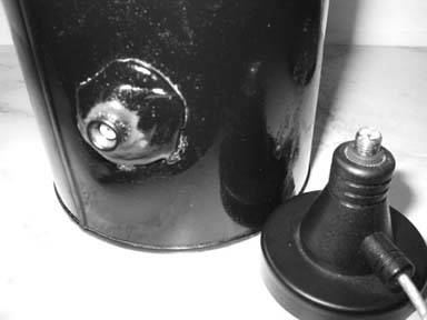
You could build the cantenna by following the instructions in "Pirouette Can Waveguide" [Hack #86]. However, I've made a modification to the design, as shown in Figure 4-13. I disassembled an omni antenna with a magnetic base. At the top of the magnetic base is a female Reverse SMA [Appendix A]) connector. Therefore, I constructed the cantenna with a male Reverse SMA connector, so that the cantenna easily screws onto the magnetic base.
Figure 4-13. Cantenna with magnetic base
Once you have completed the cantenna, the next step is to build the base, which will house the motor, worm gear, cog-wheel, and ball bearings to drive the cantenna. Figure 4-14 shows an overview of the assembled base, turned upside down. I used a hard drive frame from an ATX computer case, but you could cut your own sheet metal as well.
Figure 4-14. Upside-down view of the base
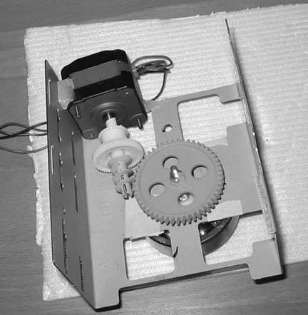
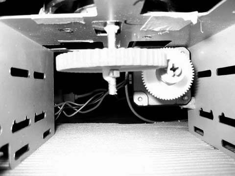
As you can see, placement of the motor is critical. You will want to first get the cog-wheel installed using a long bolt and nuts, and connect the bolt to the ball bearing on the other side of the base, as shown in Figure 4-15.
Now that the cog-wheel and ball bearing are in place, attach the worm drive to the motor shaft and experiment with the best placement for the motor. When you find the best place, make sure to mark it clearly on the base so you don't lose the location. Next, use the hot glue gun to hold the motor in place on the metal hard disk frame.
Figure 4-15. Close-up view of cog-wheel mounting
With the base constructed, you can now turn it over, as shown in Figure 4-16. The ball bearing will rotate under command of the stepper motor and worm drive, and the magnetic base of the antenna will hold the can firmly in place while the motor turns.
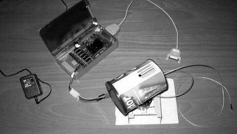
I chose to house the SMC800 card in a small metal tin, which gives the card protection when the lid is closed. One end of the tin is cut out to allow connection of the parallel cable to the SMC800. In the other end of the tin, I punched a small hole for the power cables. The three power cables from one side of the ATX power cable were ran through the tin and connected to the SMC800 card pins that drive the external motor, and the other side of the connector was wired directly to the motor.
Power is supplied to the SMC800 card using an external AC/DC adapter. Prior to the installation of the card in the red tin, I made a third hole to allow insertion of the power adapter to the card. Figure 4-17 shows the power and data connections to the card.
Figure 4-16. The base ready for antenna mounting
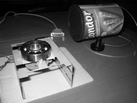
Figure 4-17. Power and data connections
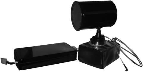
The hardware construction of the AWS is complete at this point. For my finished unit, shown in Figure 4-18, I spray-painted the tin and the cantenna and enclosed the base in waterproof vinyl. Lastly, I sealed the area between the ball bearing and the vinyl with hot glue.
Figure 4-18. The finished AWS hardware
4.9.3. Software
The SMC800 is an old card that has only DOS drivers available. Since my project relies on NetStumbler [Hack #24] to discover the wireless networks, I had to write new Windows XP drivers for the SMC800. These drivers, along with the other software I wrote for the project, are all available on my web site at http://aws.netzfund.de.
The second necessary piece of software is a Visual Basic script, which runs under NetStumbler and reads out the necessary wireless data.
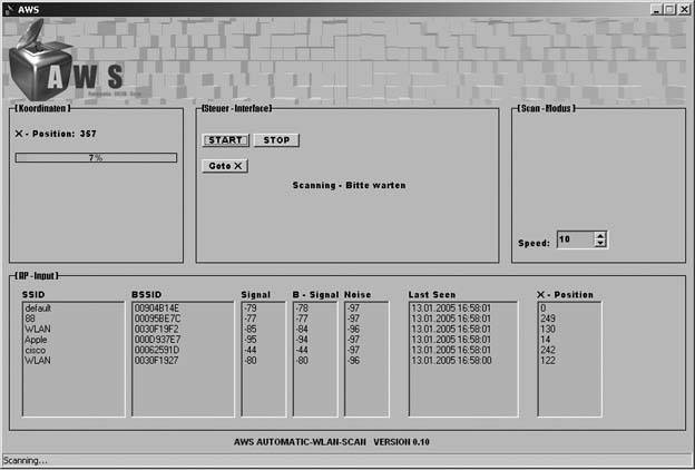
The third piece is the AWS control software, which uses the new driver for the SMC800 to control the card over the parallel interface. Using the software, you can set your own scan speed, depending on your requirements. You can also start and stop the scan, and then go to a specific stepping position on the motor.
The AWS software receives input from the Visual Basic script running with NetStumbler, and shows the data as it is received. Figure 4-19 shows the AWS software up and running.
Figure 4-19. The AWS software in action
4.9.4. Hacking the Hack
The next feature that I plan for AWS is a position-locating system, so that AWS will steer the antenna in real time to follow a moving wireless source. Obviously, one limitation of the AWS as built is that it is capable of scanning only on a single flat plane. In order to scan above or below the horizon, you will need a variable mount for the cantenna.
Marcel Bilal
Bluetooth, Mobile Phones, and GPS
- Hacks 122: Introduction
- Hack 1. Set Up Bluetooth on Linux
- Hack 2. Set Up Bluetooth on Windows XP
- Hack 3. Connect Mac OS X with a Bluetooth Phone
- Hack 4. Connect Linux with a Bluetooth Phone
- Hack 5. Connect Windows XP with a Bluetooth Phone
- Hack 6. Use Your Treo as a Modem
- Hack 7. Send SMS from a PowerBook
- Hack 8. Remote Control Mac OS X with Bluetooth Phones and PDAs
- Hack 9. Remote Control Linux with a Bluetooth Phone
- Hack 10. Control XMMS with Bluetooth
- Hack 11. Liven Up Parties with a Participatory Slideshow
- Hack 12. Send SMS from Linux
- Hack 13. Remote Control Windows with Bluetooth Phones and PDAs
- Hack 14. Control Your Bluetooth Phone with FMA
- Hack 15. Control Your Computer from Your Palm
- Hack 16. Control Your Home Theater from Your Palm
- Hack 17. Choose a Cellular Data Plan
- Hack 18. Blog from Your Mobile Phone
- Hack 19. Get Google Maps on Your Mobile Phone
- Hack 20. Share Your GPS
- Hack 21. Broadcast Your GPS Position
- Hack 22. Map Wi-Fi Networks with Kismet and GPSd
Network Discovery and Monitoring
- Hacks 2339: Introduction
- Hack 23. Find All Available Wireless Networks
- Hack 24. Discover Networks with NetStumbler
- Hack 25. Detect Networks with Handheld PCs
- Hack 26. Find and Join Wireless Networks with AP Radar
- Hack 27. Detect Networks on Mac OS X
- Hack 28. Scan Passively with KisMAC
- Hack 29. Detect Networks with Kismet
- Hack 30. Monitor Wireless Links in Linux with Wavemon
- Hack 31. Analyze Traffic with Ethereal
- Hack 32. Track 802.11 Frames in Ethereal
- Hack 33. Watch Network Traffic
- Hack 34. grep Your Network
- Hack 35. Check Wi-Fi Network Performance with Qcheck
- Hack 36. Estimate Network Performance
- Hack 37. Get Real-Time Network Stats
- Hack 38. Graph Your Wireless Performance
- Hack 39. Find Radio Manufacturers by MAC
Wireless Security
- Hacks 4051: Introduction
- Hack 40. Stop Moochers from Stealing Your Wi-Fi Bandwidth
- Hack 41. Visualize a Network
- Hack 42. Secure Your Linux Network with WPA
- Hack 43. Control Wireless Access by MAC
- Hack 44. Authenticate Wireless Users
- Hack 45. Forward Ports over SSH
- Hack 46. Proxy Web Traffic over SSH
- Hack 47. Securely Connect Two Networks
- Hack 48. Generate a Tunnel Configuration Automatically
- Hack 49. Poll Wireless Clients
- Hack 50. Interrogate the Network
- Hack 51. Track Wireless Users
Hardware Hacks
- Hacks 5262: Introduction
- Hack 52. Add an External Antenna
- Hack 53. Do-It-Yourself Access Point Hardware
- Hack 54. Boot from a Compact Flash Hard Drive
- Hack 55. Increase the Range of a PowerBook
- Hack 56. Send Power over Your Ethernet
- Hack 57. The NoCat Night Light
- Hack 58. Upgrade the Linksys WET11
- Hack 59. Scan for Wireless Networks Automatically
- Hack 60. Backlight Your Zipit
- Hack 61. Unwire Your Pistol Mouse
- Hack 62. Mobilize Your WRT54G with the WiFiCar
Software Hacks
- Hacks 6382: Introduction
- Hack 63. Build Your Own Access Point with Linux
- Hack 64. Bridge Your Linux AP
- Hack 65. Protect Your Bridge with a Firewall
- Hack 66. Filter MAC with HostAP and Madwifi
- Hack 67. Upgrade Your Wireless Router
- Hack 68. Set Up an OLSR Mesh Network
- Hack 69. Extend Your Wireless Network with WDS
- Hack 70. Pebble
- Hack 71. Wall Off Your Wireless
- Hack 72. Run Your Mac as an Access Point
- Hack 73. Run Linux on the Zipit Wireless Messenger
- Hack 74. Capture Wireless Users with NoCatAuth
- Hack 75. Capture Wireless Users on a Small Scale
- Hack 76. Build an Online Community in Your Offline Neighborhood
- Hack 77. Manage Multiple AirPort Base Stations
- Hack 78. Advertise Bonjour Services in Linux
- Hack 79. Advertise Any Service with Bonjour in Mac OS X
- Hack 80. Redirect Brought to you by Bonjour Ads
- Hack 81. Use a Windows-Only Wireless Card in Linux
- Hack 82. Use Your Orinoco Card with Hermes AP
Do-It-Yourself Antennas
- Hacks 8393: Introduction
- Hack 83. Make a Deep Dish Cylindrical Parabolic Reflector
- Hack 84. Spider Omni Antenna
- Hack 85. Pringles Can Waveguide
- Hack 86. Pirouette Can Waveguide
- Hack 87. Primestar Dish with Waveguide Feed
- Hack 88. Primestar Dish with Biquad Feed
- Hack 89. Cut a Cable Omni Antenna
- Hack 90. Build a Slotted Waveguide Antenna
- Hack 91. The Passive Repeater
- Hack 92. Determine Your Antenna Gain
- Hack 93. Build Cheap, Effective Roof Mounts
Wireless Network Design
- Hacks 94100: Introduction
- Hack 94. Analyze Elevation Profiles for Better Long-Range Wireless Networking
- Hack 95. Build a Wireless Network for the Large House
- Hack 96. Establish Line of Sight
- Hack 97. Calculate the Link Budget
- Hack 98. Align Antennas at Long Distances
- Hack 99. Slow Down to Speed Up
- Hack 100. Take Advantage of Antenna Polarization
Appendix A. Wireless Standards
- Appendix A. Wireless Standards
- Section A.1. 802.11: The Mother of All IEEE Wireless Ethernet
- Section A.2. 802.11a: The Betamax of the 802.11 Family
- Section A.3. 802.11b: The De Facto Standard
- Section A.4. 802.11g: Like 802.11b, only Faster
- Section A.5. 802.16: WiMAX Long Distance Wireless Infrastructure
- Section A.6. Bluetooth: Cable Replacement for Devices
- Section A.7. 900 MHz: Low Speed, Better Coverage
- Section A.8. CDPD, 1xRTT, and GPRS: Cellular Data Networks
- Section A.9. FRS and GMRS: Super Walkie-Talkies
- Section A.10. 802.1x: Port Security for Network Communications
- Section A.11. WPA & 802.11i
- Section A.12. BSS Versus IBSS
Appendix B. Wireless Hardware Guide
EAN: 2147483647
Pages: 178
