Hack 89. Cut a Cable Omni Antenna


Make a high-gain omni out of bits of feed cable.
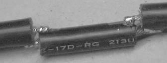
Most of the designs on the Web for a 2.4 GHz omni antenna seem to involve brass tubing and LMR-400 cable, none of which are readily available to me. I then found a coax-only design for 444 MHz that was based on the same designs. The only reasonable cable I could get my hands on was RG-213 from Maplin (http://www.maplin.co.uk). I thought I'd give it a try by scaling the 444 MHz design up to 2.4 GHz and using RG-213. In order to get about a 6 dB gain from the antenna, it needs 8 sectors, with a 1/4 wave section at the top and a fly lead with an N-connector at the bottom.
It should take about two to three hours to build an antenna using this design, but don't worry if it takes longer. You will get quicker, especially as you need to make the jig only once. Figure 6-12 shows the completed antenna.
Figure 6-12. The completed omni antenna

Each sector of the antenna needs to be 1/2 a wavelength long, multiplied by the velocity factor of the cable. The velocity factor of RG-213 is 0.66. If you decide to use a different cable (such as LMR-400), you need to get the velocity factor of that cable (which will be different), and recalculate all the dimensions:
				 V * C 0.66 * 299792458
		1/2 wavelength = ------ = ---------------- = 0.0405m = 40.5mm
				 2 * F 2 * 2441000000

		V = Velocity Factor of RG213 = 0.66
		C = Speed of light = 299792458
		F = Frequency of Signal = 2441000000 (mid point of 2.4Ghz range)
The 1/4 wave element is not adjusted by the velocity factor, as it is in the open, so it works out at just 31 mm long, giving a total antenna length of 355 mm + fly lead.
All of the parts needed to make this antenna are available cheaply from either Maplin or any DIY shop. You need the following:
1 meter RG-213U cable
Available by the meter from Maplin. One meter is enough for two antennas. Buy more for whatever fly-lead length you want.
1 N connector
Depending on what you want to connect the antenna to, use either male or female connectors, and inline or bulkhead. Remember that inline connectors need to fit 10 mm diameter RG-213 cable.
20 mm PVC conduit
Available from any DIY store, the conduit should have a 20 mm inside diameter, and 22 mm outside.
22 mm pipe clips
Depending on how you want to mount the antenna, pipe clips make mounting the antenna easy.
You also need the following standard tools:
- Millimeter ruler for measuring
- Junior hacksaw
- Stanley blade knife
- Pliers
- Standard soldering iron (you don't need a heavy duty one) and solder
- Scraps of wood to make a jig to aid soldering
- Bench or vise to hold the cable while you cut it
6.8.1. Cutting the Pieces
After much trial and error, I found that the neatest way to cut the cable is actually with a junior hacksaw. It gives a much cleaner finish than wire cutters. Each sector consists of a short length of RG-213 cable, with the central core sticking out each end.
When building the antenna, the exact length of each piece of RG-213 is not that important; it is the overall length of each sector that counts. I found that cutting the cable to 37 mm with 6 mm of core sticking out each end gets enough overlap to easily solder the segments together. If you allow 1 mm for the width of the hacksaw when cutting the sectors apart, it means you need 37 + 6 + 6 + 1 = 50 mm of cable for each sector. Making 8 sectors + 1/4 wave section comes to 420 mm of cable for the antenna + cable for the fly lead.
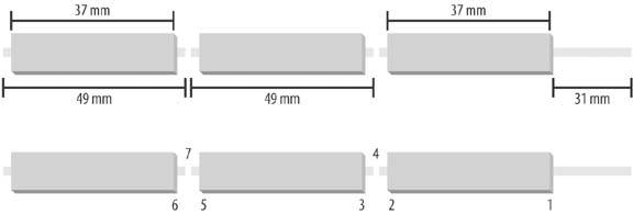
The best way to cut each sector is to make the cuts where each end of the sheathed section of the sector will be, before making the cut between each sector. Figure 6-13 displays the top three sections of the antenna, and the 1/4 wave section, showing the order that the cuts should be made.
Figure 6-13. Segment lengths
The best way to make the cuts is to mark them out on the cable first. When sawing the cable, you'll find it has a tendency to deform and bend, so lightly sawing round the outside sheath firstbut not cutting throughhelps guide the actual cut. I use the junior hacksaw to gently saw round the cable sheath to make the mark for each section.
The first mark will be at 31 mm from the end of the cable, which is for the 1/4 wave section at the top. Once you make the mark, it is time to cut around the cable. You want to cut through the sheath and shielding, and just into the central insulation, but not into the central copper wires. You might need to practice a bit first, but you should be able to feel it as you cut through the shielding into the central insulation. By leaving plenty of sheathed section on either side of the cuts, the shielding stays in place when being cut.
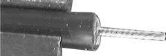
Now with pliers, gently twist off 31 mm of sheath and shielding at the end of the cable. This should leave the central insulator exposed. Using the Stanley knife, score round through the central insulator (not too hard, or you will cut the central cable). Now twist off the insulation, as shown in Figure 6-14. You should be able to see the twist in the central cable through the insulation, which will show you which way to twist off the insulation, resulting in the central core twisting more tightly.
Figure 6-14. Exposing the center conductor
The next mark is 37 mm down (68 mm from end of the cable) and is the cut for the other end of the sheathed section of the top sector. The next mark is 13 mm down (this section consists of 6 mm core from each sector and 1 mm for the cut between sectors; 81 mm from the end) and is the top of the sheathed section of the second sector. The next mark is again 37 mm down, then 13 mm, then 37 mm, and so on, until you have each of the sheathed sections marked out.
You can now start making the cuts, remembering to cut only through the sheath and shielding, and just into the central insulation. First make the cut at 37 mm down, then make the next cut another 13 mm down. You might find that some of the shielding pulls out when you make this cut, as the 13 mm length of sheath cannot hold the shielding tight enough. Don't worry; it doesn't matter.
Now you are ready to cut off the top sector from the cable. Cut through the whole cable at the midpoint of the two cuts you just made; that is, about 43.5 mm from the end of the sheath, or 74.5 mm from the end of the cable (see position 4 in Figure 6-13). Just carefully saw the whole way through the cable. Now, you can pull off the sheath and shielding from each end.
Score around the insulation as you did before, being careful not to cut the central cable. Carry on, making cuts 37 mm down from the end of the sheath, and then 13 mm further down (50 mm from the end of the sheath). Then, cut through the cable in the middle of the two cuts. Another sector made. You need 8 sectors total. Make the same cuts as usual for the eighth sector, as it will make the top of the fly lead as well. Now that you have all 8 sectors, you need to check round the end of each sector to make sure that none of the shielding is touching the central cable, as odd strands can get left behind.
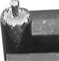
Next, you need to make a gentle V-shaped cut with the Stanley knife at each end of the sectors to expose the shielding, which is where the central core of the next sector will be soldered. Figure 6-15 shows an example V cut.
Figure 6-15. A gentle V cut
Make sure that the V cuts at each end of the sector line up; otherwise, when you come to solder the antenna together, the whole thing will be twisted all around. Once you have all eight sectors finished, it is time to put them together.
6.8.2. Building a Jig
If you do not have a handy helper to hold the sectors together, you will find it easier to make a small jig from scraps of wood to hold the sectors together as you solder them. The clamps on the right side of Figure 6-16 need to be no more than 30 mm long. The baseboard of the jig must extend to the right far enough to take the whole length of the completed antenna, as the baseboard will need to support the antenna during the soldering since the antenna is not rigid enough to support itself. Don't make the clamps too tight, because you need to be able to easily lift the cable out after it has been soldered.
Figure 6-16. A jig to hold your cable while soldering
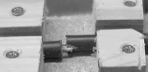
When you are ready to solder the sectors together, take care that each sector is correctly spaced. The overall length of each sector needs to be 40.5 mm. Measure from one end of the shielding of the sector that you are adding to the same end on the next sector, and slide the sectors together/apart until the distance between them is 40.5 mm. Try to get it as accurate as you can, as it affects the direction the antenna transmits in if you get it wrong. There should be a small 3 mm gap between the sheaths of each sector. Figure 6-17 shows the details of a soldered sector.
Once you have soldered each sector together, lift the sector up, turn it over, and move it down the clamp to get ready for the next sector. This results in a nice, straight antenna. When soldering, remember to heat both the shielding and core so that the solder runs smoothly and fixes them together.
Figure 6-17. A soldered section of cable
Once complete, test the cable with either a lightbulb and battery or a multimeter. The center of the fly lead should form a circuit to the 1/4 wave section, and to the shield of the fly lead to the shield of the top section. Now, test that there are no crossed connections by ensuring there is no circuit between the center of the fly lead and the shielding of the top sector, and there is no circuit between the 1/4 wave section and the shielding of the fly lead.
Fix the N connector of your choice onto the end of the fly lead. The type of connector you use depends on what you want to connect to. I use inline connectors, but you could use any connector you like. Slide the antenna into a length of conduit. It should be a snug fit, so you might need to gently ease it in. Find an old soft drink bottle top, and pop it on the top end of the antenna.
Voilà, you have one complete antenna! Securing the antenna in the conduit is best left until you are ready to mount it somewhere. You can cut 5 cm slots in the bottom of the conduit and use a jubilee clamp to grip the fly lead, drill a hole through the conduit and use a cable tie to hold the fly lead, use a bulkhead mount connector on a bottle cap and glue it to the bottom of the conduit, or glue the fly lead in place. It's up to you.
|

Bluetooth, Mobile Phones, and GPS
- Hacks 122: Introduction
- Hack 1. Set Up Bluetooth on Linux
- Hack 2. Set Up Bluetooth on Windows XP
- Hack 3. Connect Mac OS X with a Bluetooth Phone
- Hack 4. Connect Linux with a Bluetooth Phone
- Hack 5. Connect Windows XP with a Bluetooth Phone
- Hack 6. Use Your Treo as a Modem
- Hack 7. Send SMS from a PowerBook
- Hack 8. Remote Control Mac OS X with Bluetooth Phones and PDAs
- Hack 9. Remote Control Linux with a Bluetooth Phone
- Hack 10. Control XMMS with Bluetooth
- Hack 11. Liven Up Parties with a Participatory Slideshow
- Hack 12. Send SMS from Linux
- Hack 13. Remote Control Windows with Bluetooth Phones and PDAs
- Hack 14. Control Your Bluetooth Phone with FMA
- Hack 15. Control Your Computer from Your Palm
- Hack 16. Control Your Home Theater from Your Palm
- Hack 17. Choose a Cellular Data Plan
- Hack 18. Blog from Your Mobile Phone
- Hack 19. Get Google Maps on Your Mobile Phone
- Hack 20. Share Your GPS
- Hack 21. Broadcast Your GPS Position
- Hack 22. Map Wi-Fi Networks with Kismet and GPSd
Network Discovery and Monitoring
- Hacks 2339: Introduction
- Hack 23. Find All Available Wireless Networks
- Hack 24. Discover Networks with NetStumbler
- Hack 25. Detect Networks with Handheld PCs
- Hack 26. Find and Join Wireless Networks with AP Radar
- Hack 27. Detect Networks on Mac OS X
- Hack 28. Scan Passively with KisMAC
- Hack 29. Detect Networks with Kismet
- Hack 30. Monitor Wireless Links in Linux with Wavemon
- Hack 31. Analyze Traffic with Ethereal
- Hack 32. Track 802.11 Frames in Ethereal
- Hack 33. Watch Network Traffic
- Hack 34. grep Your Network
- Hack 35. Check Wi-Fi Network Performance with Qcheck
- Hack 36. Estimate Network Performance
- Hack 37. Get Real-Time Network Stats
- Hack 38. Graph Your Wireless Performance
- Hack 39. Find Radio Manufacturers by MAC
Wireless Security
- Hacks 4051: Introduction
- Hack 40. Stop Moochers from Stealing Your Wi-Fi Bandwidth
- Hack 41. Visualize a Network
- Hack 42. Secure Your Linux Network with WPA
- Hack 43. Control Wireless Access by MAC
- Hack 44. Authenticate Wireless Users
- Hack 45. Forward Ports over SSH
- Hack 46. Proxy Web Traffic over SSH
- Hack 47. Securely Connect Two Networks
- Hack 48. Generate a Tunnel Configuration Automatically
- Hack 49. Poll Wireless Clients
- Hack 50. Interrogate the Network
- Hack 51. Track Wireless Users
Hardware Hacks
- Hacks 5262: Introduction
- Hack 52. Add an External Antenna
- Hack 53. Do-It-Yourself Access Point Hardware
- Hack 54. Boot from a Compact Flash Hard Drive
- Hack 55. Increase the Range of a PowerBook
- Hack 56. Send Power over Your Ethernet
- Hack 57. The NoCat Night Light
- Hack 58. Upgrade the Linksys WET11
- Hack 59. Scan for Wireless Networks Automatically
- Hack 60. Backlight Your Zipit
- Hack 61. Unwire Your Pistol Mouse
- Hack 62. Mobilize Your WRT54G with the WiFiCar
Software Hacks
- Hacks 6382: Introduction
- Hack 63. Build Your Own Access Point with Linux
- Hack 64. Bridge Your Linux AP
- Hack 65. Protect Your Bridge with a Firewall
- Hack 66. Filter MAC with HostAP and Madwifi
- Hack 67. Upgrade Your Wireless Router
- Hack 68. Set Up an OLSR Mesh Network
- Hack 69. Extend Your Wireless Network with WDS
- Hack 70. Pebble
- Hack 71. Wall Off Your Wireless
- Hack 72. Run Your Mac as an Access Point
- Hack 73. Run Linux on the Zipit Wireless Messenger
- Hack 74. Capture Wireless Users with NoCatAuth
- Hack 75. Capture Wireless Users on a Small Scale
- Hack 76. Build an Online Community in Your Offline Neighborhood
- Hack 77. Manage Multiple AirPort Base Stations
- Hack 78. Advertise Bonjour Services in Linux
- Hack 79. Advertise Any Service with Bonjour in Mac OS X
- Hack 80. Redirect Brought to you by Bonjour Ads
- Hack 81. Use a Windows-Only Wireless Card in Linux
- Hack 82. Use Your Orinoco Card with Hermes AP
Do-It-Yourself Antennas
- Hacks 8393: Introduction
- Hack 83. Make a Deep Dish Cylindrical Parabolic Reflector
- Hack 84. Spider Omni Antenna
- Hack 85. Pringles Can Waveguide
- Hack 86. Pirouette Can Waveguide
- Hack 87. Primestar Dish with Waveguide Feed
- Hack 88. Primestar Dish with Biquad Feed
- Hack 89. Cut a Cable Omni Antenna
- Hack 90. Build a Slotted Waveguide Antenna
- Hack 91. The Passive Repeater
- Hack 92. Determine Your Antenna Gain
- Hack 93. Build Cheap, Effective Roof Mounts
Wireless Network Design
- Hacks 94100: Introduction
- Hack 94. Analyze Elevation Profiles for Better Long-Range Wireless Networking
- Hack 95. Build a Wireless Network for the Large House
- Hack 96. Establish Line of Sight
- Hack 97. Calculate the Link Budget
- Hack 98. Align Antennas at Long Distances
- Hack 99. Slow Down to Speed Up
- Hack 100. Take Advantage of Antenna Polarization
Appendix A. Wireless Standards
- Appendix A. Wireless Standards
- Section A.1. 802.11: The Mother of All IEEE Wireless Ethernet
- Section A.2. 802.11a: The Betamax of the 802.11 Family
- Section A.3. 802.11b: The De Facto Standard
- Section A.4. 802.11g: Like 802.11b, only Faster
- Section A.5. 802.16: WiMAX Long Distance Wireless Infrastructure
- Section A.6. Bluetooth: Cable Replacement for Devices
- Section A.7. 900 MHz: Low Speed, Better Coverage
- Section A.8. CDPD, 1xRTT, and GPRS: Cellular Data Networks
- Section A.9. FRS and GMRS: Super Walkie-Talkies
- Section A.10. 802.1x: Port Security for Network Communications
- Section A.11. WPA & 802.11i
- Section A.12. BSS Versus IBSS
Appendix B. Wireless Hardware Guide
EAN: 2147483647
Pages: 178
