Hack 60. Backlight Your Zipit


Add a backlight to this tiny wireless communicator, so you can use it in the dark.
The Zipit Wireless Communicator (http://www.zipitwireless.com) isan amazingly cool, cheap wireless handheld device that has just one purpose: 802.11b communications. It's marketed primarily to teens as an instant messaging device, but guess what? It also runs Linux on an ARM chip and uses an Orinoco radio card. It has a tiny 16MB of RAM and a scant 2MB of flash memory, making it difficult (but not impossible) to run applications on it. There are a number of ways to get Linux running on the Zipit [Hack #73].
There's one thing the Zipit does not include: a backlight. It's really a shame that manufacturers continue to ship devices without a backlight; it's often the kiss of death for products that otherwise might develop a following.
To add a backlight, you're going to need an electro-luminiscent (EL) panel. I found a suitable piece of EL panel for this hack at Miller Engineering (http://www.microstru.com). Secondly, you'll need a driver chip to make the EL panel work. I found a chip already mounted to a tiny board from Jelu (http://www.jelu.se/shop/product_info.php?cPath=1_29&products_id=33).
Here's a step-by-step account of how I added the backlight. No, I won't buy you a new Zipit if you break yours while attempting this.
4.10.1. Getting It Open
Flip the little guy over. Unscrew the battery cover and yank the battery. Pry up the tiny rubber feet to reveal four Phillips-head screws, as shown in Figure 4-20.
Figure 4-20. Carefully opening the Zipit
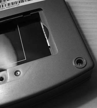
Remove them. The entire bottom should come off easily. On my unit, the sticker covering the battery area was stuck to the CPU, so you might have to gently pry that up with a screwdriver. Be careful as you pull the bottom off, because the speaker is attached to a recess in the bottom with gummy glue. Pry up the speaker and completely remove the bottom shell.
Be careful not to lose the power button cover. Take it off and put it where you put the case screws (and don't lose those either).
4.10.2. Removing the Mainboard
You'll need a soldering iron for this step. First, apply heat to the antenna connector cable and remove it from the board. Next, lift the white part of the plastic LCD panel connector (it should swing away from the board) and gently remove the brown ribbon cable.
Put the mainboard and keyboard membrane aside. You can remove the rubber keyboard too if you like.
4.10.3. Opening the LCD
Open the Zipit lid, and remove the teeny rubber discs on the inside of the hinge. Remove the exposed Phillips-head screws.
Leave the Zipit open and flip it back over, as shown in Figure 4-21.
Figure 4-21. The open Zipit case
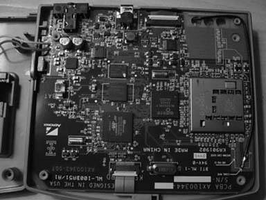
Near the brown LCD ribbon cable you should see three more Phillips-head screws. Two are connected to the metal pivot hinge. Leave those in place. Remove the third screw, which will release the small cap covering the ribbon cable and antenna feed. There was also a tiny pink plastic clip jammed into this space on my unit, putting pressure on the cables. Remove and discard it. Since we'll be adding a power cable for the backlight here, you won't have enough space for it, and since it just chafes the cables anyway, you won't miss it.
Now, here's the tricky part. Wedge a plastic screwdriver (or your thumbnail) between the two halves of the LCD side of the case and pry them apart.
Don't use a metal screwdriver; if you do, you'll leave nasty marks on the edge of the case. You have to pull pretty hard to unsnap the case, and directional pressure doesn't really help. Just yank the thing and it'll pop open.
Also, be careful when prying this apart not to lose the lid latch and spring. You can probably live without them, but if you want to keep them, now is your chance not to let them fly across the room or fall behind the workbench.
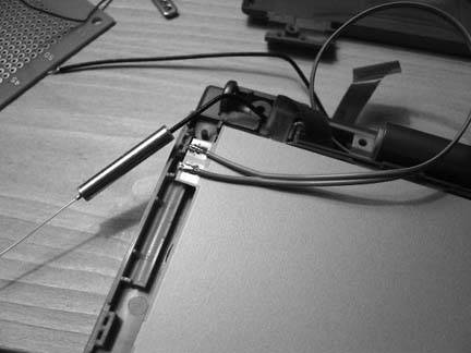
4.10.4. Removing the LCD Reflector
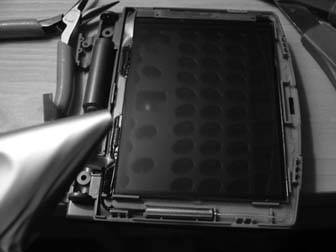
If all went well, you should see the white backing of the LCD panel, as well as more brown ribbon cable and the lid antenna, as shown in Figure 4-22. The white backing is held to the LCD with a sort of thick rubber cement. You need to peel this backing off and replace it with EL panel. The cement will stick to the LCD.
Figure 4-22. White LCD panel backing

Pick at a corner of the backing with a razor blade (or a fingernail). Try to peel off the backing all in one piece, pulling firmly away from the LCD. Keep in mind that the LCD is made of glass and is very, very fragile. You also don't want to touch the gummy cement with your fingers or any tools, since any marks you make in it will be visible when you install the backlight.
When the backing has been removed, it should look something like Figure 4-23.
Figure 4-23. LCD panel backing removed
4.10.5. Preparing and Installing the EL Panel
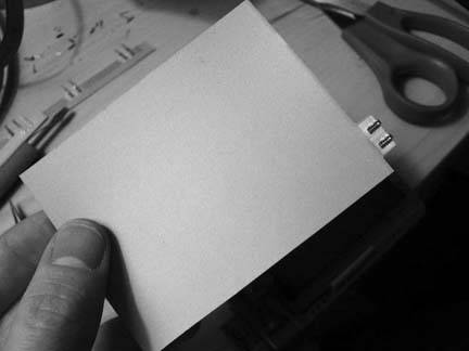
You should now be able to estimate how much EL panel you will need to cover the LCD. Trim yourself a nice piece using a pair of scissors. It should overlap the LCD panel on three sides by a couple of millimeters. On the side nearest the antenna, leave one set of leads and trim off the rest, as shown in Figure 4-24.
Figure 4-24. Trimming the EL panel to fit
Once you have trimmed the panel, place it gently on the LCD. I installed mine sort of like you install a piece of linoleum floor. You want to avoid air bubbles, so start in the middle and gently press the panel out towards the edges. Try to push any air bubbles all the way to the edge. If you trap a bubble, start over by pulling the panel all the way back off. This is easier than stripping the backing, since the panel is made of plastic. Remember, that's delicate glass you're pushing on, so don't press too hard.
4.10.6. Wiring
Solder a couple of wires to the leads on the EL panel, similar to Figure 4-25. I used ribbon wire salvaged from an old floppy disk cable. It should be at least eight or nine inches long, preferably stranded, and as thin as you can find (recycled CAT5 cable is way too thick). Remember that plastic will melt if you're not careful with your soldering, so be quick.
Figure 4-25. Soldering carefully
Run this wire the same way the antenna wire is run. Cover the exposed leads on the EL panel with a piece of electrical tape.
Flip the Zipit back over, and put the mainboard back in place. Feed the antenna cable and the two wires through the hole closest to the LCD panel connector.
Now comes the fun part: soldering the leads to the mainboard, as shown in Figure 4-26. Attach one wire each to the plus and minus poles on the battery connector. Solder a third wire to the corner pin on RP4, on the R108 side closest to C116.
Figure 4-26. Soldering the leads even more carefully

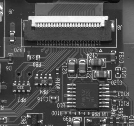
Figure 4-27 shows a detail with the proper pin labeled EN.
Figure 4-27. Detail with the pin labeled EN
Finally, reattach the antenna lead. When you're done, it should look like the unit shown in Figure 4-26. If your soldering iron isn't fine enough to solder the third wire, don't panic. This pin is pulled high when the LCD panel is active, so once we figure out power management on the board, this wire will turn the backlight on and off when the lid is closed. Of course, we haven't figured out power management as of this writing, so the backlight stays on all the time anyway under Linux. If you're running the Zipit messaging client, the backlight works beautifully and turns off to save battery time.
If you can't get this wire attached without destroying the board, just connect that wire directly to power and the backlight will stay lit all the time. It's not ideal, but it's better than nothing.
4.10.7. The Driver Board
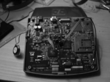
Now, solder in the EL panel driver board. The driver board from Jelu is based on the Supertex HV857MG driver (it's pretty much a nice little implementation of the reference design). I've noticed that this chip isn't designed to drive a panel as big as the one for our Zipit, so it ends up being a mellow blue instead of bright white. If you change the chip to an HV826 or HV830, it should be much brighter. I'll likely give that a try at some point. Figure 4-28 shows the finished unclosed case with a close-up of the driver board.
Figure 4-28. Jelu EL driver board
Connect LA and LB to your EL panel (it doesn't matter which is which), and connect GND to minus, VDD to plus, and EN to the remaining wire. At this point, you probably will want to connect the battery and power up the Zipit to be sure that everything works as expected. Don't touch the driver board while it's on, unless you are partial to electric shocks for fun.
If all went well, completely cover the driver board in electrical tape and carefully reassemble the Zipit. There's plenty of room for the driver board in the channel next to the battery compartment.
Congratulations! You can now use your Zipit in lighting other than direct bright sunlight!
4.10.8. Hacking the Hack
Removal is the reverse of installation.
I'm definitely going to try a different EL driver chip to get the brightness up a bit. But the Jelu model should get you going. These things are really neat; you typically need a big, whiney transformer to drive EL, but these driver chips are small, quiet, and efficient. A tiny driver board combined with a light that you can cut with scissors to any shape should make it easy to add a backlight to just about any transparent LCD display.
Bluetooth, Mobile Phones, and GPS
- Hacks 122: Introduction
- Hack 1. Set Up Bluetooth on Linux
- Hack 2. Set Up Bluetooth on Windows XP
- Hack 3. Connect Mac OS X with a Bluetooth Phone
- Hack 4. Connect Linux with a Bluetooth Phone
- Hack 5. Connect Windows XP with a Bluetooth Phone
- Hack 6. Use Your Treo as a Modem
- Hack 7. Send SMS from a PowerBook
- Hack 8. Remote Control Mac OS X with Bluetooth Phones and PDAs
- Hack 9. Remote Control Linux with a Bluetooth Phone
- Hack 10. Control XMMS with Bluetooth
- Hack 11. Liven Up Parties with a Participatory Slideshow
- Hack 12. Send SMS from Linux
- Hack 13. Remote Control Windows with Bluetooth Phones and PDAs
- Hack 14. Control Your Bluetooth Phone with FMA
- Hack 15. Control Your Computer from Your Palm
- Hack 16. Control Your Home Theater from Your Palm
- Hack 17. Choose a Cellular Data Plan
- Hack 18. Blog from Your Mobile Phone
- Hack 19. Get Google Maps on Your Mobile Phone
- Hack 20. Share Your GPS
- Hack 21. Broadcast Your GPS Position
- Hack 22. Map Wi-Fi Networks with Kismet and GPSd
Network Discovery and Monitoring
- Hacks 2339: Introduction
- Hack 23. Find All Available Wireless Networks
- Hack 24. Discover Networks with NetStumbler
- Hack 25. Detect Networks with Handheld PCs
- Hack 26. Find and Join Wireless Networks with AP Radar
- Hack 27. Detect Networks on Mac OS X
- Hack 28. Scan Passively with KisMAC
- Hack 29. Detect Networks with Kismet
- Hack 30. Monitor Wireless Links in Linux with Wavemon
- Hack 31. Analyze Traffic with Ethereal
- Hack 32. Track 802.11 Frames in Ethereal
- Hack 33. Watch Network Traffic
- Hack 34. grep Your Network
- Hack 35. Check Wi-Fi Network Performance with Qcheck
- Hack 36. Estimate Network Performance
- Hack 37. Get Real-Time Network Stats
- Hack 38. Graph Your Wireless Performance
- Hack 39. Find Radio Manufacturers by MAC
Wireless Security
- Hacks 4051: Introduction
- Hack 40. Stop Moochers from Stealing Your Wi-Fi Bandwidth
- Hack 41. Visualize a Network
- Hack 42. Secure Your Linux Network with WPA
- Hack 43. Control Wireless Access by MAC
- Hack 44. Authenticate Wireless Users
- Hack 45. Forward Ports over SSH
- Hack 46. Proxy Web Traffic over SSH
- Hack 47. Securely Connect Two Networks
- Hack 48. Generate a Tunnel Configuration Automatically
- Hack 49. Poll Wireless Clients
- Hack 50. Interrogate the Network
- Hack 51. Track Wireless Users
Hardware Hacks
- Hacks 5262: Introduction
- Hack 52. Add an External Antenna
- Hack 53. Do-It-Yourself Access Point Hardware
- Hack 54. Boot from a Compact Flash Hard Drive
- Hack 55. Increase the Range of a PowerBook
- Hack 56. Send Power over Your Ethernet
- Hack 57. The NoCat Night Light
- Hack 58. Upgrade the Linksys WET11
- Hack 59. Scan for Wireless Networks Automatically
- Hack 60. Backlight Your Zipit
- Hack 61. Unwire Your Pistol Mouse
- Hack 62. Mobilize Your WRT54G with the WiFiCar
Software Hacks
- Hacks 6382: Introduction
- Hack 63. Build Your Own Access Point with Linux
- Hack 64. Bridge Your Linux AP
- Hack 65. Protect Your Bridge with a Firewall
- Hack 66. Filter MAC with HostAP and Madwifi
- Hack 67. Upgrade Your Wireless Router
- Hack 68. Set Up an OLSR Mesh Network
- Hack 69. Extend Your Wireless Network with WDS
- Hack 70. Pebble
- Hack 71. Wall Off Your Wireless
- Hack 72. Run Your Mac as an Access Point
- Hack 73. Run Linux on the Zipit Wireless Messenger
- Hack 74. Capture Wireless Users with NoCatAuth
- Hack 75. Capture Wireless Users on a Small Scale
- Hack 76. Build an Online Community in Your Offline Neighborhood
- Hack 77. Manage Multiple AirPort Base Stations
- Hack 78. Advertise Bonjour Services in Linux
- Hack 79. Advertise Any Service with Bonjour in Mac OS X
- Hack 80. Redirect Brought to you by Bonjour Ads
- Hack 81. Use a Windows-Only Wireless Card in Linux
- Hack 82. Use Your Orinoco Card with Hermes AP
Do-It-Yourself Antennas
- Hacks 8393: Introduction
- Hack 83. Make a Deep Dish Cylindrical Parabolic Reflector
- Hack 84. Spider Omni Antenna
- Hack 85. Pringles Can Waveguide
- Hack 86. Pirouette Can Waveguide
- Hack 87. Primestar Dish with Waveguide Feed
- Hack 88. Primestar Dish with Biquad Feed
- Hack 89. Cut a Cable Omni Antenna
- Hack 90. Build a Slotted Waveguide Antenna
- Hack 91. The Passive Repeater
- Hack 92. Determine Your Antenna Gain
- Hack 93. Build Cheap, Effective Roof Mounts
Wireless Network Design
- Hacks 94100: Introduction
- Hack 94. Analyze Elevation Profiles for Better Long-Range Wireless Networking
- Hack 95. Build a Wireless Network for the Large House
- Hack 96. Establish Line of Sight
- Hack 97. Calculate the Link Budget
- Hack 98. Align Antennas at Long Distances
- Hack 99. Slow Down to Speed Up
- Hack 100. Take Advantage of Antenna Polarization
Appendix A. Wireless Standards
- Appendix A. Wireless Standards
- Section A.1. 802.11: The Mother of All IEEE Wireless Ethernet
- Section A.2. 802.11a: The Betamax of the 802.11 Family
- Section A.3. 802.11b: The De Facto Standard
- Section A.4. 802.11g: Like 802.11b, only Faster
- Section A.5. 802.16: WiMAX Long Distance Wireless Infrastructure
- Section A.6. Bluetooth: Cable Replacement for Devices
- Section A.7. 900 MHz: Low Speed, Better Coverage
- Section A.8. CDPD, 1xRTT, and GPRS: Cellular Data Networks
- Section A.9. FRS and GMRS: Super Walkie-Talkies
- Section A.10. 802.1x: Port Security for Network Communications
- Section A.11. WPA & 802.11i
- Section A.12. BSS Versus IBSS
Appendix B. Wireless Hardware Guide
EAN: 2147483647
Pages: 178
- Step 2.1 Use the OpenSSH Tool Suite to Replace Clear-Text Programs
- Step 3.2 Use PuTTY / plink as a Command Line Replacement for telnet / rlogin
- Step 3.3 Use WinSCP as a Graphical Replacement for FTP and RCP
- Step 3.4 Use PuTTYs Tools to Transfer Files from the Windows Command Line
- Step 4.1 Authentication with Public Keys
