Hack 62. Mobilize Your WRT54G with the WiFiCar


Why keep your wireless router in one place when you can give it wheels?
I've always thought that remote-controlled toy cars offer a great platform for other uses. For a while now, I've been thinking about how to put a small-form-factor PC motherboard on an RC car, but that would require quite a large car. When I stumbled upon OpenWRT [Hack #67], I realized that the WRT54G provided wireless, processing, and general-purpose I/O interface capabilities in one small package! With a wireless router mounted on a Wi-Ficontrollable car, you can patch holes in your wireless coverage, drive the car from any Internet terminal in the world, or a variety of other things that I couldn't think of right away. But I knew it would be cool. So I set off to mobilize my WRT54G.
There are two separate hacks that need to be done here: the software for the router, which will accept TCP connections and output the proper values to the GPIO pins, and the hardware, which will take those GPIO outputs and use that data to drive the car. Let's start with the software.
4.12.1. The Software
OpenWRT is a minimal Linux distribution for the Linksys WRT54G. The router still works as a router, which I think is impressive, while allowing you to tinker with things such as adding an SD card reader, adding an LCD, or whatever you want. For my hack, I borrowed code from the LED System Load Monitor and the SD Card Reader, both found on the OpenWRT web site (http://wiki.openwrt.org/OpenWrtDocs/Customizing). The SD Card Reader documentation identified GPIO pins on the router's circuit board, and the Load Monitor documentation provided a simple tool to control those pins.
I found a web site (http://pont.net/socket) that provides sample TCP socket server/client code written in C. After setting up a cross-compiler to compile programs for the router, I compiled this code and was pleased to see that it was working. I also tested the GPIO tool from the LED System Load Monitor to see that it also worked well on my router.
Then, I merged these two programs. My program modified the TCP server to send the output to my subroutine, which determines which byte was sent. If the byte is an ASCII digit, corresponding to values 4957 (zero is excluded), the program will set the GPIO pins so the car drives in the direction of that digit on a telephone keypad. Receiving a 1 makes the car drive forward-left, 2 is forward, 3 is forward-right, 4 is left, 5 is stop, 6 is right, 7 is back-left, 8 is back, and 9 is back-right. It took a while, but I eventually got that to work.
The complete C program follows.
|

/* fpont 1/00 */ /* pont.net */ #include #include #include #include #include #include #include /* close */ #include #define SUCCESS 0 #define ERROR 1 #define END_LINE 0x0 #define SERVER_PORT 1500 #define MAX_MSG 100 #define FORWARD 7 #define REVERSE 5 #define RIGHT 4 #define LEFT 3 int debug=0; /* function readline */ int read_line(); void enable(unsigned int pinset); void disable(unsigned int pinset); int poll(int pin); void processMsg(char *msg); int main (int argc, char *argv[]) { int sd, newSd, cliLen; struct sockaddr_in cliAddr, servAddr; char line[MAX_MSG]; /* create socket */ sd = socket(AF_INET, SOCK_STREAM, 0); if(sd<0) { perror("cannot open socket "); return ERROR; } /* bind server port */ servAddr.sin_family = AF_INET; servAddr.sin_addr.s_addr = htonl(INADDR_ANY); servAddr.sin_port = htons(SERVER_PORT); if(bind(sd, (struct sockaddr *) &servAddr, sizeof(servAddr))<0) { perror("cannot bind port "); return ERROR; } listen(sd,5); while(1) { printf("%s: waiting for data on port TCP %u
",argv[0],SERVER_PORT); cliLen = sizeof(cliAddr); newSd = accept(sd, (struct sockaddr *) &cliAddr, &cliLen); if(newSd<0) { perror("cannot accept connection "); return ERROR; } /* init line */ memset(line,0x0,MAX_MSG); /* receive segments */ while(read_line(newSd,line)!=ERROR) { printf("%s: received from %s:TCP%d : %s
", argv[0], inet_ntoa(cliAddr.sin_addr), ntohs(cliAddr.sin_port), line); /* init line */ processMsg(line); memset(line,0x0,MAX_MSG); } /* while(read_line) */ } /* while (1) */ } /* WARNING WARNING WARNING WARNING WARNING WARNING WARNING */ /* this function is experimental.. I don't know yet if it works */ /* correctly or not. Use Steven's readline( ) function to have */ /* something robust. */ /* WARNING WARNING WARNING WARNING WARNING WARNING WARNING */ /* rcv_line is my function readline( ). Data is read from the socket when */ /* needed, but not byte after bytes. All the received data is read. */ /* This means only one call to recv( ), instead of one call for */ /* each received byte. */ /* You can set END_CHAR to whatever means endofline for you. (0x0A is
)*/ /* read_lin returns the number of bytes returned in line_to_return */ int read_line(int newSd, char *line_to_return) { static int rcv_ptr=0; static char rcv_msg[MAX_MSG]; static int n; int offset; offset=0; while(1) { if(rcv_ptr==0) { /* read data from socket */ memset(rcv_msg,0x0,MAX_MSG); /* init buffer */ n = recv(newSd, rcv_msg, MAX_MSG, 0); /* wait for data */ if (n<0) { perror(" cannot receive data "); return ERROR; } else if (n==0) { printf(" connection closed by client
"); close(newSd); return ERROR; } } /* if new data read on socket */ /* OR */ /* if another line is still in buffer */ /* copy line into 'line_to_return' */ while(*(rcv_msg+rcv_ptr)!=END_LINE && rcv_ptr return line */ if(rcv_ptr==n-1) { /* set last byte to END_LINE */ *(line_to_return+offset)=END_LINE; rcv_ptr=0; return ++offset; } /* end of line but still some data in buffer => return line */ if(rcv_ptr */ /* wait for more data to arrive on socket */ if(rcv_ptr == n) { rcv_ptr = 0; } } /* while */ } void enable(unsigned int pinset) { unsigned int gpio; unsigned int pin=1<
To avoid typing numbers into an SSH connection, I wrote a small Visual Basic program to simplify sending data to the car. It uses the arrow keys on your keyboard to determine which data to send. I had trouble sending a null character from VB, but it works now. I tried porting it to eMbedded Visual Basic so that it runs from my PDA, but it, too, has trouble sending null characters. Once I get it to work, recall Q in James Bond, Tomorrow Never Dies: "Just push your finger gently across the pad to drive the car…."
So, that's the software component. The hardware proved every bit as challenging for an intermediate hacker like me. But if you're careful, you can avoid the mistakes that I made and save a few bucks.
4.12.2. The Hardware
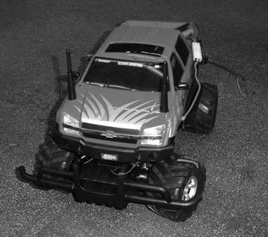
Our remote-control victim car is a Chevy Avalanche, shown in Figure 4-39, that I picked up for about $10 at the local Radio Shack. Its retail price is about $30; this one was cheap because it was a display model with no remote. Since the whole point of this hack is to replace the remote with Wi-Fi, it was an even better deal!
Figure 4-39. The Chevy Avalanche, post-operation
The router's GPIO pins can source only a few milliamps, but the drive motors of the car want up to two Amperes (amps) at stall. To convert between the low-power outputs of the router and the high-power needs of the car, Bell Laboratories invented the transistor in 1947 to do exactly that.
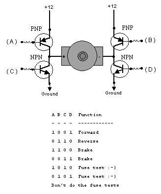
However, a transistor can provide only high-voltage (known as logic high) or low-voltage (known as logic low), but not both. The motors will need one side high and one side low to drive forward, and the reverse of that to drive backwards. So, each side of the motor must have a high-side transistor (known as PNP), and a low side transistor (known as NPN). When connected together, the schematic looks something like the letter H with a transistor on each leg and the motor in the middle, as shown in Figure 4-40.
It is possible to build this schematic from scratch, using eight transistors to drive two motors. However, this is unnecessarily complicated in the Integrated Circuit age. For a few bucks, you can get all this in a neat little package. I used the SN754410, available from Acroname for five dollars at http://www.acroname.com/robotics/parts/R6-754410.html. Fortunately, I ordered three.
Figure 4-40. Schematic for the driver
Using a small proto-board and five-volt regulator model 7805 (http://tinyurl.com/wqbv) from Radio Shack, I put together a small driver board. It had 10 wires coming out of it: two power wires connected directly to the drive battery, and four small wires connected to a telephone connector that plugged into the router (so the router wasn't soldered to the car).
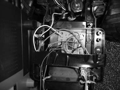
The drive motors, however, were soldered directly to the board, providing the last four wires that came into the board. The first time I powered it up, I was sure to test all the connections, because I felt something bad would happen. It did; I made sure that the power wires were indeed the power wires, but I forgot to check the polarity! The chip went up in smoke, leaving charred remains. Undaunted, I rebuilt the circuit with one of the other chips that I ordered and, finally, the driver board worked. Figure 4-41 shows the finished driver board installed inside the Chevy.
I taped the router to the bare base of the car to test it out; it worked! It looked ugly, but after connecting to the car's access point, using an SSH client to start the RC car server program rcServ, and loading my VB client, the car moved! I could have finished there, but I decided to see if it could work with the Chevy Avalanche cover on, just for looks.
Figure 4-41. Installed driver board
A friend of mine, Manny, decided to take it upon himself to do this part. Using a dremel, he cut holes in the side of the case for the legs of the router, and also two holes up front for the antennas. Although I calculated that the car would work up to a hundred feet without the antennas, he decided to put the holes in, anyway. Given that it was his first time using the tool, results were as expected: the case still has to be stretched to fit the router, and even so it scratches the sides, as well as the antennas.
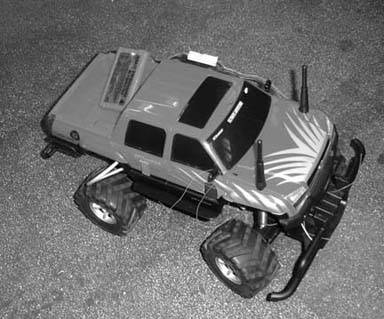
Needless to say, the blue and black protrusions in the side of the red car are also an eyesore. Although it is better than without the cover, I would have chosen a better way to fit the router inside the case. Hey, if you want something done right, you have to do it yourself. But, as shown in Figure 4-42, it does look cool!
Here's the final result: the WiFiCar. It's far from perfect, but it does provide a base from which to expand; many people have contacted me about adding cameras, GPS, autonomy, and various other additions to the car. I'm also working on a bigger version using a 1/6th scale Hummer. But this is, to my knowledge, the first self-controlled wireless router.
Figure 4-42. The finished WiFiCar
|
Yasha Okshtein
Bluetooth, Mobile Phones, and GPS
- Hacks 122: Introduction
- Hack 1. Set Up Bluetooth on Linux
- Hack 2. Set Up Bluetooth on Windows XP
- Hack 3. Connect Mac OS X with a Bluetooth Phone
- Hack 4. Connect Linux with a Bluetooth Phone
- Hack 5. Connect Windows XP with a Bluetooth Phone
- Hack 6. Use Your Treo as a Modem
- Hack 7. Send SMS from a PowerBook
- Hack 8. Remote Control Mac OS X with Bluetooth Phones and PDAs
- Hack 9. Remote Control Linux with a Bluetooth Phone
- Hack 10. Control XMMS with Bluetooth
- Hack 11. Liven Up Parties with a Participatory Slideshow
- Hack 12. Send SMS from Linux
- Hack 13. Remote Control Windows with Bluetooth Phones and PDAs
- Hack 14. Control Your Bluetooth Phone with FMA
- Hack 15. Control Your Computer from Your Palm
- Hack 16. Control Your Home Theater from Your Palm
- Hack 17. Choose a Cellular Data Plan
- Hack 18. Blog from Your Mobile Phone
- Hack 19. Get Google Maps on Your Mobile Phone
- Hack 20. Share Your GPS
- Hack 21. Broadcast Your GPS Position
- Hack 22. Map Wi-Fi Networks with Kismet and GPSd
Network Discovery and Monitoring
- Hacks 2339: Introduction
- Hack 23. Find All Available Wireless Networks
- Hack 24. Discover Networks with NetStumbler
- Hack 25. Detect Networks with Handheld PCs
- Hack 26. Find and Join Wireless Networks with AP Radar
- Hack 27. Detect Networks on Mac OS X
- Hack 28. Scan Passively with KisMAC
- Hack 29. Detect Networks with Kismet
- Hack 30. Monitor Wireless Links in Linux with Wavemon
- Hack 31. Analyze Traffic with Ethereal
- Hack 32. Track 802.11 Frames in Ethereal
- Hack 33. Watch Network Traffic
- Hack 34. grep Your Network
- Hack 35. Check Wi-Fi Network Performance with Qcheck
- Hack 36. Estimate Network Performance
- Hack 37. Get Real-Time Network Stats
- Hack 38. Graph Your Wireless Performance
- Hack 39. Find Radio Manufacturers by MAC
Wireless Security
- Hacks 4051: Introduction
- Hack 40. Stop Moochers from Stealing Your Wi-Fi Bandwidth
- Hack 41. Visualize a Network
- Hack 42. Secure Your Linux Network with WPA
- Hack 43. Control Wireless Access by MAC
- Hack 44. Authenticate Wireless Users
- Hack 45. Forward Ports over SSH
- Hack 46. Proxy Web Traffic over SSH
- Hack 47. Securely Connect Two Networks
- Hack 48. Generate a Tunnel Configuration Automatically
- Hack 49. Poll Wireless Clients
- Hack 50. Interrogate the Network
- Hack 51. Track Wireless Users
Hardware Hacks
- Hacks 5262: Introduction
- Hack 52. Add an External Antenna
- Hack 53. Do-It-Yourself Access Point Hardware
- Hack 54. Boot from a Compact Flash Hard Drive
- Hack 55. Increase the Range of a PowerBook
- Hack 56. Send Power over Your Ethernet
- Hack 57. The NoCat Night Light
- Hack 58. Upgrade the Linksys WET11
- Hack 59. Scan for Wireless Networks Automatically
- Hack 60. Backlight Your Zipit
- Hack 61. Unwire Your Pistol Mouse
- Hack 62. Mobilize Your WRT54G with the WiFiCar
Software Hacks
- Hacks 6382: Introduction
- Hack 63. Build Your Own Access Point with Linux
- Hack 64. Bridge Your Linux AP
- Hack 65. Protect Your Bridge with a Firewall
- Hack 66. Filter MAC with HostAP and Madwifi
- Hack 67. Upgrade Your Wireless Router
- Hack 68. Set Up an OLSR Mesh Network
- Hack 69. Extend Your Wireless Network with WDS
- Hack 70. Pebble
- Hack 71. Wall Off Your Wireless
- Hack 72. Run Your Mac as an Access Point
- Hack 73. Run Linux on the Zipit Wireless Messenger
- Hack 74. Capture Wireless Users with NoCatAuth
- Hack 75. Capture Wireless Users on a Small Scale
- Hack 76. Build an Online Community in Your Offline Neighborhood
- Hack 77. Manage Multiple AirPort Base Stations
- Hack 78. Advertise Bonjour Services in Linux
- Hack 79. Advertise Any Service with Bonjour in Mac OS X
- Hack 80. Redirect Brought to you by Bonjour Ads
- Hack 81. Use a Windows-Only Wireless Card in Linux
- Hack 82. Use Your Orinoco Card with Hermes AP
Do-It-Yourself Antennas
- Hacks 8393: Introduction
- Hack 83. Make a Deep Dish Cylindrical Parabolic Reflector
- Hack 84. Spider Omni Antenna
- Hack 85. Pringles Can Waveguide
- Hack 86. Pirouette Can Waveguide
- Hack 87. Primestar Dish with Waveguide Feed
- Hack 88. Primestar Dish with Biquad Feed
- Hack 89. Cut a Cable Omni Antenna
- Hack 90. Build a Slotted Waveguide Antenna
- Hack 91. The Passive Repeater
- Hack 92. Determine Your Antenna Gain
- Hack 93. Build Cheap, Effective Roof Mounts
Wireless Network Design
- Hacks 94100: Introduction
- Hack 94. Analyze Elevation Profiles for Better Long-Range Wireless Networking
- Hack 95. Build a Wireless Network for the Large House
- Hack 96. Establish Line of Sight
- Hack 97. Calculate the Link Budget
- Hack 98. Align Antennas at Long Distances
- Hack 99. Slow Down to Speed Up
- Hack 100. Take Advantage of Antenna Polarization
Appendix A. Wireless Standards
- Appendix A. Wireless Standards
- Section A.1. 802.11: The Mother of All IEEE Wireless Ethernet
- Section A.2. 802.11a: The Betamax of the 802.11 Family
- Section A.3. 802.11b: The De Facto Standard
- Section A.4. 802.11g: Like 802.11b, only Faster
- Section A.5. 802.16: WiMAX Long Distance Wireless Infrastructure
- Section A.6. Bluetooth: Cable Replacement for Devices
- Section A.7. 900 MHz: Low Speed, Better Coverage
- Section A.8. CDPD, 1xRTT, and GPRS: Cellular Data Networks
- Section A.9. FRS and GMRS: Super Walkie-Talkies
- Section A.10. 802.1x: Port Security for Network Communications
- Section A.11. WPA & 802.11i
- Section A.12. BSS Versus IBSS
Appendix B. Wireless Hardware Guide
EAN: 2147483647
Pages: 178
