Hack 85. Pringles Can Waveguide


Here's how to make the infamous Pringles cantenna.
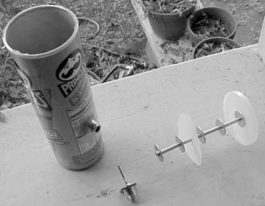
At the Portland Summit in June 2001, Andrew Clapp presented a novel yagi antenna design (http://www.aeonic.com/~clapp/wireless). It used a bolt, metal tubing, washers, and PVC tubing to make an inexpensive shotgun yagi, either 18" or 36" long. While his antenna shows between 12 and 15 dBi gain (which is impressive for such a simple design), it's also quite large. When we returned from Portland, some members of our local group realized that, if we were careful, we could fit a full wavelength inside of a Pringles can (see Figure 6-5). This would show a reduced total gain, but it would also make the entire antenna much more compact.
This now infamous hack takes about an hour to construct. Table 6-1 shows a list of the parts you need to get started.
Figure 6-5. The complete Pringles can antenna
|
Part |
Approximate cost |
|---|---|
|
All-thread, 5 5/8" long, 1/8" OD |
$1.00 |
|
Two nylon lock nuts |
$0.10 |
|
Five 1" washers, 1/8" ID |
$0.10 |
|
6" aluminum tubing, 1/4" ID |
$0.75 |
|
A connector to match your radio pigtail or antenna cable (we used a female N connector) |
$3.00 |
|
One 1/2" piece of 12-gauge solid copper wire (we used ground wire from house electrical wiring) |
Negligible |
|
A tall Pringles can (any flavor, Ridges are optional) |
$1.50 |
|
Scrap plastic disc, 3" across (for example, another Pringles can lid) |
Negligible |
|
Total: |
$6.45 |
Of course, buying in bulk helps a lot. You probably won't be able to find a 6" piece of all-thread; buy the standard size (usually one or two feet) and a 10-pack of washers and nuts while you're at it. Then you'll have more than enough parts to make two antennas, all for about $10.
You'll also need the following tools:
- Ruler
- Scissors
- Pipe cutter (or hacksaw or dremel tool, in a pinch)
- Heavy-duty cutters (or dremel again, to cut the all-thread)
- Something sharp to pierce the plastic (such as an awl or a drill bit)
- Hot glue gun (unless you have a screw-down type connector)
- Soldering iron
6.4.1. Front Collector Construction
Mark and cut four pieces of tubing, about 1.2" (1 15/64"). Where did I get this number? First figure out the wavelength at the bottom of the frequency range we're using (2.412 GHz, or Channel One). This will be the longest that the pipe should be:
	W = 3.0 * 10^8 * (1 / 2.412) * 10^-9
	W = (3.0 / 2.412) * 10^-1
	W = 0.124 meters
	W = 4.88 inches
We'll be cutting the pipe to quarter wavelength, so:
	1/4 W = 4.88 / 4
	1/4 W = 1.22"
Now, figure out what the shortest range we'll ever use is (2.462 GHz, or channel 11 in the United States):
	W = 3.0 * 10^8 * (1 / 2.462) * 10^-9
	W = (3.0 / 2.462) * 10^-1
	W = 0.122 meters
	W = 4.80 inches
	1/4 W = 1.20"
Practically speaking, what's the difference between the shortest pipe and the longest pipe length? The answer is about 0.02" or less than 1/32". That's probably about the size of the pipe cutter blade you're using. So, just shoot for 1.2" and you'll get it close enough.
Cut the all-thread to exactly 5 5/8". The washers we used are about 1/16" thick, so that should leave just enough room for the pipe, washers, and nuts.
Pierce a hole in the center of the Pringles can lid big enough for the all-thread to pass through. Now is probably a good time to start eating Pringles.
|

Cut a 3" plastic disc, just big enough to fit snugly inside the can. We found that another Pringles lid, with the outer ridge trimmed off, works just fine. Poke a hole in the center of it, and slip it over one of the lengths of pipe.
Now, assemble the pipe. You might have to use a file or dremel tool to shave the tips of the thread, if you have trouble getting the nuts on. The pipe is a sandwich that goes on the all-thread like this:
Nut
images/U2192.jpg border=0> Lid
You can see the collector assembly clearly in Figure 6-5. Tighten down the nuts to be snug, but don't overtighten (I bent the tubing on our first try; aluminum bends very easily). Just get it snug. Congratulations; you now you have the front collector.
6.4.2. Preparing the Can
By now, you should have eaten (or tossed) the actual chips. Wipe out the can, and measure 3 3/8" up from the bottom of the can. Cut a hole just big enough for the connector to pass through. We found through trial and error that this seems to be the sweet spot of the can. On our Pringles "Salt & Vinegar" can, the N connector sat directly between "Sodium" and "Protein."
6.4.3. Element Construction
Straighten the heavy copper wire and solder it to the connector. When inside the can, the wire should be just below its midpoint (ours turned out to be about 1 1/16"). You lose a few dB by going longer, so cut it just shy of the middle of the can.
We were in a hurry, so we used hot glue to hold the connector in place on our first antenna. If you have a connector that uses a nut and washer, and you're really careful about cutting the hole, these work very well (and aren't nearly as messy as hot glue). Just remember that you're screwing into cardboard when you connect your pigtail. It's easy to forget and accidentally tear the wall of the can.
Now, insert the collector assembly into the can and close the lid. The inside end of the pipe should not touch the copper element; it should be just forward of it. If it touches, your all-thread is probably too long.
How can you estimate gain without access to high-end radio analysis gear? Using the Link Test software that comes with the Orinoco Silver cards, you can see the signal and noise readings (in dB) of a received signal, as well as your test partner's reception of your signal. As I happen to live 0.6 mile (with clean line of sight) from O'Reilly headquarters, we had a fairly controlled test bed to experiment with. We shot at the omni on the roof and used the access point at O'Reilly as our link test partner.
To estimate antenna performance, we started by connecting commercial antennas of known gain and taking readings. Then, we connected our test antennas and compared the results. We had the following at our disposal:
- Two 10 dBi, 180-degree sector panel antennas
- One 11 dBi, 120-degree sector panel antenna
- One 24 dBi parabolic dish
- The Pringles can antenna
Table 6-2 shows the average received signal and noise readings from each, in approximately the same physical position.
|
Antenna |
Signal |
Noise |
|---|---|---|
|
10dBi A |
-83db |
-92db |
|
10dBi B |
-83db |
-92db |
|
11dBi |
-82db |
-95db |
|
24dBi |
-67db |
-102db |
|
Pringles can |
-81db |
-98db |
The test partner (AP side) signal results were virtually the same. Interestingly, even at only 0.6 mile, we saw some thermal fade effect; as the evening turned into night, we saw about a 3 dB gain across the board.
|
Yagis and dishes are much more directional than sectors and omnis. This bore out in the numbers, as the perceived noise level was consistently lower with the more directional antennas. This can help a lot on long-distance shots, as not only will your perceived signal be greater, but the competing noise will also seem to be less. More directional antennas also help keep noise down for your neighbors trying to share the spectrum as well. Be a good neighbor and use the most directional antennas that will work for your application (yes, noise is everybody's problem).
The Pringles can seemed to have large side lobes that extend about 45 degrees from the center of the can. Don't point the can directly at where you're trying to go; instead, aim slightly to the left or the right. We also found that elevating the antenna helped a bit as well. When aiming the antenna, hold it behind the connector, and slowly sweep from left to right, with the Link Test program running. When you get the maximum signal, slowly raise the end of the can to see whether it makes a difference. Go slowly, changing only one variable at a time.
Remember that the can is polarized, so match the phase of the antenna you're talking to (for example, if shooting at an omni, be sure the element is on the bottom or the top of the can; otherwise, you won't be able to see it). See [Hack #100] for how you can use this effect to your advantage.
We were fortunate enough to have a member of our community group bring a return loss meter to one of our meetings, and were able to get some actual measurements of how much signal was returning to the radio. The results weren't as good as I had hoped, but they showed that the antenna was usable, particularly at lower frequencies. Most likely, failing to take into account the thickness of the washers made the entire front element a little too long. There isn't nearly enough power leaving the radio to cause damage due to high return loss, but it does point out that the antenna isn't as well-tuned as it could be.
For a simpler, higher-gain waveguide antenna, read "Pirouette Can Waveguide" [Hack #86].
|
Bluetooth, Mobile Phones, and GPS
- Hacks 122: Introduction
- Hack 1. Set Up Bluetooth on Linux
- Hack 2. Set Up Bluetooth on Windows XP
- Hack 3. Connect Mac OS X with a Bluetooth Phone
- Hack 4. Connect Linux with a Bluetooth Phone
- Hack 5. Connect Windows XP with a Bluetooth Phone
- Hack 6. Use Your Treo as a Modem
- Hack 7. Send SMS from a PowerBook
- Hack 8. Remote Control Mac OS X with Bluetooth Phones and PDAs
- Hack 9. Remote Control Linux with a Bluetooth Phone
- Hack 10. Control XMMS with Bluetooth
- Hack 11. Liven Up Parties with a Participatory Slideshow
- Hack 12. Send SMS from Linux
- Hack 13. Remote Control Windows with Bluetooth Phones and PDAs
- Hack 14. Control Your Bluetooth Phone with FMA
- Hack 15. Control Your Computer from Your Palm
- Hack 16. Control Your Home Theater from Your Palm
- Hack 17. Choose a Cellular Data Plan
- Hack 18. Blog from Your Mobile Phone
- Hack 19. Get Google Maps on Your Mobile Phone
- Hack 20. Share Your GPS
- Hack 21. Broadcast Your GPS Position
- Hack 22. Map Wi-Fi Networks with Kismet and GPSd
Network Discovery and Monitoring
- Hacks 2339: Introduction
- Hack 23. Find All Available Wireless Networks
- Hack 24. Discover Networks with NetStumbler
- Hack 25. Detect Networks with Handheld PCs
- Hack 26. Find and Join Wireless Networks with AP Radar
- Hack 27. Detect Networks on Mac OS X
- Hack 28. Scan Passively with KisMAC
- Hack 29. Detect Networks with Kismet
- Hack 30. Monitor Wireless Links in Linux with Wavemon
- Hack 31. Analyze Traffic with Ethereal
- Hack 32. Track 802.11 Frames in Ethereal
- Hack 33. Watch Network Traffic
- Hack 34. grep Your Network
- Hack 35. Check Wi-Fi Network Performance with Qcheck
- Hack 36. Estimate Network Performance
- Hack 37. Get Real-Time Network Stats
- Hack 38. Graph Your Wireless Performance
- Hack 39. Find Radio Manufacturers by MAC
Wireless Security
- Hacks 4051: Introduction
- Hack 40. Stop Moochers from Stealing Your Wi-Fi Bandwidth
- Hack 41. Visualize a Network
- Hack 42. Secure Your Linux Network with WPA
- Hack 43. Control Wireless Access by MAC
- Hack 44. Authenticate Wireless Users
- Hack 45. Forward Ports over SSH
- Hack 46. Proxy Web Traffic over SSH
- Hack 47. Securely Connect Two Networks
- Hack 48. Generate a Tunnel Configuration Automatically
- Hack 49. Poll Wireless Clients
- Hack 50. Interrogate the Network
- Hack 51. Track Wireless Users
Hardware Hacks
- Hacks 5262: Introduction
- Hack 52. Add an External Antenna
- Hack 53. Do-It-Yourself Access Point Hardware
- Hack 54. Boot from a Compact Flash Hard Drive
- Hack 55. Increase the Range of a PowerBook
- Hack 56. Send Power over Your Ethernet
- Hack 57. The NoCat Night Light
- Hack 58. Upgrade the Linksys WET11
- Hack 59. Scan for Wireless Networks Automatically
- Hack 60. Backlight Your Zipit
- Hack 61. Unwire Your Pistol Mouse
- Hack 62. Mobilize Your WRT54G with the WiFiCar
Software Hacks
- Hacks 6382: Introduction
- Hack 63. Build Your Own Access Point with Linux
- Hack 64. Bridge Your Linux AP
- Hack 65. Protect Your Bridge with a Firewall
- Hack 66. Filter MAC with HostAP and Madwifi
- Hack 67. Upgrade Your Wireless Router
- Hack 68. Set Up an OLSR Mesh Network
- Hack 69. Extend Your Wireless Network with WDS
- Hack 70. Pebble
- Hack 71. Wall Off Your Wireless
- Hack 72. Run Your Mac as an Access Point
- Hack 73. Run Linux on the Zipit Wireless Messenger
- Hack 74. Capture Wireless Users with NoCatAuth
- Hack 75. Capture Wireless Users on a Small Scale
- Hack 76. Build an Online Community in Your Offline Neighborhood
- Hack 77. Manage Multiple AirPort Base Stations
- Hack 78. Advertise Bonjour Services in Linux
- Hack 79. Advertise Any Service with Bonjour in Mac OS X
- Hack 80. Redirect Brought to you by Bonjour Ads
- Hack 81. Use a Windows-Only Wireless Card in Linux
- Hack 82. Use Your Orinoco Card with Hermes AP
Do-It-Yourself Antennas
- Hacks 8393: Introduction
- Hack 83. Make a Deep Dish Cylindrical Parabolic Reflector
- Hack 84. Spider Omni Antenna
- Hack 85. Pringles Can Waveguide
- Hack 86. Pirouette Can Waveguide
- Hack 87. Primestar Dish with Waveguide Feed
- Hack 88. Primestar Dish with Biquad Feed
- Hack 89. Cut a Cable Omni Antenna
- Hack 90. Build a Slotted Waveguide Antenna
- Hack 91. The Passive Repeater
- Hack 92. Determine Your Antenna Gain
- Hack 93. Build Cheap, Effective Roof Mounts
Wireless Network Design
- Hacks 94100: Introduction
- Hack 94. Analyze Elevation Profiles for Better Long-Range Wireless Networking
- Hack 95. Build a Wireless Network for the Large House
- Hack 96. Establish Line of Sight
- Hack 97. Calculate the Link Budget
- Hack 98. Align Antennas at Long Distances
- Hack 99. Slow Down to Speed Up
- Hack 100. Take Advantage of Antenna Polarization
Appendix A. Wireless Standards
- Appendix A. Wireless Standards
- Section A.1. 802.11: The Mother of All IEEE Wireless Ethernet
- Section A.2. 802.11a: The Betamax of the 802.11 Family
- Section A.3. 802.11b: The De Facto Standard
- Section A.4. 802.11g: Like 802.11b, only Faster
- Section A.5. 802.16: WiMAX Long Distance Wireless Infrastructure
- Section A.6. Bluetooth: Cable Replacement for Devices
- Section A.7. 900 MHz: Low Speed, Better Coverage
- Section A.8. CDPD, 1xRTT, and GPRS: Cellular Data Networks
- Section A.9. FRS and GMRS: Super Walkie-Talkies
- Section A.10. 802.1x: Port Security for Network Communications
- Section A.11. WPA & 802.11i
- Section A.12. BSS Versus IBSS
Appendix B. Wireless Hardware Guide
EAN: 2147483647
Pages: 178
