Hack 56. Send Power over Your Ethernet


Power your access point without a separate power cable by using free pairs on CAT5.
A number of access point manufacturers (Proxim, Symbol, and D-Link, to name just three) are now offering Power over Ethernet (PoE) add-ons for their access points. PoE modules insert DC voltage into a standard Ethernet cable. The idea is to supply the AP's power and UTP Ethernet connectivity requirements via a single Ethernet cable.
This works great in areas where you might not have power easily accessible, such as a roof. This also allows you to more easily place the AP closer to the antenna, thus reducing signal loss over antenna cabling. Ethernet signal travels well over CAT5 cable; a 2.4 GHz signal doesn't do as well over antenna cabling. Also, Ethernet cabling is much cheaper than antenna cable such as LMR400. This hack demonstrates how to build a simple PoE module pair.
In June 2003, the IEEE ratified the 802.3af standard for Power over Ethernet, which has spurred the release of standards-compliant PoE products. 802.3af defines two types of power source equipment: end-span and mid-span devices. An end-span device is an Ethernet switch with embedded PoE technology. These switches deliver data and power over the same wiring pairs: 1/2 and 3/6.
We're going to build a pair of mid-span devices, which in the 802.3af specification can be placed between a legacy switch and the device to be powered. A mid-span device has an RJ-45 data input and a power input, and it sends the data on pairs 1/2and 3/6, while sending power on the unused 4/5 and 7/8 pairs.
4.6.1. Step by Step
If you have a device such as a VoIP phone or a Soekris PC that will accept Power over Ethernet without a secondary adapter, you will only need to build the power injector in steps 13.
|

- Solder wires to the DC Male Power Plug. Solder one pair (two wires twisted together) to the inner-contact connection. These will be the positive power wires. Solder another pair to the outer-contact connection. Notice that there are three connectors on this DC male power plug. One is for the center pin, one is for the outer surface, and one goes to the plug housing. You do not need to solder anything to the plug-housing connector. Figure 4-6 shows what it should look like when finished.
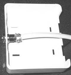
- Drill a hole in your two-port mount housing. Mount the male DC plug in the housing, as shown in Figure 4-7.
Figure 4-6. The completed power plug
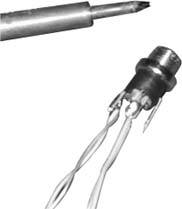
Figure 4-7. The DC plug mounted in the housing
- Connect the wires in your two-port jack as follows:
Table 4-1.
Input jack
Output jack
DC plug
Pin 1
<-> Pin 1
Pin 2
<-> Pin 2
Pin 3
<-> Pin 3
Pin 4 <->
DC Positive Wire 1
 Center Connector
Pin 5 <->
DC Positive Wire 2
Center ConnectorPin 6 <-> Pin 6
Pin 7
<-> DC Negative Wire 1
Outer ConnectorPin 8
<-> DC Negative Wire 2
Outer Connector - Table 4-2.
Output plug
Input jack
DC plug
Pin 1
<-> Pin 1
Pin 2
<-> Pin 2
Pin 3
<-> Pin 3
Pin 4
<-> DC Positive Wire 1
Center ConnectorPin 5
<-> DC Positive Wire 2
Pin 6 Center Connector<-> Pin 6
Pin 7
<-> DC Negative Wire 1
Outer ConnectorPin 8
<-> DC Negative Wire 2
Outer Connector -
4.6.2. Resistance Is Futile
The DC resistance of CAT5 is about 3 ohms per 100 feet per conductor, so a 250-foot cable has at least 7 ohms resistance. Most of the time, an AP draws much less than 0.8A, so you would still be above 6V at the AP. In fact, the access points typically use linear regulators to drop the voltage down to 5V on their insides, so as long as you're giving them something better than 6V at the terminals, they're likely to work.
There is a good calculator online at http://www.gweep.net/~sfoskett/tech/poecalc.html that calculates the voltage drop for a given length of CAT5. Use it to estimate how much power you need to provide at one end of your cable run in order to power your access point.
Terry Schmidt
Bluetooth, Mobile Phones, and GPS
- Hacks 122: Introduction
- Hack 1. Set Up Bluetooth on Linux
- Hack 2. Set Up Bluetooth on Windows XP
- Hack 3. Connect Mac OS X with a Bluetooth Phone
- Hack 4. Connect Linux with a Bluetooth Phone
- Hack 5. Connect Windows XP with a Bluetooth Phone
- Hack 6. Use Your Treo as a Modem
- Hack 7. Send SMS from a PowerBook
- Hack 8. Remote Control Mac OS X with Bluetooth Phones and PDAs
- Hack 9. Remote Control Linux with a Bluetooth Phone
- Hack 10. Control XMMS with Bluetooth
- Hack 11. Liven Up Parties with a Participatory Slideshow
- Hack 12. Send SMS from Linux
- Hack 13. Remote Control Windows with Bluetooth Phones and PDAs
- Hack 14. Control Your Bluetooth Phone with FMA
- Hack 15. Control Your Computer from Your Palm
- Hack 16. Control Your Home Theater from Your Palm
- Hack 17. Choose a Cellular Data Plan
- Hack 18. Blog from Your Mobile Phone
- Hack 19. Get Google Maps on Your Mobile Phone
- Hack 20. Share Your GPS
- Hack 21. Broadcast Your GPS Position
- Hack 22. Map Wi-Fi Networks with Kismet and GPSd
Network Discovery and Monitoring
- Hacks 2339: Introduction
- Hack 23. Find All Available Wireless Networks
- Hack 24. Discover Networks with NetStumbler
- Hack 25. Detect Networks with Handheld PCs
- Hack 26. Find and Join Wireless Networks with AP Radar
- Hack 27. Detect Networks on Mac OS X
- Hack 28. Scan Passively with KisMAC
- Hack 29. Detect Networks with Kismet
- Hack 30. Monitor Wireless Links in Linux with Wavemon
- Hack 31. Analyze Traffic with Ethereal
- Hack 32. Track 802.11 Frames in Ethereal
- Hack 33. Watch Network Traffic
- Hack 34. grep Your Network
- Hack 35. Check Wi-Fi Network Performance with Qcheck
- Hack 36. Estimate Network Performance
- Hack 37. Get Real-Time Network Stats
- Hack 38. Graph Your Wireless Performance
- Hack 39. Find Radio Manufacturers by MAC
Wireless Security
- Hacks 4051: Introduction
- Hack 40. Stop Moochers from Stealing Your Wi-Fi Bandwidth
- Hack 41. Visualize a Network
- Hack 42. Secure Your Linux Network with WPA
- Hack 43. Control Wireless Access by MAC
- Hack 44. Authenticate Wireless Users
- Hack 45. Forward Ports over SSH
- Hack 46. Proxy Web Traffic over SSH
- Hack 47. Securely Connect Two Networks
- Hack 48. Generate a Tunnel Configuration Automatically
- Hack 49. Poll Wireless Clients
- Hack 50. Interrogate the Network
- Hack 51. Track Wireless Users
Hardware Hacks
- Hacks 5262: Introduction
- Hack 52. Add an External Antenna
- Hack 53. Do-It-Yourself Access Point Hardware
- Hack 54. Boot from a Compact Flash Hard Drive
- Hack 55. Increase the Range of a PowerBook
- Hack 56. Send Power over Your Ethernet
- Hack 57. The NoCat Night Light
- Hack 58. Upgrade the Linksys WET11
- Hack 59. Scan for Wireless Networks Automatically
- Hack 60. Backlight Your Zipit
- Hack 61. Unwire Your Pistol Mouse
- Hack 62. Mobilize Your WRT54G with the WiFiCar
Software Hacks
- Hacks 6382: Introduction
- Hack 63. Build Your Own Access Point with Linux
- Hack 64. Bridge Your Linux AP
- Hack 65. Protect Your Bridge with a Firewall
- Hack 66. Filter MAC with HostAP and Madwifi
- Hack 67. Upgrade Your Wireless Router
- Hack 68. Set Up an OLSR Mesh Network
- Hack 69. Extend Your Wireless Network with WDS
- Hack 70. Pebble
- Hack 71. Wall Off Your Wireless
- Hack 72. Run Your Mac as an Access Point
- Hack 73. Run Linux on the Zipit Wireless Messenger
- Hack 74. Capture Wireless Users with NoCatAuth
- Hack 75. Capture Wireless Users on a Small Scale
- Hack 76. Build an Online Community in Your Offline Neighborhood
- Hack 77. Manage Multiple AirPort Base Stations
- Hack 78. Advertise Bonjour Services in Linux
- Hack 79. Advertise Any Service with Bonjour in Mac OS X
- Hack 80. Redirect Brought to you by Bonjour Ads
- Hack 81. Use a Windows-Only Wireless Card in Linux
- Hack 82. Use Your Orinoco Card with Hermes AP
Do-It-Yourself Antennas
- Hacks 8393: Introduction
- Hack 83. Make a Deep Dish Cylindrical Parabolic Reflector
- Hack 84. Spider Omni Antenna
- Hack 85. Pringles Can Waveguide
- Hack 86. Pirouette Can Waveguide
- Hack 87. Primestar Dish with Waveguide Feed
- Hack 88. Primestar Dish with Biquad Feed
- Hack 89. Cut a Cable Omni Antenna
- Hack 90. Build a Slotted Waveguide Antenna
- Hack 91. The Passive Repeater
- Hack 92. Determine Your Antenna Gain
- Hack 93. Build Cheap, Effective Roof Mounts
Wireless Network Design
- Hacks 94100: Introduction
- Hack 94. Analyze Elevation Profiles for Better Long-Range Wireless Networking
- Hack 95. Build a Wireless Network for the Large House
- Hack 96. Establish Line of Sight
- Hack 97. Calculate the Link Budget
- Hack 98. Align Antennas at Long Distances
- Hack 99. Slow Down to Speed Up
- Hack 100. Take Advantage of Antenna Polarization
Appendix A. Wireless Standards
- Appendix A. Wireless Standards
- Section A.1. 802.11: The Mother of All IEEE Wireless Ethernet
- Section A.2. 802.11a: The Betamax of the 802.11 Family
- Section A.3. 802.11b: The De Facto Standard
- Section A.4. 802.11g: Like 802.11b, only Faster
- Section A.5. 802.16: WiMAX Long Distance Wireless Infrastructure
- Section A.6. Bluetooth: Cable Replacement for Devices
- Section A.7. 900 MHz: Low Speed, Better Coverage
- Section A.8. CDPD, 1xRTT, and GPRS: Cellular Data Networks
- Section A.9. FRS and GMRS: Super Walkie-Talkies
- Section A.10. 802.1x: Port Security for Network Communications
- Section A.11. WPA & 802.11i
- Section A.12. BSS Versus IBSS
Appendix B. Wireless Hardware Guide
EAN: 2147483647
Pages: 178
