Internet Basics
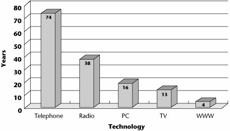
Figure 8.1 is an astounding graph that speaks to the pace of Internet development. It shows the number of years it took several technologies to reach 50 million users worldwide. As you can see, whereas it took 74 years for the telephone to reach 50 million users, it took the World Wide Web only 4.
Figure 8.1. Internet pace: Years to reach 50 million users worldwide
A number of forces are propelling our interest in the Internet. One main force is that usage continues to grow at an impressive rate. Today, more than 1 billion people actively use the Internet, although there are vast differences in the penetration and usage rates around the world. Recent statistics provided by Internet World Stats (www.internetworldstats.com) show that the greatest penetration (i.e., the percentage of the population with access to the Internet) is in North America, with 68.1% of the population online, followed by Oceania/Australia at 52.9%, and Europe at 35.9%. After these regions, the penetration drops off dramatically, with Latin America/the Caribbean at 14.3%, Asia at 9.9%, the Middle East at 9.6%, and Africa at 2.5%. However, the picture isn't complete without also looking at the actual usage rates (i.e., usage as a percentage of world traffic). Here Asia leads with 35.7%, followed by Europe with 28.5%, North America with 22.2%, Latin America/the Caribbean at 7.8%, Africa with 2.2%, and the Middle East and Oceania/Australia with 1.8% each.
Statistics also show that usage growth continues to be strong. For the period from 2000 to 2005, the percentage of growth was 454.2% in the Middle East, 403.7% in Africa, 337.4% in Latin America/the Caribbean, 218.7% in Asia, 176.1% in Europe, 132.2% in Oceania/Australia, and 108.9% in North America, with a global average of 182%. In general, the rate of Internet backbone growth has varied dramatically by region. Mature Internet markets in the United States and Europe have seen relatively slow growth, just 30% to 40% in 2005. Asian network backbones have grown much more rapidlyover 70% in 2005and show no signs of slowing. (Although it is indeed very useful to have a reference to such statistics, remember that there can be a wide variety of research results, and any such statistics are not cast in stone; rather, they should be considered as a simple guide to general usage trends.)
The Internet is very useful and easy to use, and for a growing number of people, it is now the first place to look for information. Electronic commerce (e-commerce) is also increasing, in both the business-to-consumer and business-to-business sectors. Another contributor is the major shift toward the use of advanced applications, including pervasive computing, which introduces a wide range of intelligent appliances ready to communicate through the Internet, as well as applications that include the more captivating visual and sensory streams; the entertainment industry in particular expects large growth in this space. Finally, the availability of broadband or high-speed access technologies further drives our interest in and ability to interact with Web sites that use these advanced applications and offer e-commerce capabilities.
A Brief History of the Internet
To help understand the factors that contributed to the creation of the Internet, let's look very briefly at the history of the Internet. The ancestor of the global Internet was the Advanced Research Projects Agency Network (ARPANET), developed by the U.S. Department of Defense Advanced Research Projects Agency (ARPA). Introduced in 1969, ARPANET was the world's first operational packet-switched network. There were several reasons for the development of ARPANET. First, the project was launched during the Cold War era, when the government wanted to build a network that had no single point of failure and that could sustain an attack and continue to function. As my colleague, Steve Riley of Microsoft, expresses, "The launch of Sputnik really galvanized the U.S. government into action. Before then, we were somewhat complacent, not really looking toward much future technological development."
For More InformationThe Internet Society offers "A Brief History of the Internet," written by the "fathers" of the Internet, at www.isoc.org/internet/history/brief.shtml. |
Second, there was great interest in creating a computer communications network that would enable ARPA-sponsored researchers, scattered around the nation, to use various ARPA computers, making research results and new software quickly and widely available to all concerned parties. The initial thought, in 1966, was to simply connect the large time-sharing mainframe computers to each other via telephone lines. However, some participants felt that having telephone lines terminating directly on their computers would create unwanted loads. Another idea then surfaced, calling for small independent computers to manage the communications links, and to then connect to the large time-sharing machines. This approach allowed the task of running the network to be offloaded from the ARPANET computers, while also allowing ARPA to have complete control over the network. These smaller computers came to be called interface message processors (IMPs). The initial ARPANET consisted of four IMPs, installed at four universities: University of California, Los Angeles; the Stanford Research Institute's Augmentation Research Center; the University of California, Santa Barbara; and the University of Utah's Graphics Department. The first ARPANET link was established on October 29, 1969, between the IMP at UCLA and the IMP at Stanford, and the entire four-node network was connected by December 5, 1969.
Toward the mid-1970s, ARPA was renamed the Defense Advanced Research Projects Agency (DARPA), and while it was working on the distributed, or packet-switched, network, it was also working on local area networks (LANs), paging networks, and satellite networks. DARPA recognized the need for some form of internetworking protocol that would allow open communications between disparate networks. Internet Protocol (IP) was created to support an open-architecture network that could link multiple disparate networks via gatewayswhat we today refer to as routers.
Jonathan Postel and the InternetJonathan Postel played a pivotal role in creating and administering the Internet. He was one of a small group of computer scientists who created the ARPANET, the precursor to the Internet. For more than 30 years he served as editor of the Request for Comments (RFC) series of technical notes that began with the earliest days of the ARPANET and continued into the Internet. Although intended to be informal, RFCs have often laid the foundation for technical standards governing the Internet's operation. Also for 30 years, Postel handled the administrative end of Internet addresses, under the auspices of the Internet Assigned Numbers Authority (IANA), a U.S. governmentfinanced entity. As part of the effort to hand over administration of the Internet to an international private corporation, Postel delivered a proposal to the U.S. government for transforming IANA into a nonprofit corporation with broad representation from the commercial and academic sectors. That organization is today known as the Internet Corporation for Assigned Names and Numbers (ICANN), which still manages IANA. |
In 1980, Transmission Control Protocol/Internet Protocol (TCP/IP) began to be implemented on an experimental basis, and by 1983, it was required in order for a subnetwork to participate in the larger virtual Internet.
The original Internet model was not based on the telephone network model. It involved distributed control rather than centralized control, and it relied on cooperation among its users, which initially were largely academicians and researchers. The original Internet had no regulation, no monopoly, and no universal-service mandate, although these issues are being considered seriously now.
Regulation of the InternetThe lack of regulation and mandates in the original Internet brings up myriad interesting questions: Did that lack actually accelerate the growth of the Internet? Did it also mean that Internet access is largely divided across economic ability? Why are people now considering adding regulation and universal-service mandates to the Internet? What problems will this solve? What problems will it exacerbate? Is it a good idea? Will such regulation fundamentally change the Internet from what it is today into something else? Although there are no concrete answers to these questions at the moment, it is a wonderful topic of discussion. A very good resource for many papers and studies on regulatory issues is the Cato Institute, at www.cato.org/tech, which can serve as a starting point in studying the impacts of regulation. |
Today, no one agency is in charge of the Internet, although the Internet Society (ISOC; www.isoc.org) is a nonprofit, nongovernmental, international organization for Internet professionals that focuses on Internet standards, education, and policy issues. ISOC serves as the organizational home of the Internet Engineering Task Force (IETF; www.ietf.org), which oversees various organizational and coordinating tasks. The IETF is an international community of network designers, operators, vendors, and researchers whose job is to evolve the Internet and smooth its operation by creating technical standards through consensus. In addition to the IETF, ISOC is composed of a board of trustees, the Internet Architecture Board (IAB; www.iab.org), the Internet Research Task Force (IRTF; www.irtf.org), the Internet Engineering Steering Group (IESG; www.ietf.org), and the Internet Research Steering Group (IRSG; www.irsg.org).
Another organization that is critical to the functioning and management of the Internet is the Internet Assigned Numbers Authority (IANA; www.iana.org), which is currently operated by the Internet Corporation for Assigned Names and Numbers (ICANN; www.icann.org) under a contract with the U.S. Department of Commerce, which also provides ongoing oversight. IANA oversees IP address allocation, the Domain Name System (DNS), root zone management, and other numerical assignments, such as protocol and port numbers. (DNS, top-level domains, and root servers are all discussed later in this chapter.) In its role of administering the data in the root name servers (at the top of the DNS hierarchy), IANA works closely with top-level domain (TLD) and root name server operators, as well as those involved with policy decisions at ICANN.
The registration of IP addresses around the world is delegated to five regional Internet registries (RIRs), which as a group are called the Number Resource Organization (NRO; www.nro.net):
- American Registry for Internet Numbers (ARIN; www.arin.net) for North America
- Asia Pacific Network Information Centre (APNIC; www.apnic.org) for the Asia-Pacific region
- Reseaux IP European Network Coordination Center (RIPE NCC; www.ripe.net) for Europe, Central Asia, and the Middle East
- Latin American and Caribbean Internet Addresses Registry (LACNIC; www.lacnic.net/en) for Latin America and the Caribbean
- African Network Information Centre (AfriNIC; www.afrinic.net) for Africa
Each RIR is responsible for overseeing the allocation and registration of Internet number resources within its region of the world. The resources the RIRs manage include both IPv4 and IPv6 addresses and autonomous system numbers. (Autonomous systems are discussed later in this chapter.) IANA delegates large groups of IPv4 addresses to the various RIRs, which then reallocate smaller groups of addresses in their regions to ISPs and other organizations. A process has also been established for the allocation of IPv6 addresses, although at this time there is little pressure in this area as the supply of IPv6 addresses greatly exceeds the demand. The NRO has entered into an agreement with ICANN to establish an organization, referred to as the Address Supporting Organization (ASO; www.aso.icann.org) to deal with the coordination of global IP addressing policies within the ICANN framework.
Since the formation of ICANN, the relationship between ICANN, the country code TLDs (ccTLDs), and the RIRs has been politically charged. As a result, a number of proposals have suggested the complete separation of the IANA function from ICANN, but at the same time, it has been deemed unwise to make any major changes to the control structure of the Internet as that could possibly risk "breaking" the Internet.
The section "Political and Regulatory Forces in Telecommunications" in Chapter 1, "Telecommunications Technology Fundamentals," provides more information on Internet regulation.
What the Internet Is and How It Works
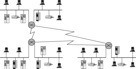
To understand the Internet, it is important to first understand the concept of a computer network (see Figure 8.2). A network is formed by interconnecting computers, typically referred to as hosts, in such a way that they can communicate. Connecting hosts involves two major components: hardware (i.e., the physical connections) and software. The software can be run on the same or dissimilar host operating systems, and it is based on standards that define its operation. These standards, referred to as protocols, provide the formats for passing packets of data, specify the details of the packet formats, and describe how to handle error conditions. The protocols hide the details of network hardware and permit computers of different hardware types, connected by different physical connections, to communicate despite their differences. (Protocols are discussed in detail later in this chapter.)
Figure 8.2. Network components
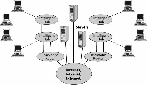
In the strictest sense, the Internet is an internetwork composed of a worldwide collection of networks, routers, gateways, servers, and clients linked by a common set of telecommunications protocolsthe IP family (see Figure 8.3). The term client is often used to refer to a computer on a network that takes advantage of the services offered by a server. It also refers to a user running the client side of a client/server application. The term server describes either a computer or a software-based process that provides services to network users or Web services to Internet users.
Figure 8.3. An internetwork
Networks connect servers and clients, allowing them to share information and computing resources. Network equipment includes cable and wire, network adapters, hubs, switches, and various other physical connectors. In order for a network to be connected to the Internet, the network must send and retrieve data by using TCP/IP and related protocols. Networks can also be connected to form their own internets: Site-to-site connections are known as intranets, internal networks that are generally composed of LANs interconnected by a wide area network (WAN) that uses IP; and connections between partnering organizations, using IP, are known as extranets.
The Internet is a complex, highly redundant collection of more than 10,000 interconnected autonomous systems, composed of telecommunications circuits connected with internetworking equipment, including routers, bridges, and switches. The level of redundancy varies, depending on how the autonomous systems are connected. In an environment consisting of several network segments with different protocols and architectures, the network needs a device that not only knows the address of each segment but also can determine the best path for sending data and filtering broadcast traffic to the local segment. The Internet moves data by relaying traffic in packets from one computer network to another. If a particular network or computer (i.e., router) is down or busy, the network is smart enough to reroute the traffic automatically. Routers make decisions about how to route the data or packets, they decide which path is best, and then they use that best path. Routers work at the network layer, Layer 3, of the OSI model, which allows them to switch and route packets across multiple networks. Routers build comprehensive sets of best routes to all locations that they know about. These routing tables can be quite large for complex networks. Routers can share status and routing information with one another and use that information to bypass slow or malfunctioning connections.
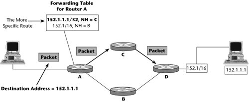
Routing is the main process that an Internet host uses to deliver packets. As shown in Figure 8.4, the Internet uses a hop-by-hop routing model, which means that each host or router that handles a packet examines the destination address in the packet's IP header, computes the next hop that will bring the packet one step closer to its destination, and delivers that packet to the next hop, where the process is repeated. To make this happen, routing tables must match destination addresses with next hops, and routing protocols must determine the content of these tables. The next hop is determined from looking up the next hop in the routing table, and routers must build and maintain these tables containing the "best routes." This routing is most often dynamic, scalable, and robust (assuming that the network is designed correctly).
Figure 8.4. Basic IP routing
The Internet and the public switched telephone network (PSTN) operate quite differently from one another:
- The Internet uses packet switching, where there's no dedicated connection and the data is fragmented into packets. Packets can be delivered via different routes over the Internet and reassembled at the ultimate destination. Historically, back-office functions such as billing and network management have not been associated with the Internet, although today these mechanisms are in place. But, in general, the Internet emphasizes flexibilitythe capability to route packets around congested or failed points.
- As discussed in Chapter 4, "The PSTN," the PSTN uses circuit switching, so a dedicated circuit is set up and taken down for each call. This allows charging based on minutes and circuits used, which, in turn, allows chain-of-supply dealings. The major emphasis of the PSTN is on reliability.
Although the Internet and the PSTN have different models and different ways of managing or routing traffic through the network, they share the same physical foundation in terms of the transport infrastructure, or the types of communication links they use. (Chapter 3, "Establishing Communications Channels," discusses packet switching and circuit switching in detail.)
Internet Protocols
The Internet is a collection of networks that are interconnected logically as a single large, virtual network. Messages between computers are exchanged by using packet switching. Networks can communicate with one another because they all use an internetworking protocol. Protocols are formal descriptions of messages to be exchanged and of rules to be followed in order for two or more systems to exchange information in a manner that the parties will understand.
The following sections examine the Internet's protocols: IP (Internet Protocol), TCP (Transmission Control Protocol), User Datagram Protocol (UDP), Stream Control Transmission Protocol (SCTP) and Datagram Congestion Control Protocol (DCCP), Internet Control Message Protocol (ICMP), Internet Group Management Protocol (IGMP), Address Resolution Protocol (ARP) and Reverse Address Resolution Protocol (RARP), routing protocols, and network access protocols. This collection of protocols is often referred to as the TCP/IP suite, although it contains much more than just TCP and IP. The IETF has technical responsibility for the suite, which is the most popular and widely used of the internetworking protocols. The nonproprietary nature of the suite is a major advantage, permitting the connection of hardware and operating systems of many different computers.
IP
IP handles packet forwarding and transporting of datagrams across a network. With packet forwarding, computers can send a packet on to the next appropriate network component, based on the address in the packet's header. IP defines the basic unit of data transfer, the datagram, also referred to as the packet, and it also defines the exact format of all data as it travels across the Internet. IP works like an envelope in the postal service, directing information to its proper destination. With this arrangement, every computer on the Internet has a unique address. (Addressing is discussed later in this chapter.)
Figure 8.5 shows the various components of a datagram. The entire datagram has four entitiesthe Payload field, the next protocol field (usually TCP or UDP), the IP field, and the L2 (Layer 2) fieldwhich, combined, are referred to as the Layer 2 packet (or protocol) data unit (PDU), or frame. Datagram, or packet, refers to the combination of the payload, the TCP/UDP information, and the IP address. Finally, the TCP maximum segment size (MSS) refers to the size of the payload and the next protocol header.
Figure 8.5. Datagram structure
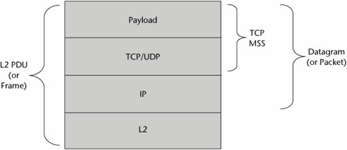
IP provides software routines to route and to store and forward data among hosts on the network. IP functions at Layer 3 (the network layer), and it provides several services, including host addressing, error notification, fragmentation and reassembly, routing, and packet timeout. The Layer 4 protocol, usually TCP or UDP, presents the data to IP in order to provide basic host-to-host communication. IP then attaches to the packet, in a protocol header, the address from which the data comes and the address of the system to which it is going.
Under the standards, IP allows a packet size of up to 64,000 bytes, but we don't transmit packets that large because they would cause session timeouts and big congestion problems. Therefore, IP packets are currently segmented into 1,500-byte-maximum chunksbecause this is what can fit inside a typical 1,536-byte Ethernet frame and because it is a pretty efficient size, helping to keep retransmission times down. This size is likely to increase, however, to improve performance over high-speed links.
Packets between a particular source and destination might not always travel the same route. IP does its best to make the delivery to the requested destination host along the best route currently available, but if it fails for any reason, it just drops the packet. Upper-level protocols should therefore not depend on IP to deliver the packet every time. Because IP provides connectionless, best-effort service and because packets can get lost or arrive out of sequence, TCP provides a way to recover from these problems.
TCP
Many network applications present data to TCP, the most common Layer 4 (transport layer) protocol. TCP divides the data into packets and gives each packet a sequence number that is not unique but is nonrepeating for a very long time. These packets could represent text, graphics, sound, or videoanything digital that the network can transmit. The sequence numbers help to ensure that the packets can be reassembled correctly and in the proper order at the receiving end. Thus, each packet consists of content, or data, as well as the protocol header, the information that the protocol needs to do its work.
TCP uses another piece of information to ensure that the data reaches the right application when it arrives at a systemthe port number, which is within the range 1 to 65,535. In an IP network, it is a number assigned to user sessions and server applications. The port number resides in the TCP header as well as in the UDP header for applications such as VoIP and videoconferencing. The source port, which can be a random number, is assigned to the client and is used to keep track of user sessions. The combination of port number and IP address is called a socket. The destination port is used to route packets on a server to the appropriate network application. On servers, port numbers identify running applications that are waiting for incoming connections from clients. Port numbers distinguish one listening application from another. Numbers between 1 and 1,023 are reserved for well-known server applications (e.g., Web servers run on port 80, FTP runs on port 21). Also, many recent protocols have been assigned well-known port numbers above 1,023. Ports with higher numbers, called ephemeral ports, are dynamically assigned to client applications as needed. A client obtains a random ephemeral port when it opens a connection to a well-known server port. Firewalls can use port numbers and IP addresses to control the flow of information. (Firewalls are discussed in Chapter 9, "IP Services.")
TCP is the protocol for sequenced and reliable data transfer. It breaks the data into pieces and numbers each piece so that the receipt can be verified and the data can be put back in the proper order. TCP provides Layer 4 functionality, and it is responsible for virtual circuit setup, acknowledgments, flow control, and retransmission of lost or damaged data. TCP provides end-to-end, connection-oriented, reliable, virtual circuit service.
UDP
Like TCP, UDP is a Layer 4 (transport layer) protocol that operates over IP. UDP provides end-to-end, connectionless, unreliable datagram service. It is well suited for query/response applications, for multicasting, and for use with Voice over IP (VoIP). (VoIP is discussed in Chapter 9.) Because UDP does not request retransmissions, it minimizes what would otherwise be unmanageable delay; the result is that sometimes the quality is not very good. For instance, if you encounter losses or errors associated with a voice packet, the delays that would be associated with retransmitting that packet would render the conversation unintelligible. In VoIP, when you lose packets, you do not request retransmissions. Instead, you hope that the user can recover from the losses by other means. Unlike TCP, UDP does not provide for error correction and sequenced packet delivery; it is up to the application itself to incorporate error correction, if required.
So why use UDP? Multimedia applications typically can't tolerate the additional time required for establishing TCP's virtual connection and the overhead used by TCP's delivery guarantee mechanisms. You can think of UDP as an open "pipe" between two computers that simply allows for an uninterrupted flow of data. The experience of watching a movie over the Internet under UDP is much better; you won't miss the occasional dropped datagram. Over highly controlled and error-correcting TCP, the sequencing overhead most likely would result in greater congestion and more dropped packets.
SCTP and DCCP
SCTP is a new Layer 4 (transport layer) protocol designed to overcome the limitations of TCP with respect to transport of signaling messages and VoIP networks. SCTP was originally intended for the transport of telephony signaling protocols (such as SS7) over IP, with the goal of duplicating some of the reliability characteristics of SS7 in IP. Other applications may benefit as well, such as multimedia Web browsing, video over IP, and IPTV. SCTP provides many of the features of TCP, and it also includes multistreaming, which supports independent transport and delivery of multiple streams between two communicating hosts. It can apply per-stream, in-order delivery to the destination application. It also includes multihoming, which supports more than one path between hosts for resilience. Multihoming exchanges more than one usable IP address during association setup but can use only one at a time.
DCCP is another new Layer 4 protocol that provides congestion control for unreliable data flows. Its features include unreliable transport with acknowledgments (DCCP never retransmits data), reliable handshake and negotiation of features, and support for TCP-like or TCP-friendly rate control for congestion control.
SCTP and DCCP are designed to address the growing range of voice, video, and multimedia applications being introduced on the Internet and IP networks and will provide for improved performance, but so far they have seen little deployment.
ICMP
ICMP provides error-handling and control functions. It is tightly integrated with IP. ICMP messages, delivered in IP packets, are used for control messages related to network operation or misoperation. Because ICMP uses IP, ICMP packet delivery is best-effort delivery. ICMP functions include announcing network errors, network congestion, and timeouts, as well as assisting in troubleshooting.
IGMP
IGMP is a Layer 3 (network layer) protocol whose primary purpose is to allow Internet hosts to participate in multicasting. The IGMP standard describes the basics of multicasting IP traffic, including the format of multicast IP addresses, multicast Ethernet encapsulation, and the concept of a host group (i.e., a set of hosts interested in traffic for a particular multicast address). IGMP enables a router to determine which host groups have members on a given network segment, but IGMP does not address the exchange of multicast packets between routers.
ARP and RARP
Layer 3 (the network layer) is home to the protocols ARP and RARP. ARP determines the physical address of a node, given that node's IP address. ARP is the mapping link between IP addresses and the underlying physical address, known as the Media Access Control (MAC) address. RARP enables a host to discover its own IP address by broadcasting its physical address. When the broadcast occurs, another node on the LAN answers with the IP address of the requesting node.
Routing Protocols
Routing protocols are protocols that allow routers to communicate with each other. They include Routing Information Protocol (RIP), interior gateway protocols (IGPs) such as Open Shortest Path First (OSPF), Exterior Gateway Protocol (EGP), and Border Gateway Protocol (BGP).
Several processes are involved in router operation. First, the router creates a routing table to gather information from other routers about the optimum paths. As discussed in Chapter 6, "Local Area Networking," routing tables can be static or dynamic; dynamic routing tables are best because they adapt to changing network conditions. Next, when data is sent from a network host to a router, on the way to its destination, the router examines the destination address in the IP header to determine the most efficient path to the destination. Routing protocols consider various metrics, including distance and cost, when computing the best path.
The following sections discuss the various routing protocols, including distance-vector and link-state protocols, interior routing protocols, and exterior routing protocols.
Distance-Vector Versus Link-State Protocols
Two main types of routing protocols are involved in making routing decisions: distance-vector and link-state routing protocols.
Distance-vector routing protocols require that each router simply inform its neighbors of its routing table. Routers periodically flood a table of vectors. (A vector is destination, distance, interface, and next hop.) Other routers receive the table, add their local costs, and calculate the forwarding table. For each network path, the receiving router picks the neighbor advertising the lowest cost, and then the router adds that into its routing table for readvertisement. Common distance-vector routing protocols are RIP (implementations of which exist both for IP and for Novell's Internetwork Packet Exchange [IPX]), AppleTalk Routing Table Maintenance Protocol (RTMP), and Cisco's Interior Gateway Routing Protocol (IGRP).
Link-state routing protocols control the routing process and enable routers to respond quickly to changes in the network. Link-state routing determines path lengths by using algorithms that incorporate numbers of hops, line speeds, amounts of traffic, and costs. With link-state routing, every node (router) receives a map, in the form of a graph, showing the connectivity of the network (i.e., which nodes are connected to which other nodes). Each node independently calculates the best next hop from itself to every possible node in the network. In this way, the routing table for each node is the collection of best next hops for that node.
Unlike distance-vector routing, where each node shares its routing table with its neighbors, in link-state routing, the only information exchanged between the nodes is the information used to construct the connectivity maps. Link-state routing is more reliable, easier to debug, and less bandwidth intensive than distance-vector routing, but it is also more complex and more computer and memory intensive. Link-state algorithms are more efficient and create less network traffic than do distance-vector algorithms; this can be crucial in environments that involve multiple WAN links. OSPF, Intermediate System to Intermediate System (IS-IS), and NetWare Link Services Protocol (NLSP) are link-state routing protocols.
Interior Routing Protocols
Interior routing occurs within an autonomous system, which is a collection of routers under a single administrative authority that uses a common IGP for routing packets. Most of the common routing protocols, such as RIP, OSPF, and IS-IS, are interior routing protocols.
The autonomous system number is a unique number that essentially identifies a portion of the Internetusually owned or administered by a particular organization. Autonomous system numbers are managed and assigned by the RIRs (i.e., ARIN, APNIC, RIPE NCC, LACNIC, and AfriNIC). Exterior routing protocols, such as BGP, use autonomous system numbers to uniquely define borders between various networks in the Internet. The basic routable element, the item on which the routing decision is based, is the IP network or subnetwork, or the Classless Interdomain Routing (CIDR) prefix for newer protocols. (CIDR is discussed later in this chapter.)
OSPF
OSPF, which is sanctioned by the IETF and supported by TCP, is perhaps the most widely used interior routing protocol in large networks. OSPF is a link-state protocol that has a complex set of options and features. It makes use of Dijkstra's algorithm, which determines routes based on path length, calculates the shortest-path tree, and uses cost as its routing metric.
An OSPF network is divided into areas, or logical groupings of routers whose information can be summarized and sent toward the rest of the network. The core of the network is formed by a special area called the backbone area, and all interarea routing occurs via this backbone. All areas must connect to the backbone, and if no direct connection is possible, a virtual link may be established. The other areas, which vary in their ability to receive external and/or summary route information, are as follows:
- Stub area (SA) The SA does not receive any external routes and needs to rely on a default route to send traffic to routes outside the immediate domain. (A default route is the network route used by a router or server when no other known route works for a given IP packet's destination address.) Hosts and routers in an organization generally point the default route toward the router that has a connection to a network service provider to ensure that packets destined for the Internet will be sent toward the router that has the Internet connection.
- Totally stubby area (TSA) The TSA does not receive any external routes or summary routes. The only way for traffic to get routed outside the area is by using a default route that is the only link advertised into the area.
- Not-so-stubby area (NSSA) The NSSA can import autonomous system external routes and send them to the backbone but cannot receive autonomous system external routes from the backbone or other areas.
OSPF defines various router types, which are also logical definitions, and a router may be classified as more than one type. The main types of routers are as follows:
- Area border router (ABR) The ABR is a router that connects one or more OSPF areas to the backbone network.
- Autonomous system boundary router (ASBR) The ASBR is a router that is connected to more than one autonomous system and exchanges information with routers in other autonomous systems. It is used to distribute routing information from other autonomous systems throughout its own autonomous system.
- Internal router (IR) An IR is a router that exchanges routing information only with routers in the same area.
- Backbone router (BR) The BR has a connection into the backbone area.
- Designated router (DR) The DR is a router elected by the network based on calculating the router's priority number and router ID.
The basic building block of the OSPF routing protocol for IP is the link-state advertisement (LSA). The LSA provides a description of a router's local routing topology that the router advertises (distributes) to all other routers. Because OSPF is designed with scalability in mind, not all LSAs are flooded (i.e., advertised) on all the interfaces; instead, they are sent only to the interfaces that belong to the appropriate area. This allows the detailed information to be kept local, while summary information is provided to the rest of the network. There are 11 LSAs defined in OSPF, each applicable to a particular area and type of router.
Routers that belong to the same broadcast domain (i.e., that belong to the same network) form what are called adjacencies, or the relationship of being neighbors. The routers elect a DR, which acts as a hub to reduce traffic between routers. OSPF makes use of both unicast and multicast (discussed later in this chapter) to send "hello" packets and link-state updates.
In keeping with advances in Internet protocols, a number of updates have been added to OSPF, including OSPFv3 (version 3), which allows support for IPv6. Another update introduces Nonstop Forwarding (also referred to as Hitless Run and Graceful Restart), which means that in the event of a network disruption, routers keep forwarding packets as the OSPF process is restarted. Two more working areas are the ability to support multiple address families (IPv4 and IPv6) as well as OSPF extensions accommodating Traffic Engineering DiffServ (a statistical technique used to predict and engineer the behavior or the network) and optical technologies.
IS-IS
IS-IS is another protocol that routers can use to determine the best way to forward packets through the network (i.e., to perform routing). It is also an IGP, which means it is used within an administrative domain or network, not between networks. (Routing between administrative domains or networks is the job of BGP.) Like OSPF, IS-IS is also a link-state routing protocol and uses Dijkstra's algorithm.
One difference between IS-IS and OSPF is that IS-IS does not use IP to carry the routing information messages. They also differ in the way they define areas and routers. In IS-IS, routers are designated as being Level 1 (intra-area), Level 2 (interarea), or Level 12 (both). Level 1 routers exchange information only with other Level 1 routers, Level 2 routers exchange information only with other Level 2 routers, and Level 12 routers exchange information with both levels and are used to connect the interarea routers with the intra-area routers. OSPF networks look somewhat like a star topology, or spider web, of many areas all attached to the backbone area. IS-IS looks more like a central spine of Level 2 routers with branches of Level 12 and Level 1 routers forming the individual areas or networks.
IS-IS was developed by the telecommunication group of the International Telecommunication Union (ITU-T; www.itu.int/ITU-T) around the same time that the IETF was developing OSPF. As discussed previously, OSPF is the dominant IGP routing protocol today, although IS-IS has become more widely used as a viable alternative to OSPF in the enterprise in recent years. As with OSPF, updates continue to be made to IS-IS, including revisions that support IPv6 (IS-IS for IPv6) and Restart Signaling (another name for OSPF's Nonstop Forwarding). The Multitopology (MT) routing extension to IS-IS allows for routing between a set of independent IP topologies; it can be used for a variety of purposes, such as maintaining separate IGP routing domains for isolated multicast or IPv6 islands within the backbone, forcing a subset of an address space to follow a different topology, or adding an in-band management network on top of the original IGP topology. As with OSPF, IS-IS also has extensions that accommodate Traffic Engineering DiffServ and optical technologies.
Exterior Routing Protocols
Exterior routing occurs between autonomous systems and is of concern to service providers and other large or complex networks. As shown in Figure 8.6, gateway protocols are used within and between autonomous systems. Whereas there may be many different interior routing schemes, a single exterior routing scheme manages the global Internet, and it is based on the exterior routing protocol BGP version 4 (BGP4). The basic routable element is the autonomous system. Routers determine the path for a data packet by calculating the number of hops between internetwork segments. Routers build routing tables and use these tables along with routing algorithms.
Figure 8.6. The role of gateway protocols
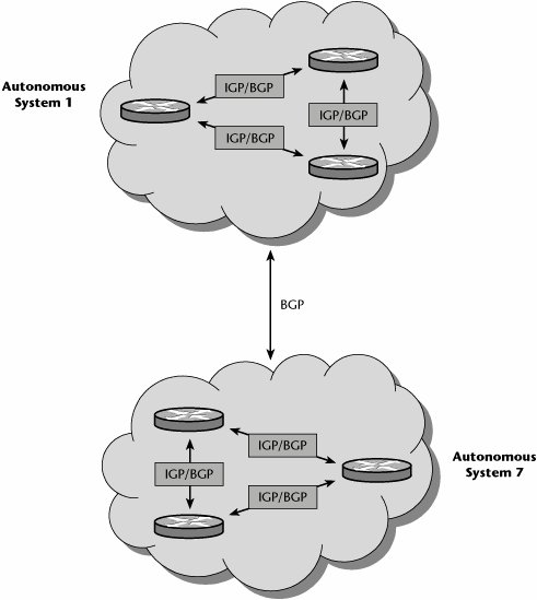
BGP, the core routing protocol of the Internet, works by maintaining a table of IP networks, or prefixes, that designate network reachability between autonomous systems. BGP makes use of a path-vector protocol, which means routing decisions are based on network policies or rules rather than on technical parameters, as is the case with distance-vector and link-state protocols. In BGP, the routing table maintains the autonomous systems that are crossed in order to reach the destination system. Very large private IP networks can also use BGP.
Although most Internet users do not use BGP directly, most ISPs must use BGP to enable routing with each other, and it is considered one of the most important protocols of the Internet. BGP is as important to the Internet as SS7 is to interprovider core call setup on the PSTN (which is discussed in Chapter 4).
Like OSPF and IS-IS, BGP is also being updated with new extensions. Current working areas include Multiprotocol BGP, which includes support for IPv6, virtual private networks (VPNs), and multicast addresses. Another working area is Graceful Restart, in which data traffic continues to be routed between the restarting router and peers. BGP is also being updated to support Layer 2 VPN and Layer 3 VPN autodiscovery as well as Virtual Private LAN Services (VPLS) signaling. (VPNs and VPLS are discussed in detail in Chapter 9.)
Network Access Protocols
Network access protocols operate at Layer 2. They provide the underlying basis for the transport of IP datagrams. The original network access protocol was Ethernet, but IP can be transported transparently over any underlying network, including Token Ring, FDDI, Fibre Channel, wireless, X.25, ISDN, Frame Relay, or ATM.
Both Serial Line Internet Protocol (SLIP) and Point-to-Point Protocol (PPP) were designed specifically for IP over point-to-point connections. PPP provides data linklayer functionality for IP over dialup/dedicated links. In other words, whenever you dial in to your ISP, you negotiate a PPP session, and part of what PPP does is to provide a mechanism to identify and authenticate the user who is dialing up and provide an IP address to the remote computer.
Internet Network Architectures
Because two key characteristics of TCP/IP are vital to the Internet, it is appropriate to say that the Internet is the TCP protocol suite. First, TCP/IP is a layered structure (refer to Figure 5.9 in Chapter 5, "Data Communications Basics"). It gets more comprehensive in the layers above IP, and it has become extensive in the layers below IP; that is, numerous protocols are supported at the application layer (e.g., FTP and HTTP), and increasingly more options are available at the physical layer for connectivity. Second, IP decouples applications from the transmission or transport: IP does not care what the application is, and IP does not care what transport is used.
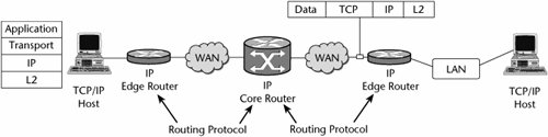
Figure 8.7 identifies the key elements in a TCP/IP network. The TCP/IP transmission consists of the application, transport, IP, and L2 layers. The hosts deal with the application and transport layers, and the network acts on the IP and L2 information. The network is composed of IP edge routers, IP core routers, and the transmission networks between them. The routers examine the IP field to determine the appropriate routing of the message, and the routing protocol determines the specific technique used to determine the proper route. The hosts examine the TCP fields to ensure guaranteed service, checking for any errors or lost packets and requesting retransmissions when errors occur, and they also work with the application data.
Figure 8.7. The key elements in a TCP/IP network
TCP/IP is the darling of the networking world for several important reasons:
- It provides a common internetworking paradigm IP enables internetworking (i.e., creating one big virtual network).
- It supports many IP routing protocols The two major routing protocols are BGP and IGP. BGP distributes external network addresses within and between autonomous systems (which are discussed in more detail earlier in this chapter). BGP4 is currently the interautonomous system routing protocol of choice. IGP distributes internal prefixes only inside autonomous systems or to border routers leading to external networks. Examples include OSPF, IS-IS, and RIP version 2 (RIPv2).
- It supports many transport protocols TCP/IP supports several main transport protocols, including TCP, UDP, DCCP, and SCTP. TCP is connection oriented, provides for flow and congestion control, and operates in a unicast mode. UDP is connectionless and therefore associated with unreliable transport. DCCP is one of the new transport protocols; it adds congestion control while still being associated with unreliable transport. SCTP is a new transport protocol that provides multistream and multihoming support.
- It supports many link layers TCP/IP is data link agnostic. IP can work over many link layers, including Ethernet, IP, PPP, MPLS, ATM, optical, and wireless options. Along with being an open standard, TCP/IP also offers support for a wide variety of implementation scenarios.
IP over Birds?For a taste of the humorous side of telecommunications and standards, you must take a look at the RFCs for "IP over avian carriers." These are classics. RFC 1149 (www.ietf.org/rfc/rfc1149.txt) was the original; it was updated by RFC 2549 (www.ietf.org/rfc/rfc2549.txt) to include quality of service. Someone actually tried implementing RFC 1149. Amazing! Read about it at www.blug.linux.no/rfc1149. And be sure to check out the log of the real ping session, at www.blug.linux.no/rfc1149/pinglogg.txt. |
Figure 8.8 illustrates the main aspects of an ISP's network architecture. The customers at the edge access the ISP's point of presence (POP) via an edge router that is part of the intra-POP fabric, the internal workings of the ISP's POP. (This information is covered in more detail later in this chapter, in the section "The Evolution of the POP Architecture.")
Figure 8.8. An ISP's network architecture
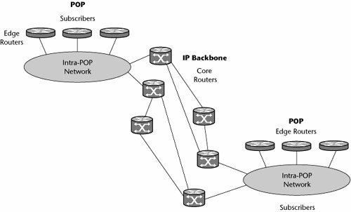
As you can see in Figure 8.8, the ISP backbone is composed of a series of core routers and the transmission links between them. Remember that the backbone may also contain ATM switches; a large percentage of ISP backbones include ATM technology because they need to provide business-grade services with guaranteed quality of service (QoS), and they need to perform the highest class of traffic engineering to ensure maximum network performance.
From here, various ISPs are connected to create the Internet (see Figure 8.9). There are various levels of ISPs. For example, backbone ISPs serve at the highest level of the hierarchy and provide connectivity between the tens of thousands of ISPs worldwide. Below them are several classes of ISPs, including those that may cover a large area and support both business customers and basic consumers as well as local ISPs that more commonly serve small communities and focus on rock-bottom prices for consumers rather than business-class services for enterprises.
Figure 8.9. Internet composition
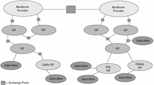
ISPs compete based on brand name, value-added services, performance, reliability, price, customer service, and other factors. Global Internet connectivity depends on private cooperation between ISPs. ISP cooperation, in turn, requires agreements about the business relationship, physical interconnection (called peering), ability to exchange routing information (e.g., via BGP), ability to exchange data, and the payment policy.
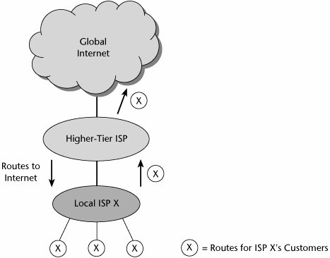
As Figure 8.10 shows, lower-level ISPs or local providers connect to higher-tier ISPs, which connect to the global Internet. ISPs exchange each other's customer routes and share the costs. Smaller ISPs pay a transit fee to larger ISPs for access to global routing tables.
Figure 8.10. ISP transit architecture
Internet Addressing and Address Resolution |
Part I: Communications Fundamentals
Telecommunications Technology Fundamentals
- Telecommunications Technology Fundamentals
- Transmission Lines
- Types of Network Connections
- The Electromagnetic Spectrum and Bandwidth
- Analog and Digital Transmission
- Multiplexing
- Political and Regulatory Forces in Telecommunications
Traditional Transmission Media
Establishing Communications Channels
- Establishing Communications Channels
- Establishing Connections: Networking Modes and Switching Modes
- The PSTN Versus the Internet
The PSTN
- The PSTN
- The PSTN Infrastructure
- The Transport Network Infrastructure
- Signaling Systems
- Intelligent Networks
- SS7 and Next-Generation Networks
Part II: Data Networking and the Internet
Data Communications Basics
- Data Communications Basics
- The Evolution of Data Communications
- Data Flow
- The OSI Reference Model and the TCP/IP Reference Model
Local Area Networking
Wide Area Networking
The Internet and IP Infrastructures
- The Internet and IP Infrastructures
- Internet Basics
- Internet Addressing and Address Resolution
- The Organization of the Internet
- IP QoS
- Whats Next on the Internet
Part III: The New Generation of Networks
IP Services
Next-Generation Networks
- Next-Generation Networks
- The Broadband Evolution
- Multimedia Networking Requirements
- The Broadband Infrastructure
- Next-Generation Networks and Convergence
- The Next-Generation Network Infrastructure
Optical Networking
- Optical Networking
- Optical Networking Today and Tomorrow
- End-to-End Optical Networking
- The Optical Edge
- The Optical Core: Overlay Versus Peer-to-Peer Networking Models
- The IP+Optical Control Plane
- The Migration to Optical Networking
Broadband Access Alternatives
- Broadband Access Alternatives
- Drivers of Broadband Access
- DSL Technology
- Cable TV Networks
- Fiber Solutions
- Wireless Broadband
- Broadband PLT
- HANs
Part IV: Wireless Communications
Wireless Communications Basics
- Wireless Communications Basics
- A Brief History of Wireless Telecommunications
- Wireless Communications Regulations Issues
- Wireless Impairments
- Antennas
- Wireless Bandwidth
- Wireless Signal Modulation
- Spectrum Utilization
Wireless WANs
- Wireless WANs
- 1G: Analog Transmission
- 2G: Digital Cellular Radio
- 5G: Enhanced Data Services
- 3G: Moving Toward Broadband Wireless
- Beyond 3G
- 4G: Wireless Broadband
- 5G: Intelligent Technologies
WMANs, WLANs, and WPANs
Emerging Wireless Applications
- Emerging Wireless Applications
- The Handset Revolution
- Mobile IP
- The IP Multimedia Subsystem
- Mobile Gaming
- Mobile Video
- Mobile TV
- Mobile Content
Glossary
EAN: 2147483647
Pages: 160
