VPNs
VPNs are a crucial requirement for businesses because they distribute mission-critical and sensitive traffic to remote locations. More and more often, customers are looking at mechanisms for securing traffic and for extending the reach of the enterprise to geographically dispersed locations. VPN technology is also being extended to the home office, providing telecommuters with networking security and performance comparable with that available at the office.
A big driver of interest in VPNs has been that customers need to communicate with people outside their enterprise, not just those inside the enterprise. As mentioned in Chapter 5, "Data Communications Basics," in the 1980s, about 80% of the information that was used within a given address of a business came from within that address. Only 20% was exchanged outside the walls of that location. Today, the relationship has reversed: As much as 80% of information exchanged is with points outside a given business address.
Another reason for interest in VPNs has been that customers want to quickly and securely change their access points as changes occur in their businesses. Many strategic alliances and partnerships require companies to exchange messages quickly. Some of these are temporary assignmentsfor example, a contractor building a fiber-optic loop or an applications developer building a new billing systemthat might last a few months, during which time the individuals involved need to be incorporated into the network. Leased lines are infamous for requiring long waits for provisioningoften 6 to 18 months. VPNs allow rapid provisioning of capacity where and when needed.
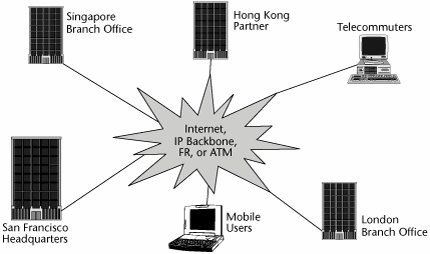
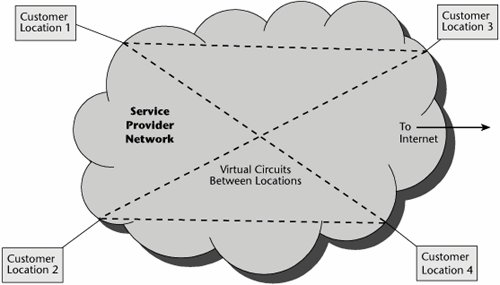
Traffic has steadily migrated away from traditional networks based on leased lines (see Figure 9.9) to public networks. As a result, we're seeing a steady growth in the pseudoprivate realm of the VPN (see Figure 9.10). A VPN is a logical network that isolates customer traffic on shared service provider facilities. In other words, the enterprise's traffic is aggregated with the traffic of other companies. VPNs have been around for quite some timesince X.25 closed user groups on the packet-switched network and the AT&T Software-Defined Network (SDN) on the circuit-switched networks. A VPN looks like a private network, but it runs across either the public circuit-switched network or public packet-switched data networks. Thus, a VPN is not just a solution within the IP realm; a VPN is a concept, not a specific set of technologies, and it can be deployed over a wide range of network technologies, including circuit-switched networks, X.25, IP, Frame Relay, ATM, and MPLS.
Figure 9.9. An enterprise network based on leased lines
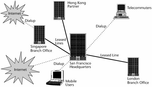
Figure 9.10. An enterprise network using a VPN
With the advances in VoIP and Video over IP, consumers have realized that they can converge real-time applications such as voice, video, and data into one access circuit. Carriers have realized that with the evolution of converged technologies, they no longer need to deploy, maintain, and support both TDM and IP backbones. However, carriers' IP backbones provide neither segmentation of customer traffic nor the security normally associated with that segmentation. Under the initiative of service providers, the standards organizations have recognized the value of starting work on the standardization of VPN technology, through ITU-T Study Group 13 and the IETF Provider Provisioned VPNs (PPVPNs) group. These standardization efforts have focused on the provider-provisioned class of VPNs. Today's provider-provisioned and provider-managed VPNs are intended to emulate whatever LAN or WAN connectivity a customer desires.
The following sections discuss key VPN concepts, types of VPNs, and VPN security.
Key VPN Concepts
A VPN uses a shared carrier infrastructure. It can provide additional bandwidth on demand, which is an incredible feat, compared to the weeks it normally takes to add bandwidth to dedicated networks. Carriers build VPNs with advanced survivability and restoration capabilities, as well as network management tools and support, so that QoS can be considered and service-level agreements (SLAs) can be administered and met.
There are two major models of VPNs:
- Customer edge model This customer-based model requires the CPE to be fully capable of configuring and provisioning the VPN and thereby results in higher operating expenses for the enterprise user. The routing intelligence resides at the end-user's site. Service providers install gateways, routers, and other VPN equipment on the customer's premises. Because this requires the service provider to manage onsite equipment, the cost associated with the onsite visits from field engineers can be high. This approach is generally preferred where the customer wants to have control over all aspects of security.
- Provider edge model In this model, the VPN intelligence resides at the provider's edge, where it can be extended out to many end-user locations. The carrier houses all the necessary equipment at a point of presence (POP) near the customer's location. This offers the advantages of scalability, support of an increasingly diverse range of IP-based services, and efficient prioritization of traffic. It provides the foundation needed to integrate fixed and mobile VPN communications into one seamless framework. This approach is generally preferred by customers who want to take advantage of the carrier's VPN economies of scale.
VPN Frameworks
Contemporary VPNs can be described as belonging to one of three categories: Internet-based VPNs, provisioned VPNs, and IP-based VPNs. The following sections define the nature of these types of VPNs.
Internet-Based VPNs
In an Internet-based VPN (see Figure 9.11), smaller ISPs provide local access services in defined geographical regions, requiring an enterprise to receive end-to-end services from multiple suppliers. An Internet-based VPN uses encryption to create a form of closed user group, thereby isolating the enterprise traffic and providing acceptable security for the enterprise across the public shared packet network. However, because it involves multiple ISPs in the delivery of the VPN, the performance is unpredictable. The biggest problem of having multiple suppliers is the inability to define and meet consistent end-to-end bandwidth or performance objectives.
Figure 9.11. An Internet-based VPN
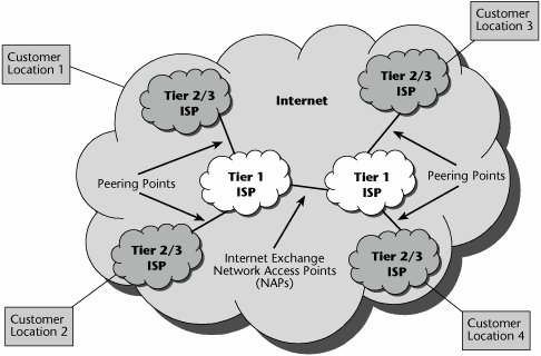
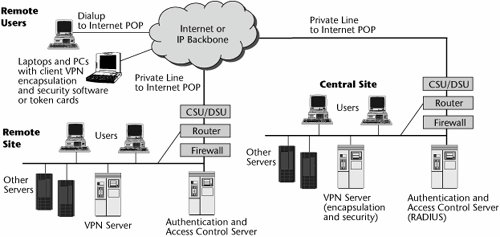
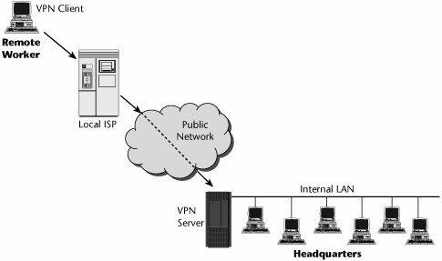
Figure 9.12 shows what is involved in providing an Internet-based VPN. The customer has on the premises a wide variety of servers that dish up the corporate content, the finance systems, the customer service systems, and so on. A VPN is responsible for the encapsulation of the information and hence the security aspects. Remote Authentication Dial-in User Services (RADIUS), an authentication and access control server, is used to authenticate a user who wishes to access corporate resources. The RADIUS server connects to a directory server, which contains the user accounts of those allowed to access the network. Traffic from the VPN server usually passes through a firewall, which determines whether traffic is allowed into or out of the network. The router selects the optimum path for the messages to take, and the circuit physically terminates on a channel service unit/data service unit (CSU/DSU). A private line interfaces with the Internet provider's POP. From that point, the VPN either uses the public Internet that comprises multiple ISPs or relies on IP backbones provided by an individual provider or at least a small group of providers. Users who are working on mobile devices have laptops equipped with the client and VPN services necessary for encapsulation and for administration of security.
Figure 9.12. The parts of an Internet-based VPN
Provisioned VPNs
VPNs rely on the capability to administer preferential treatment to applications, users, and so on. The public Internet does not support preferential treatment because it is subject to delay, jitter, and loss; it is therefore unsuitable for next-generation services that require high performance. In most cases, to accommodate business customers that are interested in such advanced services and that demand SLAs, the underlying transport is Frame Relay or ATM. Frame Relay and ATM VPNs offer greater levels of QoS and can fulfill the SLAs that customers and vendors agree to. However, they require that the customer acquire an integrated access device (IAD) to have on the premises, which can increase the deployment cost significantly. IADs enable the enterprise to aggregate voice, data, and video traffic at the customer edge.
A provisioned VPN (see Figure 9.13) is a packet-switched VPN that runs across the service provider's backbone, generally using Frame Relay or ATM. This type of VPN is built on OSI model Layer 2 virtual circuits, such as those used by Frame Relay, ATM, or MPLS, and it is provisioned based on customer orders. Virtual circuits based on predetermined locations create closed user groups and work well to carve out a VPN in a public shared network by limiting access and usage to the provisioned VPN community. However, encryption is still required to securely protect the information from theft or modification by intruders.
Figure 9.13. A provisioned VPN
A provisioned VPN is differentiated from an IP-based VPN by its ability to support multiple protocols and by the fact that it offers improved performance and management. These VPNs are characterized as having excellent performance and security, but the negative is that a single vendor may not offer the necessary reach and breadth in terms of service offerings.
Figure 9.14 shows what the CPE looks like for a VPN based on Frame Relay or ATM. The customer has an IAD that allows voice and data to be converged at the customer premises. The IAD feeds into the data communications equipment, over which a circuit goes to the service provider's POP. At the service provider's POP is a multiservice access device that enables multiple protocols and interfaces to be supported and that provides access to the service provider's core network, which is based on the use of Frame Relay or ATM. To differentiate Frame Relay and ATM-based VPNs from IP-based VPNs, service providers stress that multiple protocols are supported and that they rely on the use of virtual circuits or MPLS labels to facilitate the proper path, thereby ensuring better performance and providing traffic management capabilities.
Figure 9.14. A Frame Relay- or an ATM-based provisioned VPN
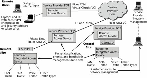
To further differentiate Frame Relay or ATM-based VPNs from regular Frame Relay or ATM services, additional functionssuch as packet classification and traffic isolation, the capability to handle multiple separate packet-forwarding tables and instances of routing protocols for each customerreside at the edge.
IP VPNs
Whereas Internet-based VPNs tend to involve numerous ISPs, IP-based VPNs tend to involve IP backbones that are under the control of a given service provider or a customer-owned enterprise network. An IP VPN is basically a private, or restricted, communications network constructed over shared IP-based networks, usually serviced on the providers' backbones, but with connections to the public Internet. IP-based VPNs have traditionally been referred to as networks of secure links over a public IP infrastructure. However, today an IP VPN is likely to be an MPLS-based infrastructure. (BGP MPLS VPNs are discussed later in this chapter.) However, as far as the user is concerned, the experience is the same, regardless of the technique. IP VPN services provide secure access for connecting intranets to other intranets, support mobile and teleworker access to their enterprise intranets, and provide for the connection of extranets to private enterprise, education, and government networks.
As discussed later in this chapter, there are two broad categories of IP VPNs:
- Network-based VPNs With a network-based VPN, all the routing intelligence and VPN topology for the VPN are provided on the carrier's provider edge. Network-based IP VPNs make life much easier for users: Because all of the VPN topology is stored on the carrier's provider edge, the provider has the responsibility of managing all the complexity of the VPN topology. All the customer needs is a single connection from the CPE to the provider edge.
- CPE-based VPNs In the case of CPE-based VPNs, which are most often based on IPsec, the network topology is defined at the customer's edge router. Obviously, with large or highly meshed networks, the management of so many tunnels and VPN rules can be overwhelming and can severely affect the capabilities of customers' edge routers.
IP VPNs are discussed in detail later in this chapter.
VPN Tunneling
The goal of a VPN is to provide connectivity over a shared infrastructure that is as secure and cost-effective as a dedicated private network such as a Frame Relay or ATM network. In addition, a VPN solution must be scalable, highly available, and easy to manage. And of course, QoS is a required feature. A VPN works by using the shared public infrastructure while maintaining privacy through security procedures and tunneling protocols, such as Point-to-Point Tunneling Protocol (PPTP), Layer 2 Tunneling Protocol (L2TP), Generic Routing Encapsulation (GRE), and IP Security (IPsec).
In effect, the protocols, by encrypting data at the sending end and decrypting it at the receiving end, send the data through a tunnel that cannot be entered by data that is not properly encrypted. An additional level of security involves encrypting not only the data but also the originating and receiving network addresses. Tunneling is the transmission of data intended for use only within a private, usually enterprise, network through a public network in such a way that the routing nodes in the public network are unaware that the transmission is part of a private network.
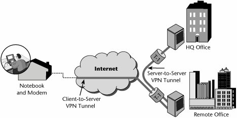
As shown in Figure 9.15, tunneling is generally done by encapsulating the private network data and protocol information within the public network transmission units so that the private network protocol information appears to the public network as data. Tunneling allows the use of the Internet, which is a public network, to convey data on behalf of a private network. VPN tunneling is not intended as a substitute for encryption and decryption. In cases where a high level of security is necessary, the strongest possible encryption should be used within the VPN, and tunneling should serve only as a convenience. Some tunneling protocols include encryption: PPTP includes MPPE (Microsoft Point-to-Point Encryption, based on RC-4), and IPsec specifies a tunnel mode typically used in gateway-to-gateway (but not client-to-gateway) communications. (VPN security is covered in detail later in this chapter.)
Figure 9.15. VPN tunneling
Customers and providers can employ various flavors of point-to-point tunnels to serve as logical links in an IP VPN. An IP VPN tunnel connects two sites or a user to a site by imposing a separate tunnel header on the VPN data packet at the source site and disposing of the tunnel header at the destination site. This lets VPN data packets travel opaquely through the public Internet, independent of their payload or header content.
Applications of VPNs
A VPN is an architecture, a series of products and software functions tied together and tightly calibrated. Managing a VPN entails dealing primarily with two issues: monitoring security policies and parameters, and ensuring that applications function within the latency requirements. It is important to be able to effectively and easily manage the VPN environment. You need to consider how easy it is to track a VPN's tunnel traffic, support policy management, track QoS, track security infractions, and support public key certificate authorities (CAs). Managed VPN servicesthe one-stop-shopping approach to VPNsare designed to lock in users and to reduce costly customer churn, but with this approach, interoperability is very restricted. Managed VPNs provide capabilities such as IP connection and transport services, routers, firewalls, and a VPN box at the customer site. Benefits of this approach include the fact that it involves a single service vendor, SLAs, guaranteed latency and bandwidth, and the security of traffic being confined to one network.
VPN applications provide maximum opportunities to save money and to make moneyby substituting leased lines with Internet connectivity, by reducing costs of dialup remote access, and by stimulating new applications using extranets. These savings can be substantial.
The three major applications of VPNsintranets (i.e., site-to-site VPNs), remote access, and extranetsare examined in the following sections.
Intranet VPNs
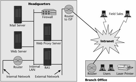
Intranet VPNs are site-to-site connections (see Figure 9.16). The key objective of an intranet VPN is to replace or reduce the use of leased-line networks, traditional routers, and Frame Relay services. The cost savings in moving from private networks to Internet-based VPNs can be very high, in the neighborhood of 50% to 80% per year. Remember that Internet-based VPNs allow less control over the quality and performance of applications than do provisioned VPNs; this is a bit of a deterrent, and many clients still want to consider Frame Relay or ATM-based VPNs, which provide better QoS. The savings might drop a bit, but the cost of a provisioned VPN would still be substantially less than the cost of using leased lines.
Figure 9.16. An intranet VPN
There are two key barriers to building more intranets based on VPNs: First, there is a variance between vendors' products that leads to interoperability problems, and second, today's Internet is unable to provide end-to-end QoS.
Remote Access VPNs
The most interesting and immediate VPN solution for most customers is the replacement of remote access servers. VPN remote access implementations can save customers from 30% to 70% over traditional dialup remote access server deployment. Remote access servers provide access to remote users, generally via analog plain old telephone service (POTS) lines, or, perhaps, ISDN connections, including dialup protocols and access control for authentication (administered by the servers). However, a remote access server requires that you maintain racks of modems, the appropriate terminal adapters for ISDN services, or DSL-type modems for DSL services. You also need remote access routers, which connect remote sites via a private line or public carriers and provide protocol conversion between the LANs and WANs. To have an internal implementation of remote access, you have to acquire all these devices, as well as the talent to maintain them.
If an enterprise needs remote access connections outside local calling areas, and/or if it needs encrypted communications, it is generally fairly easy to justify a VPN service rather than an enterprise-based remote access server. The initial cost of hardware for a VPN approach is about 33% less than the cost of hardware for a traditional dialup remote access server deployment. The customer also saves on charges for local access circuits, and costly toll and international charges are eliminated.
By virtue of supporting a greater range of customers, a service provider that offers VPN-based remote access is more likely to support a wider variety of broadband access options, including xDSL, cable modems, and broadband wireless. VPN-based remote access also reduces the management and maintenance required with modem banks and remote client dial-in problems. For these reasons, remote access represents the primary application for which customers turn to VPNs. Figure 9.17 shows an example of a remote access VPN.
Figure 9.17. A remote access VPN
Extranet VPNs
Extranet VPNs allow an external organization to have defined access to an enterprise's internal networks and resources (see Figure 9.18). There are three major categories of extranets: supplier extranets, which focus on speeding communications along the supply chain; distributor extranets, which focus on the demand side and provide great access to information; and peer extranets, which create increased intraindustry competition.
Figure 9.18. An extranet VPN
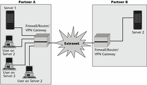
The key applications for extranets include distribution of marketing and product information, online ordering, billing and account history, training policies and standards, inventory management, collaborative research and development, and e-mail, chat, news, and content.
Benefits and Evolution of VPNs
The main benefit of VPNs as compared to leased-line or Frame Relay networks is cost savings. VPNs also optimize environments that use IP; they have less overhead than Frame Relay, and tunneling protocols may eliminate the need for proprietary encapsulation of protocols. Provisioned VPNs also have the additional benefits of Frame Relay and ATM in the administration of virtual circuits and QoS. VPNs also provide the capability to support dialup access, and greater redundancy is achieved in the network by virtue of meshed nets. In addition, VPNs do not necessarily demand an end-to-end digital fiber infrastructure.
VPNs are undergoing an evolution, and various parameters still need to be addressed. Among those are the QoS guarantees. Effective traffic prioritization is at the heart of QoS, and currently available mechanisms include Differentiated Services (DiffServ), Class-Based Queuing (CBQ), Common Open Policy Service (COPS), and MPLS. (These mechanisms are covered in Chapter 10.) Other areas of evolution in VPNs are tiering of VPN services (i.e., bandwidth tiering and different policy management), the capability to support autoprovisioning, and the emphasis on security.
QoS and security are the two most important considerations in administering VPNs, so uptimes, delays, and SLAs need to be structured. For example, QoS guarantees could promise 100% premises-to-premises network availability, with a maximum latency of 80 milliseconds. Some vendors offer separate SLAs for dedicated and remote access. For dedicated access, the SLA may offer an availability guarantee of 99.9% and a maximum latency guarantee of 125 milliseconds. On remote access SLAs, a busy-free dial availability guarantee of 97% may be stipulated, and the latency guarantee would depend on the initial modem connection speed.
Today, three basic types of carrier-managed IP VPN services are offered:
- CPE-based IPsec VPNs These VPNs are generally used to support site-to-site enterprise VPNs and have, in many ways, become the gold standard for VPN security, especially when traffic is running over the public Internet.
- Network-based IPsec VPNs These VPNs may run over the Internet or the service provider's private IP facilities. Customers use leased-line connections from the premises router to the service provider's POP.
- Network-based MPLS VPNs These VPNs are receiving the most attention today. Service providers' VPN solutions can be deployed using partial mesh, full mesh, and hub-and-spoke designs. They can provide point-to-point and multipoint connectivity. They support a multitude of services and are available from multiple providers around the world.
VPN Standards
The initial VPN service standardization efforts focused on service provider Layer 3 solutions, where multiple competing implementations had already been developed. The main driving forces of the standards initiatives included multivendor interoperability and applicability scenarios of each of those Layer 3 solutions. Later, the interest in Layer 2 provider edgebased solutions was driven by the growing attractiveness of the metro-Ethernet market and the capability to offer relatively simple migration paths from traditional Layer 2 ATM and Frame Relay services to network-based VPNs over an IP infrastructure.
The ITU-T has been mainly developing requirements, architecture elements, and Layer 1 architectures and is currently working on generalized VPN architectures and QoS aspects. The IETF has focused on Layer 3 and Layer 2 solutions and related applicability scenarios. Finally, the Ethernet-based Layer 2 VPN domain covers areas of interest for various standards communities. The Metro Ethernet Forum (www.metroethernetforum.org) is one of the major groups working on solutions to offer Ethernet Layer 2 VPNs using Ethernet metro or core networks.
Types of IP VPNs
IP-based VPNs were initially deployed to address two specific market segments:
- Virtual private dial networks (VPDNs) VPDNs were developed for telecommuters and road warriors who needed secure and convenient access to their enterprise servers (see Figure 9.19). This approach has included the use of PPTP, L2TP, or IPsec. With a VPDN, the end user establishes a user-to-corporate-gateway point-to-point session that travels over a combination of two links: a dialup data link to the Internet service provider edge and a VPN tunnel (sometimes called a voluntary tunnel) from the user to the enterprise gateway (less common is a compulsory tunnel, established from the ISP edge to the enterprise gateway). L2TP supports the tunneling of PPP sessions containing user data through the Internet, but by itself isn't secure; L2TP connections are clear text. L2TP is usually combined with IPsec to achieve the required privacy. Residential dialup access to the Internet uses similar technology. Broadband provides additional options, including the use of cable links, DSL links, or 802.11 in the wireless realm.
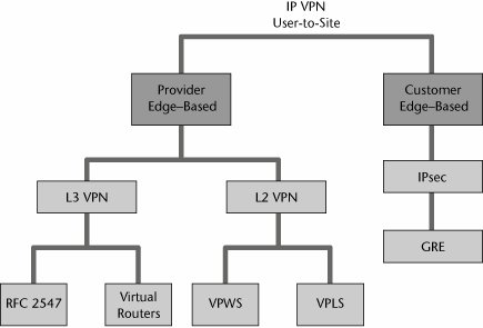
- Site-to-site VPNs Site-to-site VPNs were developed for enterprises desiring to communicate over the public Internet but requiring data integrity authentication and privacy. The main approach has included the use of IPsec or GRE. However, many more options are now available, especially in the provider edgebased arena. As shown in Figure 9.20, provider edgebased VPNs are available as Layer 3 VPNs and Layer 2 VPNs. Layer 3 VPNs offer two choices: RFC 2547 and virtual routers. Layer 2 VPNs also offer two choices: virtual private wire service (VPWS) and Virtual Private LAN Services (VPLS).
Figure 9.19. VPDN solutions
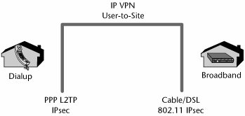
Figure 9.20. Site-to-site VPN solutions
The following sections describe the various types of site-to-site VPNs.
IPsec VPNs
IPsec has been around for quite some time and is offered by most service providers as a mechanism for tunneling traffic across the Internet to areas where the provider does not have POPs. In order to address the heightened security requirements, the customer or the provider managing the CPE routers can build IPsec security associations (not called tunnels unless using a specific type of security association, known as tunnel mode, described shortly) across the Internet to interconnect CPE. In order to authenticate and encrypt the user data, packets are forwarded across the shared Internet. IPsec uses a variety of protocol exchanges and encapsulations at the endpoints.
IPsec is an IETF protocol suite that addresses basic data integrity and security. It covers encryption, authentication, and key exchange. It supports key sizes of varying lengths, depending on the capabilities of each end of the connection. IPsec emphasizes security by authenticating both ends of the connection, negotiating the encryption protocol and key for the encrypted session, and encrypting and decrypting the session establishment data. IPsec provides secure transmission of packets at the IP layer, including authentication and encryption of the packets. This is accomplished by using the authentication header and encapsulating security payload features of IPsec.
IPsec uses transport and tunnel modes. In transport mode, only the IP payload is encrypted. There is no change to the original IP header. This is generally used between hosts or routers and also in client/server VPNs. In tunnel mode, the entire IP datagram is encrypted; the original packet is encapsulated in IPsec and given a new IP header. This mode is generally used between gateways.
Initially, IPsec became the predominant mechanism for providing the underlying VPN architectures. This technology works at OSI Layer 3 to create a connection into the network so that as a device logs on, it can act as if it is physically attached to the LAN. By encrypting the traffic, the customer can build VPN networks over the Internet. A customer's traffic is encrypted but not necessarily segmented. IPsec provides encryption and authentication, but there is a tradeoff in performance, although most modern hardware can handle the cryptographic requirements well enough. In general, IPsec is inefficient because it requires significant overhead to encrypt the traffic. This may be acceptable on low-speed links, but throughput is significantly affected on high-speed links. Most router vendors provide IPsec capabilities embedded in the operating systems, but there is a significant performance degradation in the routers.
Line-speed IPsec processing is still not where most customers would like it to be. You need to take this into consideration when choosing a routing platform that will be initiating IPsec security associations. In addition to the performance impact, there is the additional management overhead of configuring, maintaining, and managing IPsec across the IP cloud. IPsec, key distribution, key management, and peering configuration can become complex in a large IPsec deployment.
GRE VPNs
RFC 2784 and RFC 1702 specify the GRE protocol for using IP as both the delivery and payload protocol. In the most general case, a system has a packet that needs to be encapsulated and delivered to some destination, referred to as the payload packet. The payload is first encapsulated in a GRE packet. The resulting GRE packet can then be encapsulated in some other protocol and forwarded. This outer protocol is referred to as the delivery protocol.
GRE is a simple stateless protocol that allows for the tunneling of IP in IP. GRE tunnels can be used to form VPNs, connecting remote sites by using private IP addresses via a public network. These tunnels are configured between provider edge routers and are transparent to the rest of the network. GRE VPNs currently have simple support for QoS. By default, the DSCP value in each payload header is copied into the tunnel header. This means that any QoS policy for IP packets can be applied to GRE-encapsulated packets as well. An added benefit is that GRE VPNs provide adjacencies directly between customer routers.
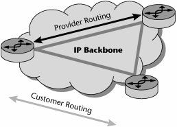
GRE VPNs provide a complete separation between customer and provider routing (see Figure 9.21). Customers can run their own routing protocols across the VPN and have no interaction with provider protocols. An internal gateway protocol dedicated to customers, such as OSPF or IS-IS, can be run across a provider network with strict separation from the provider's internal or external routing protocols. If customers are transitioning from a private enterprise network, they may be able to use this approach to preserve much of their internal gateway protocol configuration.
Figure 9.21. IP GRE VPNs
Key concepts in GRE VPNs include multiple contexts and multiple interfaces:
- Contexts A GRE router's VPN solutions all rely on contexts, which are virtual routers running within single physical devices. A context has its own IP address space, routing table, user authentication, logging and debugging functions, and other attributes. Customers get a dedicated context for each VPN.
- Interfaces Virtual or logical interfaces enable physical ports or circuits to be individually mapped to different contexts through simple configuration commands. An interface is a logical entity that holds an IP address and is configured as part of a context. Interfaces are independent of physical ports and circuits. An interface can pass traffic only when it is bound to, or associated with, a physical port or circuit. This binding process can be changed at any time so that a customer port can easily be mapped to one context and then remapped to another with only one line of configuration code.
GRE routers can carry multicast traffic in GRE tunnels. Carriers can, therefore, distribute multicast traffic, such as video, in GRE VPNs or use GRE tunnels to carry multicast traffic through a unicast network. The latter application is ideal when a carrier wants to support multicast capability in only certain select routers or segments of the network. A provider can support GRE VPNs as only the first step in its VPN strategy. If the provider wants to eventually offer Border Gateway Protocol (BGP) and MPLS VPNs, it can continue to offer GRE VPNs while the network is migrated to MPLS and the BGP mesh between provider edge routers is configured. Then the provider can migrate GRE VPN customers to be BGP MPLS VPNs (which are discussed later in this chapter, in the section "RFC 2547 (BGP MPLS) VPNs").
Layer 3 VPNs
The objective of Layer 3 VPNs is to virtualize multiple per-VPN forwarding instances within a single physical platform. This offers new customer IP VPN services, reduces capital and operational expenditures, offers scalability, and provides percontrol plane protection, isolation, and security. The provider forwards packets based on customer Layer 3 addresses, and the customer does less routing because the provider assists in distributing customer routes to VPN sites.
The basic components of a Layer 3 VPN are the provider, provider edge, and customer edge routers. The provider routers are IP or MPLS routers found in the core, and they interconnect the provider edge routers at the edge. A provider edge router sits at the edge of the provider's network and provides the interface between the customer edge router and the IP or MPLS backbone. The customer edge routers exchange their routing tables with the provider edge routers via standard routing protocols, such as RIP, OSPF, Enhanced Interior Gateway Routing Protocol (EIGRP), and BGP.
As shown in Figure 9.22, the provider edge devices that implement the VPN functionalities implement a set of per-VPN virtual forwarding instances (VFIs). A VFI is a logical entity that resides at a provider edge that includes the router information base and forwarding information base for a VPN instance. A separate forwarding or switching instance is dedicated to one specific VPN. Customer edgesourced packets are forwarded across the provider backbone in a tunnel based on a per-VPN VFI lookup of destination customer Layer 3 addresses. VFIs make forwarding decisions based on the VPN customer packet Layer 3 information (i.e., the packet destination IP address).
Figure 9.22. The provider edge-based Layer 3 reference model
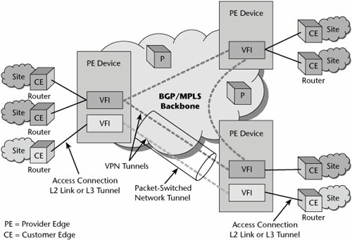
VFI entities implemented in different provider edge devices on the same service provider network and belonging to the same VPN are interconnected via VPN tunnels. As mentioned earlier in this chapter, a VPN tunnel is a virtual link between two entities that belong to the same VPN. This virtual link is implemented by means of adding an encapsulation header to each forwarded packet, and that header is understood by the packet-switched network backbone in such a way that the encapsulated traffic can be forwarded from the packet-switched network source entity to the packet-switched network destination entity. The source entity is responsible for adding the encapsulation header, and the destination entity is responsible for removing it. Multiple VPN tunnels established between the same two provider edge devices are often multiplexed in a provider edgetoprovider edge packet-switched network tunnel and transparently carried over the packet-switched network's provider core devices.
The customer site is a local private networkthat is, a set of communication devices that do not use a shared backbone to communicate with each other. The edge devices of a site, the customer edge routers, are connected to one of the service provider's provider edge devices via an access connection or attachment circuit through the access network. An access connection in this context is a dedicated Layer 2 connection, such as an ATM virtual circuit, a Frame Relay data link connection identifier (DLCI), a PPP connection, an Ethernet interface, or a virtual LAN. It could also be a Layer 3 tunnel, such as an IPsec security association over the Internet. The customer edgetoprovider edge access connection is configured to be associated with the specific VFI in the provider edge, depending on which VPN the site belongs to.
Layer 3 VPNs are implemented in two ways:
- RFC 2547 (BGP MPLS) VPNs RFC 2547 is an IETF informational document that describes BGP MPLS. RFC 2547bisthe second version of RFC 2547is an Internet Draft. RFC 2547bis VPNs are also known as BGP MPLS VPNs because BGP is used to distribute VPN routing information across the provider's backbone and MPLS is used to forward VPN traffic from one VPN site to another. RFC 2547bis multiplexes many VPN routes through a single BGP system. In this approach, customer routing is terminated at the provider edge.
- Virtual router VPNs With these types of VPNs, each virtual router runs an instance of a routing protocol that is responsible for disseminating VPN reachability information between virtual routers. In this model, customer routing is extended across the provider network.
The following sections describe these two types of Layer 3 VPNs in detail.
RFC 2547 (BGP MPLS) VPNs
IP VPNs based on RFC 2547 are becoming increasingly popular. As shown in Figure 9.23, they use a combination of BGP and MPLS to pass IP traffic through an MPLS core. Offering this type of VPNs requires a provider to configure MPLS on all core and edge routers. Furthermore, all provider edge routers need to have Multiprotocol BGP (MP-BGP) sessions established between them to communicate VPN information. The provider edge routers store the routing updates from each customer's customer edge router in what is termed a virtual routing forwarding (VRF) instance; simply put, it is a routing table populated with VPN routes.
Figure 9.23. The RFC 2547bis model
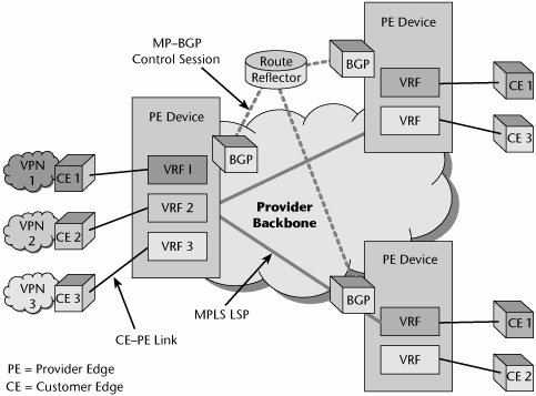
Because there may be a great number of provider edge routers in a network, carriers might also need to configure BGP route reflectors to simplify the internal BGP mesh. Route reflectors reduce the size of the internal BGP mesh. Route reflector clients propagate routes up to the route reflectors, which, in turn, send the routes to other route reflector clients. Route reflectors are useful in partitioning total routing table space across multiple devices. This allows the route reflector clients to receive only routes they neednot all the routes.
Each customer edge router has its own VRF on the provider edge. The customer advertises all routes associated with that location to the provider edge. When all the provider edge routers that connect to a particular customer have the customer's routing information in a VRF, the provider edge routers exchange information by using MP-BGP. These routes and the corresponding VRFs make up the customer VPN.
To the customer, from a routing perspective, the customer edge routers appear as if they are connected via a traditional VPN. The customer can view the routing table on the customer edge router and see routes to remote sites, just as it would with a traditional VPN. The routing adjacencies formed are between the customer edge and the provider edge, not the customer edge and the customer edge. The customer edge has one interface to the MPLS cloud, and the MPLS provides full or partial meshing with the customer edge router attached to the network.
One of the benefits of Layer 3 MPLS VPNs is that the provider handles all the meshing and can provide any-to-any connectivity over a multitude of interface types. Previously, if a customer wanted to mesh its remote locations, it had to purchase leased lines and build a mesh of permanent virtual circuits (PVCs). The routing architecture and propagation of routes was up to the customer; the provider only ensured connectivity. With Layer 3 MPLS VPNs, all that is required is the advertisement of the routes to the provider edge, and the provider handles the rest. The only drawback to this solution is that the provider may not have the geographic footprint to reach all the customer locations; it can be cost-prohibitive for the customer to purchase a local loop to the nearest provider edge router in the provider's POP. This is a limiting factor with MPLS deployment, especially for organizations that have international locations.
Virtual Router VPNs
The objective of a Layer 3 virtual router VPN, which is currently an IETF Internet Draft, is to provide per-VPN routing, forwarding, QoS, and service management capabilities. This VPN service is based on the concept of a virtual router, which has exactly the same mechanisms as a physical router and, therefore, can inherit all existing mechanisms and tools for configuration, deployment, operation, troubleshooting, monitoring, and accounting. Multiple virtual routers can exist in a single physical device, and virtual routers can be deployed in various VPN configurations.
Direct virtual routertovirtual router connectivity can be configured through Layer 2 links or through a variety of tunnel mechanisms, using IP- or MPLS-based tunnels. Also, multiple virtual routers can be aggregated over a backbone virtual router. This architecture accommodates various backbone deployment scenarios, including situations in which the VPN service provider either owns the backbone or obtains backbone service from one or more other service providers.
As shown in Figure 9.24, a VPN customer site is connected to the provider backbone by means of a connection between a customer edge devicewhich can be one or more hosts and/or routersand a virtual router. Customer edge devices are preconfigured to connect to one or more virtual routers. Multiple virtual routers may coexist on the same service provider edge device or provider edge. Customer edge devices can be attached to virtual routers over any type of access link (e.g., ATM, Frame Relay, Ethernet, PPP) or IP tunneling mechanisms (e.g., IPsec, L2TP, or GRE tunnels). Customer edge sites can be statically connected to the provider network via dedicated circuits or can use dialup links. Routing tables associated with each virtual router define the site-to-site reachability for each VPN. The internal backbone provider routers are not VPN aware and do not keep VPN state.
Figure 9.24. Virtual router VPNs
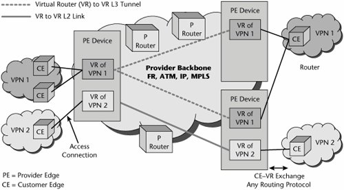
In general, the backbone is a shared network infrastructure that represents either a Layer 2, ATM, or Frame Relay network; an IP network; or an MPLS network. Not all VPNs existing on the same provider edge are necessarily connected via the same backbone, so a single provider edge can be connected to multiple backbones. Individual virtual routers on the provider edge may also connect to multiple backbones. Thus, a single VPN can be built from multiple transport technologies in the virtual router architecture.
Virtual routers have independent IP routing and forwarding tables, and they are isolated from each other. This means that two virtual routers on a provider edge can serve two different VPNs that may have overlapping address space. The addresses need only be unique within a VPN domain. A virtual router has two main functions: constructing routing tables for the paths between VPN sites, by using any routing technology (such as OSPF, RIP, or a border gateway protocol), and forwarding packets to the next hops within the VPN domain.
From a VPN user's point of view, a virtual router provides the same functionality as a physical router. Separate routing and forwarding capabilities provide each virtual router with the appearance of a dedicated router that guarantees isolation from the traffic of other VPNs while running on shared forwarding and transmission resources. To the customer edge access device, the virtual router appears as a neighbor router in the customer edgebased network.
Three main virtual router deployment scenarios can be used for building VPNs: virtual routertovirtual router connectivity over a Layer 2 connection, virtual routertovirtual router connectivity tunneled over an IP or MPLS network, and aggregation of multiple virtual routers over a backbone virtual router to provide connectivity over a Layer 2 IP or MPLS network. These virtual router deployment scenarios can coexist on a single provider edge or within a single VPN.
RFC 2547 VPNs Versus Virtual Router VPNs
Table 9.2 compares the RFC 2547 VPN and virtual router VPN architectures.
|
Characteristic |
RFC 2547 VPNs |
Virtual Router VPNs |
|---|---|---|
|
Is simple to implement |
No |
Yes |
|
Is scalable |
Yes |
No |
|
Is easy to provision new services |
Yes |
No |
|
Provides high security |
No |
Yes |
|
Is a securable network |
Yes |
Yes |
|
Supports many subscribers |
Yes |
No |
|
Requires MPLS/BGP |
Yes |
No |
|
Supports interoperability |
Yes |
No |
|
Provides end-to-end QoS |
Yes |
No |
|
Reduces CPE complexity |
Yes |
Yes |
|
Reduces CPE processing |
Yes |
No |
The standards debate is ongoing, with high-profile companies on both sides of the argument. For now, the choice of a network-based VPN implementation is up to the provider. All these IP VPN services are more complicated to configure and require more attention from both carriers and customers than Frame Relay, private-line, or ATM services. Without any application or architectural triggers for the customer to move to IP VPN service, the shift may be very gradual.
Layer 2 VPNs
Carriers need to continue to benefit from legacy services such as TDM private lines, Frame Relay, and ATM while they introduce new Ethernet metro-transport and Ethernet access services. They need a common edge infrastructure that supports both new and legacy services and allows all the services to seamlessly communicate. To accomplish this goal, most carriers are planning to simplify their network infrastructures over a common MPLS core and introduce MPLS-based services.
MPLS was first deployed in the core of carrier networks to enhance the performance and capabilities of connectionless IP routing. Today, there is increased interest in MPLS Layer 2 VPN services. With MPLS Layer 2 VPN services, carriers can transport protocols such as SNA, DECnet, or IPX and keep legacy TDM private lines as well as Frame Relay and ATM services. With Layer 2 VPNs, the provider forwards packets based on Layer 2 information or port information. It emulates Layer 2 WAN or LAN connectivity between customer sites. In this case, the customer is responsible for the Layer 3 routing. Layer 2 MPLS VPNs are identical to private network VPNs in that the customer attaches its customer premises router to the MPLS cloud via traditional Layer 2 circuits and builds a Layer 3 routing topology over the provisioned circuits. The management of the routing is handled by the customer in the same fashion as it would be with a traditional private VPN.
In a Layer 2 VPN solution, there is no exchange of routing information between the provider edge and the customer edge. The IP/MPLS service provider core network transports customer Layer 2 frames from ingress provider edge to egress provider edge. The VPN tunnels that transport this traffic between provider edges are called pseudo-wires, as they emulate the behavior of a connection or wire over a connectionless infrastructure. The provider edges implement Layer 2 VFIs that forward the customer traffic based on Layer 2 information (e.g., ATM virtual path identifiers and virtual circuit identifiers, or Ethernet MAC addresses, or Frame Relay DLCIs). This is beneficial for organizations that need legacy protocol support and those that feel they can efficiently and cost-effectively manage their own routing environment. They are, in effect, purchasing bandwidth, not the additional services offered by a Layer 3 MPLS VPN. Customers still have the PVC mesh, provisioning, and routing issues, as before, and there may be limitations on what interfaces a carrier will support. Carriers that are evaluating Layer 2 VPNs are challenged by the interconnectivity issues associated with Layer 2 VPNs. Support for any-to-any connectivity over Layer 2 MPLS backbones is not widely deployed by any of the major carriers. In most instances, the customer edge routers require common access types, such as Frame RelaytoFrame Relay or ATM-to-ATM. Ultimately, however, Layer 2 MPLS VPNs will allow customers to attach any Layer 2 access circuit to the MPLS cloud, allowing for diverse and cost-effective interface options.
Multiple Layer 2 VPN service models are being analyzed in the industry and by the Provider Provisioned Virtual Private Networking (PPVPN) working group and the Pseudo-Wire Emulation Edge-to-Edge (PWE3) working group. The PPVPN group is working on the Kompella draft, named after Cureda Kompella. The Kompella draft makes use of BGP to allow provider edge routers to communicate with one another about their customer connections. The PWE3 group is working on a draft named the Martini draft, after Luca Martini. The Martini draft makes use of the Label Distribution Protocol (LDP) between provider edge routers. Two of the most important Layer 2 VPN models, VPWS and VPLS, are described in the following sections.
VPWS
VPWS VPNs are also known as point-to-point pseudo-wires. A pseudo-wire emulates a point-to-point link and provides a single service perceived by its user as an unshared link or circuit of the chosen service. Using encapsulated pseudo-wire tunnels, customers' sites can be connected via point-to-point circuits as if they were using their own private leased lines (see Figure 9.25). VPWS VPNs support traffic types such as Ethernet, ATM, Frame Relay, SDH/SONET, and TDM. VPWS provides a mesh of point-to-point customer edgetocustomer edge Layer 2 connections over a packet-switched network. The provider edge does the mapping between the attachment circuit and the pseudo-wire.
Figure 9.25. VPWS
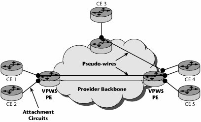
VPWS is seen largely as an appropriate approach for point-to-point connection-oriented services, such as ATM, Frame Relay, and point-to-point Ethernet. For multipoint-to-multipoint connectionless services such as Ethernet and VLANs, VPLS is required.
VPLS
A number of vendors have adopted the VPLS approach, and deployments of VPLS are mushrooming worldwide. VPLS is a growing solution for providing Ethernet services. It combines the benefits of Ethernet and MPLS for both customers and carriers.
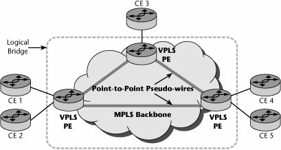
VPLS offers at Layer 2 what IP VPNs offer at Layer 3: a service with multipoint connectivity (see Figure 9.26). The main difference is the interface used between the customer edge equipment and the provider edge equipment. With IP VPNs, customer edge equipment is IP routers, whereas with VPLS, it can be an Ethernet bridge, a switch, a hub, or a router, allowing non-IP traffic as well as IP traffic to be exchanged between sites. Apart from this essential difference, MPLS Layer 2 VPNs and Layer 3 VPN-based approaches are very similar in other areas. Both share the same common MPLS protocols and the underlying IP/MPLS infrastructure. In the past, these services were most commonly delivered on TDM, Frame Relay, and ATM networks. VPLS is one of the most innovative and easily manageable ways of providing Ethernet MPLS VPNs. Each customer location is attached to a node on the MPLS network. For each customer or VPN, a full mesh of logical point-to-point connections is set up over the backbone MPLS network. This allows a customer location to have direct visibility to every other location belonging to that customer.
Figure 9.26. VPLS
Unique MPLS labels are used to segment one customer's traffic from another's and to segment one service from another. This segmentation allows a customer to acquire a bundle of services from its provider, each of which is tailored for the end application. For example, a customer's bundle could comprise VoIP, Internet access, and maybe two or more VPN services. The first VPN service could be to provide broad data connectivity between all corporate locations, accessible to all employees. The second VPN service could be restricted to some financial transactions conducted between a subset of locations. Each of these services would be uniquely configured over VPLS, thus allowing them to have unique quality and security attributes.
VPLS provides logical LAN bridging or switching functions over a packet-switched network. The provider edge performs virtual bridging or switching for LAN-attached customer edge nodes. VPLS supports both point-to-multipoint and multipoint-to-multipoint service using PWE3. PWE3 specifies the encapsulation, transport, control, management, interworking, and security of services emulated over packet-switched networks.
The benefits to carriers of combining Ethernet and MPLS are numerous. Carriers immediately benefit from the lower capital expenditure required for deploying Ethernet infrastructure. However, a simple Ethernet switched network has limitations on service scalability due to VLAN ID restrictions as well as limitations on reliability (e.g., Spanning Tree Protocol does not scale well). These limitations are solved by MPLS, which offers a portfolio of solutions that provide massive scalability and multiple reliability options and also bring other benefits. For example, MPLS's dynamic signaling is instrumental in providing quicker changes and reconfigurations of service. Its traffic engineering capabilities allow providers to support service-level guarantees across the entire network. Thus, it not only meets their needs for scalability and reliability but also provides operational advantages that can further reduce expenditures.
The advent of the Internet and the resulting productivity gains spurred by the adoption of new technologies are leading to a demand for increased bandwidth and services. Corporations are demanding customized services at greater bandwidth, and consumers are looking for services such as broadband connectivity and VOD. Carriers have to balance the demands of their target markets with the realities of their business. Traditional technologies (such as ATM and SDH/SONET), while being familiar, simply do not match the vision that carriers have for their networks. They are built on expensive infrastructure that cannot scale without large investments. Moreover, the complex management and multiple handoffs between all these technologies cause significant operating overhead. The market opportunity for Ethernet services is clear and exists today. Numerous early adopters have been successful in deploying these services. Carriers are facing a challenge in how to respond to these market dynamics. VPLS with an Ethernet infrastructure can present an optimal solution for carriers to roll out new services profitably. The benefits from reduced capital and operating expenditures add up quickly to improve the bottom line. In addition, the ability to leverage existing networks ensures carriers that the investments made in older technologies can be preserved and that more returns can be generated from them. There are, however, potential disadvantages associated with the use of Ethernet in MANs and WANs. The biggest concern is the lack of QoS capabilities, leading some industry observers to view Ethernet solutions as one of throwing bandwidth at the problem and therefore a short-term strategy at best.
VPN Security
Security is very important to the proper operation of VPNs. The following sections describe the available security mechanisms, including firewalls; authentication, authorization, and accounting (AAA); encryption; and digital certificates.
Firewalls
A firewall is typically defined as a system or a group of systems that enforces and acts as a control policy between two networks. It can also be defined as a mechanism used to protect a trusted network from an untrusted networkusually while still allowing traffic between the two. All traffic from inside to outside and vice versa must pass through the firewall. Only authorized traffic, as defined by the local security policy, is allowed to pass through it. The system itself is highly resistant to penetration. A firewall selectively permits or denies network traffic.
There are several variations of firewalls, including the following:
- A firewall can use different protocols to separate Internet servers from internal servers.
- Routers can be programmed to define what protocols at the application, network, or transport layer can come in and out of the routerso the router is basically acting as a packet filter.
- Proxy servers can separate the internal network users and services from the public Internet. Additional functions can be included via proxy servers, including address translation, caching, encryption, and virus filtering.
Authentication, Authorization, and Accounting
An important aspect of security is the authentication of users and access control, which is commonly handled by an AAA server. An AAA server is a network server used for access control. Authentication identifies the user, authorization implements policies that determine which resources and services a valid user may access, and accounting keeps track of time and data resources used for billing and analysis. The AAA server, also called 3A software, typically interacts with a network access server (NAS) and gateway servers, as well as with databases and directories that contain user information.
RADIUS, the current standard by which devices or applications communicate with an AAA server, is an AAA protocol for applications such as network access or IP mobility. This UDP-based protocol is intended to work in both local and roaming situations and is considered suitable for high-volume service control applications, such as regulation of dialup or VPN services. Increased use of RADIUS is occurring due to the introduction of 802.1X port security (discussed in Chapter 15, "WMANs, WLANs, and WPANs") for wired and wireless LANs. In fact, Microsoft has included 802.1X security in Windows TCP/IP, and every enterprise PC might require authentication before being granted access to the LAN.
RADIUS servers are designed to block unauthorized access by remote users, and they rely on authentication schemes such as Challenge Handshake Authentication Protocol (CHAP), which means there's a back-and-forth dialog to verify a user's identity. In fact, RADIUS makes use of CHAP, which uses a three-way handshake to periodically verify the identity of the peer throughout the connection. The server sends a random token to the remote workstation. The token is then encrypted, using the user's password, and sent back to the server. The server performs a lookup to see whether it recognizes the password. If the values match, the authentication is acknowledged; if the values do not match, the connection is terminated. Because a different token is provided each time a remote user dials in, CHAP provides robust authentication.
A newer protocol, called DIAMETER, serves as a replacement for RADIUS. DIAMETER is also an AAA protocol for the same applications of network access and IP mobility. The major change is that DIAMETER extends RADIUS to provide AAA services to new access technologies.
Encryption
The best way to protect electronic data is to use encryptionthat is, to encode the data so as to render a document unreadable by all except those who are authorized to have access to it. Encryption and decryption are performed by using a cipher, which is an algorithm, or a series of well-defined steps that can be followed as a procedure. The content of an original document is referred to as plaintext. When encryption is applied to the document, the plaintext is scrambled, through the use of an algorithm and a variable, or key; the result is called ciphertext. The key is a randomly selected string of numbers. Generally, the longer the string, the stronger the security.
Although encryption may ensure privacy, other techniques are required for full communications security, including a message authentication code or digital signatures, both used to verify the authenticity and integrity of the message. The message authentication code is a tag, or short piece of information, used to authenticate a message. Using a secret key and an arbitrary-length message, a message authentication code algorithm calculates a hash value, which protects the message's integrity and authenticity by allowing those who also have the secret key to detect any changes that may have been made to the message content. The same secret key is used to both generate and verify the message authentication code values. Digital signatures, on the other hand, use two complementary algorithms: one for signing the message and the other for verification. Digital signatures rely on public key cryptography (discussed later in this chapter).
There are two major categories of encryption algorithms: symmetric and asymmetric.
Symmetric Encryption
In symmetric encryption, the sender and the receiver use the same key or machine setup. There are two approaches to encoding data using symmetric encryption: block cipher and streaming cipher. With the block cipher approach, the algorithm encodes text in fixed-bit blocks, using a key whose length is also fixed in length. With the streaming cipher approach, the algorithm encodes the stream of data sequentially, without segmenting it into blocks. Both of these techniques require a secure method of reexchanging keys between the participants.
Symmetric encryption algorithms include the following:
- Data Encryption Standard (DES) DES, which was developed in the 1970s, is very popular in the banking industry. It is a block cipher that encodes text into fixed-bit blocks (typically 64 bits), using a 56-bit key. DES has been replaced by Advanced Encryption Standard (AES).
- Triple DES (3DES) 3DES is 168-bit encryption that uses three 56-bit keys. 3DES applies the DES algorithm to a plaintext block three times.
- Rivest Cipher 4 (RC4) RC4 is a streaming cipher technique; a stream cipher adds the output of a pseudorandom number generator bit by bit to the sequential bits of the digitized plaintext.
- Blowfish Blowfish is a 64-bit block code that has key lengths of 32 bits to 448 bits. Blowfish is used in more than 100 products and is viewed as one of the best available algorithms.
- International Data Encryption Algorithm (IDEA) IDEA, developed by ETH Zurich (www.ethz.ch), is free of charge for noncommercial use. It is viewed as a good algorithm and is used in Pretty Good Privacy (PGP) and in Speak Freely, a program that allows encrypted digitized voice to be sent over the Internet.
- Twofish Twofish, developed by Bruce Schneier of Counterpane Internet Security (www.counterpane.com), is very strong, and it was one of the five initial candidates for AES.
- Advanced Encryption Standard (AES) AES was adopted by the National Institute of Standards (NIST; www.nist.gov) in November 2001 after a five-year standardization process.
According to NIST, it would take 149 trillion years to crack the U.S. government's AES, which uses the Rijndael algorithm and specifies three key lengths128 bits, 192 bits, and 256 bits. In comparison, DES, which uses a 56-bit key, would take only a matter of hours using a powerful computer, but, of course, this is totally dependent on the speed of the hardware used for cracking the code; a typical desktop PC would require much more than a few hours to crack a 56-bit DES key.
Asymmetric Encryption
Key encryption requires a secure method for exchanging keys between participants. The solution to key distribution came, in 1975, with Diffie and Hellman's public key cryptography scheme. This permits the use of two keys, one of which can be openly published and still permit secure encrypted communications. This scheme later became known as asymmetric key cryptography (also called public key encryption [PKE]).
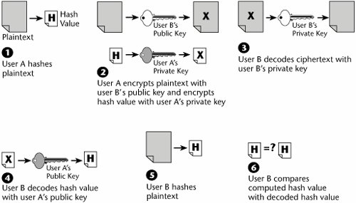
Asymmetric cryptography can be used for authentication. After encrypting a signature by using a private key, anyone with access to the public key can verify that the signature belongs to the owner of the private key. As shown in Figure 9.27, the following are the steps in PKE:
|
1. |
User A hashes the plaintext. |
|
2. |
User A encrypts the plaintext with user B's public key and encrypts the hash value with user A's private key. |
|
3. |
User B decodes the ciphertext with user B's private key. |
|
4. |
User B decodes the hash value with user A's public key, thereby confirming the sender's authenticity. |
|
5. |
User B calculates the hash value of the just-encrypted plaintext. |
|
6. |
User B compares the decrypted hash value with the value calculated locally, thereby confirming the message's integrity. |
Figure 9.27. Encryption and authentication
Public key management involves the exchange of secrets that both ends use to produce random short-term session keys for authenticating each other. It is a method of encrypting data by using two separate keys or codes. The sender uses a public key generally provided as part of a certificate issued by a CA to scramble data for transmission. The receiver then uses the corresponding private key to decrypt the data upon receipt. The CA issues certificates that contain data about individuals or enterprises that has been verified to be authentic (although not all public CAs do this). In essence, the CA vouches for the authenticity of other parties so that their communications are secured.
Message authentication verifies the integrity of an electronic message and also verifies that an electronic message was sent by a particular entity. Before an outgoing message is encrypted, a cryptographic hash functionwhich is like an elaborate version of a checksumis performed on it. The hash function compresses the bits of the plaintext message into a fixed-size digest, or hash value, of 128 or more bits. It is then extremely difficult to alter the plaintext message without invalidating the hash value.
Message authentication mechanisms include Message Digest-5 (MD5) and Secure Hash Algorithm-1 (SHA-1). MD5 hashes a file of arbitrary length into a 128-bit value. SHA-1 hashes a file of arbitrary length into a 160-bit value; it is more processor intensive, but it renders greater security.
Public key management provides a secure method for obtaining a person's or an organization's public key, with sufficient assurance that the key is correct. There are three main public key algorithms: RSA (named for its creators, Rivest, Shamir, and Adelman), Diffie-Hellman, and PGP. RSA is the oldest of the three algorithms, and its security derives from the difficulty of factoring the product of two large prime integers. Diffie-Hellman is used mostly for exchanging keys; its security rests on the difficulty of computing discrete algorithms in a finite field, generated by a large prime number. PGP (www.pgp.com), which was created in 1991, is one of the most popular PKE schemes.
Public Key Infrastructure
Without a functioning universal public key infrastructure (PKI), we cannot reliably and easily acquire certificates that contain public keys for persons or organizations we want to communicate with. One of the biggest hurdles e-commerce companies face is confirming the identity of the parties involved. Ensuring identity requires an encrypted ID object that can be issued by a mutually trusted third party (i.e., a CA) and then verified and accepted by a user's browser. Personal digital IDs contained in the user's browser accomplish this. Historically, these client certificates have been used to control access to resources on a business network, but they can also contain other user information, including identity discount level or customer type. The user's browser reads the server certificate, and if it's accepted, the browser generates a symmetric session key, using the server's public key. The server then decrypts the symmetric key, which is then used to encrypt the rest of the transaction. The transaction is then signed, using the user's digital ID, verifying the user's identity and legally binding the user to the transaction.
PKI is a system that provides protocols and services for managing public keys in an intranet or Internet environment; it involves distributing keys in a secure way. PKI secures e-business applications such as private e-mail, purchase orders, and workflow automation. It uses digital certificates and digital signatures to authenticate and encrypt messages. It permits the creation of legally verifiable identification objects, and it also dictates an encryption technique to protect data transmitted over the Internet.
Usually, PKI involves client software, server software such as a CA, hardware (e.g., smart cards), and operational procedures. Using his or her private key, one user digitally signs a message, and the receiver, using the public key contained in the sender's certificate, issued by a CA within the PKI, can check that signature. In this fashion, two or more users can establish confidentiality, message integrity, and user authentication without having to exchange any special information in advance. PKI systems used in the enterprise are generally closely linked to the enterprise directory system, where each employee's public key is often stored, along with his or her general contact information. The leading directory technology is LDAP, which is discussed in Chapter 10.
Standards are absolutely vital to proper PKI operation, given that there is a certificate hierarchy composed of at least several computers and often more than one organization, using interoperating software from different sources. The group responsible for developing standards in this area is the IETF PKIX working group (www.imc.org/ietf-pkix). This group's purpose is to develop the Internet standards needed to support an X.509-based PKI. (X.509 is discussed in the next section.)
Overall, the market for commercial PKI operations has not bloomed as its pioneers imagined. Too many differences in enacted laws and regulations, not to mention technical and operational problems, have slowed progress tremendously.
Digital Certificates
Digital certificates, based on the ANSI X.509 specification, have become a de facto Internet standard for establishing a trusting relationship by using technology. X.509 comes from the X.500 specification on directory services, which serves as an electronic phonebook, allowing enabled applications to look up included entities. Each entity has an identifying record or certificate, and that certificate follows the ITU X.509 recommendation. Using digital certificates is a method for registering user identities with a third party, a CA (such as Entrust or VeriSign). A digital certificate binds a user to an electronic signature that can be trusted like a written signature and includes authentication, access rights, and verification information. CAs prepare, issue, and manage the digital certificates, and they keep a directory database of user information, verify its accuracy and completeness, and issue the electronic certificates based on that information. A CA signs a certificate, verifying the integrity of the information in it.
By becoming their own digital CAs, service providers can package electronic security with offerings such as VPN and applications services. Server certificates ensure Internet buyers of the identity of the seller's Web site. They contain details about the Web site, such as the domain name of the site and who owns it. Third parties, such as Thawte (www.thawte.com), then guarantee this information. Sites with server certificates post the CA, and Internet browsers accept their certificates for secure transactions.
There are still many security developments to come, especially with the constant introduction of new networking technologies and systems. Standards need to be defined and formalized for the likes of the various IP services and wireless/mobile networks before e-commerce will truly be able to function with the security that it mandates. For now, these are the types of mechanisms necessary to ensure that your data remains with you.
Part I: Communications Fundamentals
Telecommunications Technology Fundamentals
- Telecommunications Technology Fundamentals
- Transmission Lines
- Types of Network Connections
- The Electromagnetic Spectrum and Bandwidth
- Analog and Digital Transmission
- Multiplexing
- Political and Regulatory Forces in Telecommunications
Traditional Transmission Media
Establishing Communications Channels
- Establishing Communications Channels
- Establishing Connections: Networking Modes and Switching Modes
- The PSTN Versus the Internet
The PSTN
- The PSTN
- The PSTN Infrastructure
- The Transport Network Infrastructure
- Signaling Systems
- Intelligent Networks
- SS7 and Next-Generation Networks
Part II: Data Networking and the Internet
Data Communications Basics
- Data Communications Basics
- The Evolution of Data Communications
- Data Flow
- The OSI Reference Model and the TCP/IP Reference Model
Local Area Networking
Wide Area Networking
The Internet and IP Infrastructures
- The Internet and IP Infrastructures
- Internet Basics
- Internet Addressing and Address Resolution
- The Organization of the Internet
- IP QoS
- Whats Next on the Internet
Part III: The New Generation of Networks
IP Services
Next-Generation Networks
- Next-Generation Networks
- The Broadband Evolution
- Multimedia Networking Requirements
- The Broadband Infrastructure
- Next-Generation Networks and Convergence
- The Next-Generation Network Infrastructure
Optical Networking
- Optical Networking
- Optical Networking Today and Tomorrow
- End-to-End Optical Networking
- The Optical Edge
- The Optical Core: Overlay Versus Peer-to-Peer Networking Models
- The IP+Optical Control Plane
- The Migration to Optical Networking
Broadband Access Alternatives
- Broadband Access Alternatives
- Drivers of Broadband Access
- DSL Technology
- Cable TV Networks
- Fiber Solutions
- Wireless Broadband
- Broadband PLT
- HANs
Part IV: Wireless Communications
Wireless Communications Basics
- Wireless Communications Basics
- A Brief History of Wireless Telecommunications
- Wireless Communications Regulations Issues
- Wireless Impairments
- Antennas
- Wireless Bandwidth
- Wireless Signal Modulation
- Spectrum Utilization
Wireless WANs
- Wireless WANs
- 1G: Analog Transmission
- 2G: Digital Cellular Radio
- 5G: Enhanced Data Services
- 3G: Moving Toward Broadband Wireless
- Beyond 3G
- 4G: Wireless Broadband
- 5G: Intelligent Technologies
WMANs, WLANs, and WPANs
Emerging Wireless Applications
- Emerging Wireless Applications
- The Handset Revolution
- Mobile IP
- The IP Multimedia Subsystem
- Mobile Gaming
- Mobile Video
- Mobile TV
- Mobile Content
Glossary
EAN: 2147483647
Pages: 160
