Establishing Connections: Networking Modes and Switching Modes
Establishing Connections Networking Modes and Switching Modes
For messages to travel across a network, a transmission path must be established to either switch or route the messages to their final destinations. Therefore, network providers need a mechanism that allows them to deliver the proper connections when and where a customer requests them. When, as you can imagine, is ideally now, or bandwidth on demand. Where has two components: path calculation, which entails establishing the proper physical or logical connection to the ultimate destination, and forwarding, which is concerned with how to actually guide the traffic across the backbone so that it uses the physical and logical connections to best advantage.
The networking techniques that have evolved over time to handle the when and where have come about because, traditionally, relatively few high-capacity backbone cables existed. Those few backbone cables had to be manipulated to meet the needs of many individual customers, all of whom had varied bandwidth needs and varying budgets, affording (or not) higher-priority service. Two networking techniques arose:
- Networking modes There are two networking modes: connection oriented and connectionless.
- Switching modes There are two switching modes: circuit switching and packet switching. Both of these switching modes offer forms of bandwidth on demand. (But remember that the connection speed can never be greater than the speed of the customer's access line; the fastest connection you can get into the network is what your access line supports.) As you'll learn later in this chapter, circuit switching and packet switching have different ways of performing path calculations and forwarding functions.
The following sections describe networking modes and switching modes in detail.
Networking Modes
When telecom, network, and IT professionals are evaluating a network, deciding on proper solutions to implement, they often have to consider the choice between circuit switching and packet switching. But it's also very important to consider the networking mode, which can be either connection oriented or connectionless.
Connection-Oriented Networking
As time-sensitive applications become more important, connection-oriented networks are becoming increasingly desirable. In a connection-oriented network, the connection setup is performed before information transfer occurs. Information about the connections in the networks helps to provide service guarantees and makes it possible to most efficiently use network bandwidth by switching transmissions to appropriate connections as the connections are set up. In other words, the path is conceived at the outset, and after the path is determined, all the subsequent information follows the same path to the destination. In a connection-oriented network, there can be some delay up front while the connection is being set up; but once the path is established (and the same path is always followed), the delay is fixed and predictable at intermediate nodes.
Connection-oriented networks can actually operate in either switching mode: They can be either circuit switched or packet switched. Connection-oriented circuit-switched networks include the PSTN (covered later in this chapter and in detail in Chapter 4, "The PSTN"), SDH/SONET (covered in more detail in Chapter 4), and DWDM (covered in detail in Chapter 11, "Optical Networking") networks. Connection-oriented packet-switched networks (covered later in this chapter and in detail in Chapter 7, "Wide Area Networking") include X.25, Frame Relay, and ATM networks.
Connection-oriented networks can be operated in two modes:
- Provisioned In provisioned networks, the connections can be set up ahead of time based on expected traffic. These connections are known as permanent virtual circuits (PVCs).
- Switched In switched networks, the connections are set up on demand and released after the data exchange is complete. These connections are known as switched virtual circuits (SVCs).
Connectionless Networking
In a connectionless network, no explicit connection setup is performed before data is transmitted. Instead, each data packet is routed to its destination based on information contained in the header. In other words, there is no precomputed path. Rather, each packet of the overall traffic stream is individually addressed and individually routed. In a connectionless network, the delay in the overall transit time is increased because each packet has to be individually routed at each intermediate node. Time-sensitive applications suffer on a connectionless network because the path is not guaranteed, and therefore it is impossible to know where in the range of best to worst the network will perform. As a result, it is difficult to anticipate the actual latency, and the delay may change from packet to packet.
Connectionless networks imply the use of packet switches, so only packet-switched networks are connectionless. An example of a connectionless packet-switched network is the public Internetthat wild and woolly place over which absolutely no one has any control. It's a virtual network that consists of more than 183,052 separate autonomous systems and more than 10,000 ISPs, so being able to guarantee performance is nearly impossible at this time. One solution is to use private internets (i.e., Internet Protocol [IP] backbones), which achieve cost-efficiencies but, because they are private, provide the ability to control their performance and thereby serve business-class services. For example, a large carrier might own its own Internet infrastructure, over a very wide geographic area. Because it owns and controls those networks end to end, the company can provision and engineer the networks so that business customers can get the proper service-level agreements and can guarantee the performance of their virtual private networks and streaming media networks. The downside in this situation is reliance on one vendor for the entire network.
Switching Modes
Let's start our discussion of switching modes by talking about switching and routing. Switching is the process of physically moving bits through a network node, from an input port to an output port. (A network node is any point on the network where communications lines interface. So a network node might be a PBX, a local exchange, a multiplexer, a modem, a host computer, or one of a number of other devices.) Switching elements are specialized computers used to connect two or more transmission lines. The switching process is based on information gathered through a routing process. A switching element might consult a table to determine, based on the number dialed, the most cost-effective trunk over which to forward a call. This switching process is relatively straightforward compared to the type of path determination that IP routers in the Internet might use, which can be very complex.
Routing, on the other hand, involves moving information from a source to a destination across an internetwork, which means moving information across networks. In general, routing involves at least one intermediate node along the way, and it usually involves numerous intermediate nodes and networks. This implies an understanding of hierarchical addressing structure and switching. A router performs two basic activities: determining the optimal path and transporting information through an internetwork. Routing algorithms are necessary to initialize and maintain routing tables. Routing algorithms work with a whole slew of information, called metrics, to determine the best path to the destination. Some examples of the metrics that a routing algorithm might use are path length, destination, next-hop associations, reliability, delay, bandwidth, load, and communication cost. A router could use several variables to calculate the best path for a packet, to get it to a node that is one step closer to its destination. The route information varies depending on the algorithm used, and the algorithms vary depending on the routing protocol chosen. Most manufacturers today support the key standards, including Routing Information Protocol (RIP), Open Shortest Path First (OSPF), Intermediate System to Intermediate System (IS-IS), Enhanced Interior Gateway Routing Protocol (EIGRP), Border Gateway Protocol 4 (BGP4), and Multiprotocol Label Switching (MPLS). Network engineers generally decide which of these protocols to use. Routing protocols can also be designed to automatically detect and respond to network changes. (Protocols and metrics are discussed in detail in Chapter 8, "The Internet and IP Infrastructures.")
Routers can contain two types of network accessibility maps: static maps, which are manually configured and do not change, and dynamic maps, which can build routes automatically, as needed. A static router knows only its own table; it has no idea what the routing tables of its upstream neighbors look like, and it cannot communicate with its upstream neighbors. If a link goes down in a network that uses static routers, the network administrator has to manually reconfigure the static routers' routing tables to take the downed trunk out of service. This reconfiguration would require changes in the upstream routers, so technicians at those locations would then also have to include or accommodate the changes. Static routers are used only in tiny networks that do not change.
A dynamic router, on the other hand, can communicate with its upstream neighbors, so if a change occurred to its routing table, it would forward that change so that the other routers could also adjust their routing tables. Furthermore, a dynamic router has a view of its own routing table, and it can also see those of its neighbors, or the entire network or routing area, depending on the protocol. It therefore works much better in addressing the dynamic traffic patterns that are common in today's networks. Dynamic routers use the various routing protocols mentioned earlier to communicate route topology changes to each other. Static routers do not use routing protocols. A router can use either static or dynamic routes, or both.
As noted earlier in this chapter, there are two switching modes: circuit switching and packet switching. Circuit switches are position based; that is, bits arrive in a certain position and are switched to a different position. The position to which bits are switched is determined by a combination of one or more of three dimensions: space (i.e., the interface or port number), time, and wavelength. Packet switching is based on labels; addressing information in the packet headers, or labels, helps to determine how to switch or forward a packet through the network node.
Circuit Switching
Circuit switching has been the basis of voice networks worldwide for many years. You can apply three terms to the nature of a circuit-switched call to help remember what it is: continuous, exclusive, and temporary.
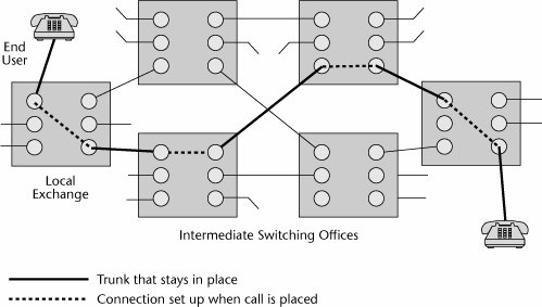
One of the key attributes of a circuit-switched connection is that it is a reserved network resource that is yours and only yours for the full duration of a conversation. But when that conversation is over, the connection is released. A circuit-switched environment requires that an end-to-end circuit be set up before a call can begin. A fixed share of network resources is reserved for the call, and no other call can use those resources until the original connection is closed. A call request signal must travel to the destination and be acknowledged before any transmission can actually begin. As Figure 3.1 illustrates, you can trace the path from one end of the call to the other end; that path does not vary for the full duration of the call, and the capacity provisioned on that path is yours and yours alone.
Figure 3.1. A circuit-switched call
Advantages and Disadvantages of Circuit Switching
Circuit switching uses many lines to economize on switching and routing computation. When a call is set up, a line is dedicated to it, so no further routing calculations are needed.
Since they were introduced in the mid-1980s, digital cross-connect systems (DCSs) have greatly eased the process of reconfiguring circuit-switched networks and responding to conditions such as congestion and failure. DCSs create predefined circuit capacity, and then voice switches are used to route calls over circuits set up by these DCSs. DCSs are analogous to the old patch panels. You may have seen a main distribution frame (MDF) on which twisted-pair wiring is terminated. The MDF is a manual patch panel, and before DCSs were introduced, when it was necessary to reconfigure a network based on outage, congestion, or customer demand as a result of shifting traffic patterns, technicians had to spend days or even weeks manually making changes at the MDF. The DCS is a software patch panel, and within the software are databases that define alternate routesalternate connections that can be activated if the network encounters a condition that requires some form of manipulation. DCSs are one of the elements of the PSTN that contribute to its reliability: When network conditions change, in a matter of minutes, a DCS can reconfigure the network around those changes. With such tools, the PSTN can offer five-nines reliabilityin other words, 99.999% guaranteed uptime. (DCSs are discussed in more detail in Chapter 4.)
Circuit switching offers the benefits of low latency and minimal delays because the routing calculation on the path is made only once, at the beginning of the call, and no more delays are incurred subsequently in calculating the next hop that should be taken. Traditionally, this was sometimes seen as a disadvantage because it meant that the circuits might not be used as efficiently as possible. Silence accounts for around half of most voice calls. Most people breathe and occasionally pause in their speech. So, when voice communications are conducted over a circuit that's being continuously held, and half the time nothing is being transmitted, the circuit is not being used very efficiently. But remember that this issue is important mainly when bandwidth is constrained. And as mentioned earlier in the book, bandwidth is growing at an astounding rate, through the widespread deployment of fiber optics, so the efficient use of circuits because of bandwidth constraints will not present the same sort of issue in the future that it once did. Hence, the low latencies or delays that circuit switching guarantees are more important than its potential drawbacks in bandwidth efficiency, and therefore, emerging models for optical networking use circuit switching in the core (see Chapter 11).
Circuit switching has been optimized for real-time voice traffic for which quality of service (QoS) is needed. Because it involves path calculation at the front end, you know how many switches and cables you're going to go through, so you can use a pricing mechanism based on distance and time. The more resources you use, either over time or over distance, the greater the cost. Again, developments in fiber economics are changing some of the old rules, and distance is no longer necessarily an added cost element. (QoS is discussed in more detail in Chapter 10, "Next-Generation Networks.")
Generations of Circuit Switches
Circuit switches have been around for quite some time. They have already been through three basic generations, and we're beginning to see a fourth generation.
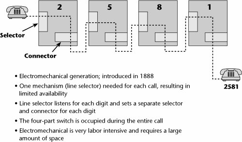
The first generation of circuit switches was introduced in 1888. It was referred to as the step relay switch, the step-by-step switch, or the Strowger switch, in honor of the man who invented it (see Figure 3.2).
Figure 3.2. A step relay switch
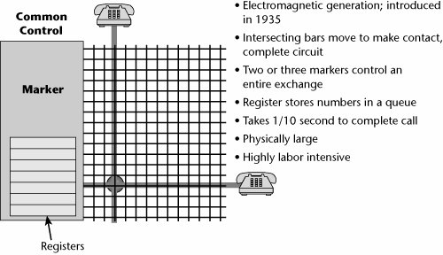
In 1935 the second generation of circuit switches was introduced: crossbar switches (see Figure 3.3). Crossbar switches were electromechanical, but each one could service a larger number of subscribers than could a step relay switch. Both step relay and crossbar switches still exist in the world. Of course, they are generally in underdeveloped areas, but they're not all relegated to museums quite yet. Every year you hear about one or two being decommissioned somewhere in the world.
Figure 3.3. A crossbar switch
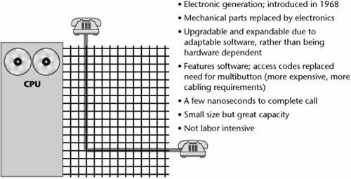
The third generation of circuit switchesstored program control (also referred to as electronic common control)was introduced in 1968. A stored program control is a computer-driven software-controlled switch (and it was for this purpose that the UNIX operating system was originally developed). Because this type of switch is electronic, there are no moving parts, and the switch has a longer life than earlier generations of switches. Because it is software controlled, it offers more guarantees against obsolescence, easier upgradability to enhanced feature sets, and better control over user features and cost features because everything can be programmed into databases that facilitate the call control process (see Figure 3.4).
Figure 3.4. A stored program control
The three generations of circuit switches are in place and operating at various levels of activity. Each new generation of switches has brought with it more connection-oriented features, features that help in making connections (e.g., customer features such as call forwarding and call waiting). Circuit switches in the future will likely be able to define connections based on a requested service class. Examples of variables that define a service class are the amount of delay that can be tolerated end to end, as well as between components, and the maximum loss that can be tolerated before the transmission is greatly hampered. Hence, we will be able to build connections to meet a particular service class and thereby aid in ensuring the proper performance of an application.
Customer premises equipment (CPE) circuit switches include PBXs. In the PSTN, circuit switches include the local exchanges with which subscribers access the network, the tandem or junction switches that interconnect numbers of local exchanges throughout a metro area, the toll or transit switches used for national long-distance communications, and the international gateways used for cross-country communications. A large number of vendors sell these circuit switches, as well as more specialized niche products.
A fourth generation of switchesoptical networking switchesis emerging now (see Chapter 12, "Broadband Access Alternatives"). Often, these optical networking elements are referred to as wavelength routers or optical switches. The idea is to be able to provision a very high-speed path, at OC-48 (i.e., 2.5Gbps), end to end across a network of dense wavelength division multiplexers. This will be increasingly important in providing communications interfaces to the high-speed switches that have become available.
With circuit switches, the ratio of performance to cost doubles approximately every 80 months to 40 months (i.e., normally the performance improves every 80 months, although sometimes new generations are created more rapidlyevery 40 months). Major architectural changes in circuit switches occur relatively infrequently.
Network switches are responsible for doing all the work of setting up and tearing down calls, as well as for addressing and providing the features requested. They provide a very high level of functionality on a very centralized basis within the network, and that enables the end stations to be very cheap and very dumb (e.g., a single-line telephone). Again, when intelligence was extremely expensive, there was something to be gained by centralizing it in a monolithic switch because that allowed consumers to access the network and to participate as users with a very low entry point. Until recently, if you wanted to spend time on the Internet, you had to have a PC, and a PC costs considerably more than a single-line telephone. On the other hand, costs are dropping in electronics and appliances all the time, so this is also becoming less of an issue, and perhaps in this way, too, distributing intelligence makes sense. This is the age-old argument about smart core/dumb edge versus dumb core/smart edge, and it speaks to the differences in philosophies between classic telecommunications engineers (affectionately referred to as "bell heads") and modern-day data communications engineers ("net heads"). The seminal paper that gave rise to this argument, "The Rise of the Stupid Network," is an excellent resource and can be found at www.isen.com/stupid.html. Chapter 10 talks more about the evolution of the intelligent edge.
Packet Switching
Whereas circuit switching was invented to facilitate voice telephony, packet switching has its origin in data communications. In fact, packet switching was developed specifically as a solution for the communications implications of a form of data processing called interactive processing.
The first generation of data processing was batch processing, in which a data entry clerk would sit down at a job entry terminal and key a volume of data onto some mediuminitially key punch cards, and later tape or disk. The data was then preaccumulated on an intermediate medium, and at some later point, a job would be scheduled and a link would be established to the host that would be responsible for processing the data. When this preaccumulated volume was transmitted, it was a steady stream of continuous high-volume data, so batch processing made quite effective use of a circuit-switched environment.
In contrast to batch processing, in interactive processing, data entry occurs online, so, in essence, data is transmitted only when you press the Enter key, but when you're looking at the screen or filling in a spreadsheet, nothing is being transmitted. Thus, interactive processing involves a traffic stream that's described as being bursty in nature, which implies long connect times but low data volumes. Therefore, interactive processing does not make efficient use of circuit-switched links: The connection would be established and held for a long period of time, with only little data passed. Packet switching was developed to increase the efficiencies associated with bursty transmission. Packet switching involves the multiplexing of multiple packets over one virtual circuit (i.e., the end-to-end logical connection that creates a complete path across the network from source to destination node; see Chapter 1, "Telecommunications Technology Fundamentals"). It also involves decentralizing the network intelligencenot only the intelligence for maintaining and tearing down the connections in centralized switches but also the endpoints that participate in the control of the end-to-end session.
Packets
A packet is basically a container for bits. We also use terms such as blocks, frames, cells, and datagrams to depict the same general concept, although there are differences in what type of information each contains. A packet can be a number of sizes, contain different numbers of bits, and have varying amounts of navigational control that the network nodes can use to navigate and route the packet. (Chapter 7 discusses some of the different types of packets and the techniques that use them.) In general, the features of a packet depend on several considerations. Each protocol, as it's developed over time, makes certain assumptions about whether bandwidth is available, or whether there's too much noise and therefore too much retransmission needed, or whether the key issue is latency. Packets of different sizes may therefore perform differently in different environments.
A packet is, in essence, a store-and-forward mechanism for transmitting information. Packets are forwarded through a series of packet switches, also known as routers, that ultimately lead to the destination. A packet header contains two very important pieces of information: the destination address and the sequence number. The original forms of packet switching (developed in the late 1960s and early 1970s) were connectionless infrastructures. In a connectionless environment, each packet is routed individually, and the packets might not all take the same path to the destination point, and hence they may arrive out of sequence. Therefore, the sequence number is very important; the terminating point needs it to be able to reassemble the message in its proper order.
Generally, in packet switching, packets from many different sources are statistically multiplexed and sent on to their destinations over virtual circuits. Multiple connections share transmission lines, which means the packet switches or routers must do many more routing calculations. Figure 3.5 illustrates a packet-switched network that uses virtual circuits. Packets are queued up at the various nodes, based on availability of the virtual circuits, and this queuing can impose delays.
Figure 3.5. A packet-switched network
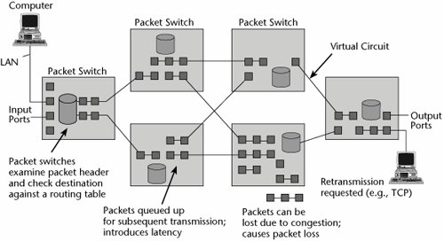
The first generation of packet-switched networks could support only data, not voice or video, because there was so much delay associated with those networks. As packet-switched environments evolve, we are developing techniques for separating and prioritizing the various traffic types. (Chapter 10 talks about these issues in depth.)
Connectionless Versus Connection-Oriented Packet-Switched Networks
There are two forms of packet-switched networks: connectionless and connection oriented.
Connectionless Packet-Switched Networks
You can picture connectionless networks by using a postal service analogy: Bob writes a letter, puts it in an envelope, and addresses the envelope. His carrier does not care in the least what it says on the envelope because she knows where she is taking that envelope. It's going to the next point of presence, which is the local post office. The local post office will be concerned with the destination zip code, but it doesn't care at all about the name or street address on the envelope. It simply wants to know what regional center to route it to. The regional center cares about the destination city, and the destination local post office cares about the actual street address because it needs to assign the letter to the right carrier. The carrier cares about the name so that the letter finds its way into the right mailbox. If the letter ends up in someone else's mailbox, the unintended recipient holds the ultimate responsibility for error control because he or she is the endpoint. In comparison, if Bob sends that letter via fax, it is connection-oriented: The connection to the destination address is established prior to transmission, and there are no intermediate stops.
A connectionless environment worries about getting a packet one step closer to the destination (see Figure 3.6). It doesn't worry about having an end-to-end view of the path over which the message will flow; this is the fundamental difference between connection-oriented and connectionless environments, and, hence, between infrastructures such as the PSTN and the Internet. Examples of connectionless packet-switched networks include the public Internet, private IP backbones or networks, Internet-based VPNs, and LANs. Again, each packet (referred to as a datagram transmission) is an independent unit that contains the source and destination addresses, which increases the overhead. That's one of the issues with connectionless packet-switched networks: If we have to address each packet, the overall percentage of control information relevant to the actual data being transported rises.
Figure 3.6. A connectionless network
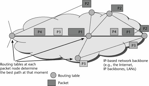
Each router performs a path calculation function independently, and each makes use of various routing protocols (e.g., OSPF, IS-IS, BGP). Each router calculates the appropriate next hop for each destination, which is generally based on the smallest number of hops (although some routing protocols use an abstract notion of cost, as defined by the network administrator, in making decisions). Packets are forwarded on a hop-by-hop basis rather than as part of an end-to-end connection. Each packet must be individually routed, which increases delays (due to queuing delays), and the more hops, the greater the delay. Therefore, connectionless environments provide less control over ensuring QoS because of unknown latencies, unknown retransmissions, and unknown sequences in which the packets will arrive.
Connection-Oriented Packet-Switched Networks
The connection-oriented packet-switched environment is something like a telephone network, in which a call setup is performed end to end. X.25, Frame Relay, ATM, and MPLS are all connection-oriented techniques. In a connection-oriented packet-switched network, only one call request packet contains the source and destination address (see Figure 3.7). Therefore, the subsequent packets don't have to contain the address information, which reduces the overall overhead. The call request packet establishes the virtual circuit. Each individual switch along each path, then, forwards traffic to the appropriate next switch until packets all arrive at the destination. With connection-oriented networks, each individual packet does not need to be routed. Instead, each packet is marked as belonging to some specific flow that identifies which virtual circuit it belongs to. Thus, the switch needs only to look at the mark and forward the packet to the correct interface because the flow is already set up in the switch's table. No repeated per-packet computation is required; consequently, connection-oriented networks reduce latencies, or delays.
Figure 3.7. A connection-oriented network
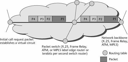
In the connection-oriented environment, the entry node contains the routing table, where the path is calculated and determined, and all packets follow that same path to the destination node, thereby offering a better guarantee of service.
Advantages and Disadvantages of Packet Switching
Packet-switching techniques have a number of limitations, including the following:
- Latencies occur because connection-oriented packet switching is a store-and-forward mechanism.
- Jitter occurs. Jitter refers to variable delay, to the delay in moving bits along the entire path, or, more specifically, to the variable arrival of packets. There are two main types of delay: jitter and entry-to-exit-point delay. Say that your end-to-end delay might meet the desired minimum of 150 milliseconds, but between switches 1 and 2, the delay is 20 milliseconds and between switches 2 and 3, it's 130 milliseconds. That variation will hamper some applications, so it needs to be controlled so that the network can support demanding applications.
- Packet loss occurs as congestion occurs at the packet switches or routers, and it can considerably degrade real-time applications. For example, if a few packets of a voice call are lost, you'll hear pops and clicks, but if the loss climbs into the 30% to 40% range, the voice might sound like "ye ah ng ng ah mm mm ah." This is the experience that some people today find at times when using the public Internet for telephony, where at peak periods of day, packet loss can be as great as 40%. But it is important to note that this varies greatly around the world; in some countries and locations, the loss is close to zero on the average, whereas other regions or providers may suffer double-digit packet loss during peak hours.
Given these drawbacks and the way packet-switched networks evolved, these networks originally gave no QoS guaranteesthey offered only best-effort QoS. But they guaranteed high reliability because you would be able to route packets through alternate nodes or pathways if they encountered link-resistant failures along the way; thus, you were guaranteed that information would be transported, but not within metrics such as latency and packet loss. Currently, protocols are being developed that will enable real-time applications such as voice, video, audio, and interactive multimedia to perform properly on packet-switched networks.
The pricing mechanism that evolved with packet-switched networks was a bit different from that used for circuit-switched networks. It was not based on time and distance but on usage: Billing is based on the volume of packets or the amount of bandwidth subscribed to. Distance insensitivity is a part of the packet-switched networking environment.
Generations of Packet Switches
Similar to circuit switches, packet switches have gone through several basic generations: X.25 switches (first generation), routers (second generation), Frame Relay and cell switches (third generation), and MPLS and tag-switched switches (fourth generation). Each generation of packet switching has increased the efficiency of packet processing and the speed of the interfaces it supports. In effect, the size of the pipes and the size of the interfaces dictate how effectively the packet-switched network performs. In packet switching, the processing is being pushed outside the network to the end nodes, so you need to have more intelligent software at the end nodes that get involved in the session setup, maintenance, and teardown, as well as flow control from end to end.
Besides X.25 switches, routers, and Frame Relay switches, packet switches include ATM switches and a new breed, called Tbps (terabits per second) switch routers. A large number of vendors sell these packet switches, and it seems that more companies jump on the bandwagon each day.
With packet switches, the ratio of performance to cost doubles every 20 to 10 months, so we see the evolution of new entries in the product line much more rapidly in this environment than in the circuit-switched world. However, again we rely on expensive end stationsPCs or other computersto finish the job of communication in packet switching. These end stations have to rely on protocols such as Transmission Control Protocol/Internet Protocol (TCP/IP), an open standard for internetworking that performs the equivalent of call setup/teardown and correct receipt of data. (TCP/IP is discussed in Chapter 8.) These end stations also have to ensure that all the data has been received and that it has been received correctly.
Comparing Circuit Switching and Packet Switching
What does the future hold for circuit switching and packet switching? Circuit switching is superior to packet switching in terms of eliminating queuing delays, which results in completely predictable latency and jitter in the backbone. Given the trend toward real-time visual and sensory communication streams, this seems to be the most important characteristic for us to strive toward. With the large capacities afforded by the new DWDM systems and other optical network elements, minimizing latency becomes more important than optimizing bandwidth via statistical multiplexing. (DWDM and other forms of multiplexing are discussed in Chapter 1.) We're likely to see the use of statistical multiplexing continue to increase at the edge and at the customer premises, as a means of economically integrating and aggregating traffic from the enterprise to present it over the access link to the network. In the core, fiber-based and circuit-switched networks are likely to prevail.
Table 3.1 briefly compares circuit switching and packet switching. As you look at the table, keep in mind that as we get more bandwidth, circuit-switched networks do not have to be so concerned with bandwidth efficiency. And as QoS is added to packet-switched networks, these networks are able to support real-time applications. Again, the prevailing conditions have a lot to do with what is best in a given network.
|
Characteristic |
Circuit Switching |
Packet Switching |
|---|---|---|
|
Origin |
Voice telephony |
Data networking |
|
Connectionless or connection oriented |
Connection oriented |
Both |
|
Key applications |
Real-time voice, streaming media, videoconferencing, video-on-demand, and other delay- and loss-sensitive traffic applications |
Bursty data traffic that has long connect times but low data volumes; applications that are delay and loss tolerant |
|
Latency/delay/jitter |
Low latency and minimal delays |
Subject to latency, delay, and jitter because of its store-and-forward nature |
|
Network intelligence |
Centralized |
Decentralized |
|
Bandwidth efficiency |
Low |
High |
|
Packet loss |
Low |
Low to high, depending on the network |
The PSTN Versus the Internet |
Part I: Communications Fundamentals
Telecommunications Technology Fundamentals
- Telecommunications Technology Fundamentals
- Transmission Lines
- Types of Network Connections
- The Electromagnetic Spectrum and Bandwidth
- Analog and Digital Transmission
- Multiplexing
- Political and Regulatory Forces in Telecommunications
Traditional Transmission Media
Establishing Communications Channels
- Establishing Communications Channels
- Establishing Connections: Networking Modes and Switching Modes
- The PSTN Versus the Internet
The PSTN
- The PSTN
- The PSTN Infrastructure
- The Transport Network Infrastructure
- Signaling Systems
- Intelligent Networks
- SS7 and Next-Generation Networks
Part II: Data Networking and the Internet
Data Communications Basics
- Data Communications Basics
- The Evolution of Data Communications
- Data Flow
- The OSI Reference Model and the TCP/IP Reference Model
Local Area Networking
Wide Area Networking
The Internet and IP Infrastructures
- The Internet and IP Infrastructures
- Internet Basics
- Internet Addressing and Address Resolution
- The Organization of the Internet
- IP QoS
- Whats Next on the Internet
Part III: The New Generation of Networks
IP Services
Next-Generation Networks
- Next-Generation Networks
- The Broadband Evolution
- Multimedia Networking Requirements
- The Broadband Infrastructure
- Next-Generation Networks and Convergence
- The Next-Generation Network Infrastructure
Optical Networking
- Optical Networking
- Optical Networking Today and Tomorrow
- End-to-End Optical Networking
- The Optical Edge
- The Optical Core: Overlay Versus Peer-to-Peer Networking Models
- The IP+Optical Control Plane
- The Migration to Optical Networking
Broadband Access Alternatives
- Broadband Access Alternatives
- Drivers of Broadband Access
- DSL Technology
- Cable TV Networks
- Fiber Solutions
- Wireless Broadband
- Broadband PLT
- HANs
Part IV: Wireless Communications
Wireless Communications Basics
- Wireless Communications Basics
- A Brief History of Wireless Telecommunications
- Wireless Communications Regulations Issues
- Wireless Impairments
- Antennas
- Wireless Bandwidth
- Wireless Signal Modulation
- Spectrum Utilization
Wireless WANs
- Wireless WANs
- 1G: Analog Transmission
- 2G: Digital Cellular Radio
- 5G: Enhanced Data Services
- 3G: Moving Toward Broadband Wireless
- Beyond 3G
- 4G: Wireless Broadband
- 5G: Intelligent Technologies
WMANs, WLANs, and WPANs
Emerging Wireless Applications
- Emerging Wireless Applications
- The Handset Revolution
- Mobile IP
- The IP Multimedia Subsystem
- Mobile Gaming
- Mobile Video
- Mobile TV
- Mobile Content
Glossary
EAN: 2147483647
Pages: 160
