The Next-Generation Network Infrastructure
The vision of next-generation networks originated in the Internet community over 20 years ago. The development and growth of packet-switching networks provided the basis for the concept of next-generation networks. The key principles defining this vision included connectionless datagram transport, best-effort packet delivery, and the separation of service creation from IP transport.
Today, virtually all service providers recognize the need to evolve their infrastructures to support multimedia and content delivery services. Telecommunications service providers, both wireline carriers and mobile operators, face the challenge of providing seamless migration of the circuit-switched voice services onto an IP-based backbone while retaining all the important traditional features, particularly those required by law. The key PSTN capabilities that must be preserved include public safety, law enforcement, fraud prevention, precedence and preemption of traffic during emergencies, assistance for the hearing and speech impaired, privacy and data protection, consumer protection against intrusion, and issues of billing and settlement. In addition, seamless interoperability is critical.
In response to this challenge, carriers and service providers, with the participation of vendors and governments, are working with an ITU study group on developing a new interpretation of the next-generation network. The main objective of these efforts is to ensure the integration and interoperability of IP networks with the PSTN and mobile networks. The ITU's next-generation network is a packet-based network capable of providing telecom services and making use of multiple broadband, QoS-enabled transport technologies in which service-related functions are independent of the underlying transport-related technologies. Furthermore, the ITU's vision encompasses the need to support generalized mobility while allowing consistent and ubiquitous provisioning of services to users. The objective of the ITU-defined next-generation network is to support much more than simple voice communications, including services such as presence management, instant messaging, push-to-talk, voicemail, video communications, and a wide range of multimedia applications, including both real-time and streaming modes.
Many industry observers believe the ITU next-generation network effort is an attempt by the ITU to take control of the Internet. Carriers and governments have the equally strong view that the Internet today is not serving the interests of consumers or businesses well. The current Internet world is plagued by infrastructure vulnerabilities as well as the rapidly growing problems of fraud, cybercrime, spamming, and phishing. This reality lends strength to the argument that there is a need for greater control by operators, and the ITU next-generation network standard could serve this purpose. On the other hand, it also suggests a highly controlled world, one many of us may not feel comfortable in. To be fair, there are potential evils of such control, including limited choices, a favoring of the wealthy, and reduced democracy, without a definite guarantee of any more security. There are arguments for both sides of the issue, and you need to be aware of them to ensure open discussion and a voice in the decisions that will ultimately be made.
In addition to gaining control, there are other potential benefits for carriers choosing to implement infrastructure based on the ITU next-generation network. Operators implementing that architecture will benefit from the QoS features inherent in next-generation networks and will therefore be positioned to give preferential treatment to their own multimedia services as well as have the opportunity to create walled gardens. In so doing, operators can reduce competition by virtue of mediating users' access to applications or content.
As discussed in the following sections, the evolving next-generation network infrastructure is composed of several key elements, including IMS, a new three-tiered architecture, a multiservice core, QoS, and an MPLS architecture.
The IP Multimedia Subsystem
The architecture of the ITU's next-generation network relies heavily on the IP Multimedia Subsystem (IMS) framework. Originally developed by the 3G Partnership Project (3GPP; www.3gpp.org) for 3G/UMTS networks, IMS was based on standards work that started in mid-1999 for an all-IP network. IMS has been extended to cover wireline networks as well, and it now facilitates FMC, eliminating the distinction between wired and wireless networks. (IMS for wireless networks is discussed in more detail in Chapter 16.) FMC speaks to the vision of being able to use one phone with one number, address book, and voicemail bank while enjoying the benefits of low-cost, high-speed connectivity in the office or fixed-line residential environmentof course, still enjoying the freedom of mobility in the WAN. Seamless handoff between fixed and mobile networks is also included.
Defined by 3GPP and 3GPP2 (www.3gpp2.org), IMS is a service infrastructure that relies on Session Initiation Protocol (SIP) to establish and maintain call control. IMS is an internationally recognized standard that defines a generic architecture for offering VoIP and other multimedia services in wireline and wireless applications. By adopting SIP as the signaling protocol, service providers have a standard that works well for both voice and data. In fact, VoIP has now become the foundation of almost every service provider's next-generation network architecture, including wireless, wireline, and cable/MSP operators. As we examine the role of VoIP in these providers' networks, it is clear that it constitutes a vital part of their strategies for differentiation, reduced costs, and increased competitiveness.
IMS gives carriers the opportunity to build a single and common IP service infrastructure independent of the access method. Building the infrastructure only once causes the cost per service to go down over time and increases the opportunity to offer a more integrated, richer, and more seamless environment. The IMS architecture offers a number of benefits, including enhanced person-to-person communications; improved interaction between media streams, which enables easy integration and interworking of different IP-based services; improved service mobility, which enables services to be offered over various access networks; and the ability of third-party developers and vendors to easily create and integrate new solutions through well-defined APIs and standards.
IMS applications include voice telephony, video telephony, multimedia streaming, HTTP and TCP/IP browsing, instant messaging, file sharing, gaming, push-to-talk/push-to-media, and presence-based services. Major vendors, including Ericsson, Lucent, Nortel, and Siemens, have made substantial investments in IMS software.
Four basic principles are associated with IMS:
- Access independence As the name implies, access independence means that IMS is intended to enable work with any networkbe it fixed, wireless, or mobileand includes all the access options, such as UMTS, GPRS, CDMA2000, WLAN, WiMax, DSL, and cable. Gateways are used to accommodate older systems such as circuit-switched telephone networks and GSM cellular systems. The fact that open interfaces are used between the control and service layers (discussed later in this chapter) allows the elements and sessions from various access networks to be combined.
- Different network architectures IMS allows service providers and carriers to employ a variety of underlying network architectures.
- Terminal and user mobility Terminal mobility is supported by roaming via the mobile network, and user mobility is enabled via IMS and SIP.
- Extensive IP-based services Supporting a wide range of IP services is the ultimate goal, and IMS can enable support of applications ranging from VoIP to Push-to-Talk over Cellular (PoC), messaging, presence management, multiparty gaming, and content sharing.
IMS Protocols
IMS creates a telephony-oriented signaling network that overlays an underlying IP network. IMS uses Session Initiation Protocol (SIP), with specific extensions for IMS. As discussed in Chapter 9, SIP is a peer-to-peer protocol in which end devices, known as user agents, initiate sessions. It is an end-to-end signaling protocol, which means that all the logic is stored in end devices, except the routing of SIP messages. State is also stored in end devices only; there is no single point of failure, and networks designed this way scale well. An IMS network comprises many SIP proxy servers that mediate all customer/user connections and access to network resources. The tradeoff for the distributiveness and scalability is higher message overhead because the messages are sent end to end. The aim of SIP is to provide the same functionality as the traditional PSTN, but because of their end-to-end design, SIP networks are much more powerful and open to the implementation of new services.
Although IMS is SIP based, it includes enhancements and exceptions to the SIP specification, particularly for registration, authentication, and session policy. IMS uses DIAMETER rather than RADIUS for authentication, taking advantage of DIAMETER's additional support for charging and billing functions, such as prepaid calling services. IMS also uses the Common Open Policy Service (COPS) protocol for mobile operators to enforce security and QoS policies across network elements.
IMS initially required the use of IPv6 (discussed in Chapter 8), but given the number of transport networks using IPv4, this requirement has been relaxed. IMS terminal devices are centrally and tightly controlled, unlike the IP networks that provide the underlying network transport for IMS.
IMS assumes that each user is associated with a home network, and it supports the concept of roaming across other wired or wireless networks. Network services and applications are implemented in the user's home network. Because visited networks act primarily as vehicles for multimedia IP packets sent or received by the roamer, service knowledge is not required in visited networks. IMS also includes a policy engine and an authentication, authorization, and accounting (AAA) server for operator control and security.
The IMS Architecture
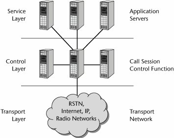
The IMS standard defines a generic architecture that offers VoIP and other multimedia services within wireline and wireless infrastructures. As shown in Figure 10.2, the IMS architecture is divided into three layers: service (or application), control, and transport (or access).
Figure 10.2. The IMS layers
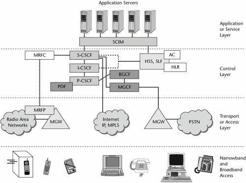
The IMS architecture consists of various components, including SIP proxies, media gateways, and various types of servers. The key components, as shown in Figure 10.3, include the following:
- Service- or application-layer components:
- Application servers Application servers are IMS-compliant multimedia application servers. The application server can provide service capability interaction manager (SCIM) functions to manage interactions.
- Control-layer components:
- Call session controller function The call session controller function (CSCF) provides call control similar to that of a VoIP softswitch. There are three types of CSCFs: the proxy CSCF (P-CSCF), which is a SIP proxy that provides subscriber access to network-based services and sits in front of the serving CSCF; the serving CSCF (S-CSCF), which is the primary call controller for the operator network; and the interrogating CSCF (I-CSCF), which is a SIP proxy that can be optionally used by a network operator to hide internal configurations.
- Home subscriber servers (HSSs) An HSS handles centralized provisioning, management, and authentication/authorization. CSCFs consult with the HSS before initiating SIP connections. The HSS includes the home location register (HLR) and the authentication center (AC). The HLR is a database used for storage and management of subscriptions; storage of permanent information about subscribers, including the subscriber's service profile; location information; and activity status. The AC is used to protect subscribers from unauthorized access (by providing authentication and encryption parameters that verify the user's identity) and to ensure the confidentiality of each call. It also protects network operators from different types of fraud found in today's mobile networks.
- Subscription locator function (SLF) The SLF locates the database that contains subscriber data in response to queries from the I-CSCF or application server.
- Policy controllers A policy controller is a server that performs the policy decision function (PDF) for QoS and security. It checks the HSS database and uses COPS to control policy enforcement points embedded in other network elements.
- Border gateway control function (BGCF) The BGCF handles control/signaling messages to other IMS domains.
- Multimedia resource function controller (MRFC) The MRFC interprets information coming from an application server and S-CSCF and controls the multimedia resource function processor (MRFP) accordingly. It also generates CDRs.
- Multimedia gateway controller function (MGCF) The MGCF, also known as a softswitch or call agent, communicates with the CSCF and controls the connections for media channels in an IMS media gateway. The MGCF performs protocol conversion between ISUP (ISDN, User Part) and the IMS call control protocols. (ISUP is a part of SS7 that is used to set up calls in the PSTN.)
- Transport- or access-layer components:
- Multimedia resource function processor (MRFP) The MRFP provides a wide range of functions for multimedia resources, including provision of resources to be controlled by the MRFC, mixing of incoming media streams, sourcing media streams (for multimedia announcements), and processing of media streams.
- Media gateway (MGW) The MGW functions as a translation device between different networks (e.g., by performing the conversions between VoIP and TDM-based voice on the PSTN). A related signaling gateway (SGW) may be included for exchanging control messages with the PSTN's SS7 control network. MGWs are controlled by the MGCF, and they communicate with one another using protocols such as MGCP or Megaco.
Figure 10.3. The IMS architecture
The History and Future of IMS
The base IMS functionality was first defined in the 3GPP Release 5 (R5) standards, finalized in March 2003. This standard was optimized for use by GSM UMTS wireless networks.
The second phase of IMS standards development ended in September 2004 with the publication of 3GPP Release 6 (R6) standards. R6 adds support for SIP forking and multiway conferencing and the group management capabilities necessary for instant messaging and presence services. R6 also allows for interoperability between the IMS variant of SIP and the IETF SIP standard (RFC 3261). Finally, R6 adds interworking with WLANs.
3GPP Release 7 (R7), working together with TISPAN (Telecoms and Internet converged Services & Protocols for Advanced Networks) R1, adds support for fixed networks. TISPAN is a standardization body of ETSI that specializes in fixed network and Internet convergence. The TISPAN architecture is based on the concept of cooperating subsystems sharing common components.
IMS products began to be introduced in 2005, and IMS-based consumer and entertainment services are expected in 2006 or 2007. One of the first applications to use IMS is likely to be Push-to-Talk over Cellular. (Push-to-talk is discussed in Chapter 16.)
The Next-Generation Network Architecture
Network architectures are in transition. In today's environment, time division and statistical multiplexers gather customer traffic for additional circuit-based aggregation through a stable hierarchy of edge (i.e., local), tandem, and core switching offices in the carrier networks. Overlay networks, such as X.25, Frame Relay, ATM, and the Internet, have been put in place and have created the need to internetwork services, thereby eroding traditional network borders. As additional access in transport optionsincluding cable, DSL, fiber, and wirelessbegan to be introduced, they joined traditional modems and brought their own high-density access aggregation devices into the picture. Meanwhile, in the core, SDH/SONET transport has been layered over DWDM, adding capacity and producing a variety of vendor-specific switching, routing, and management options.
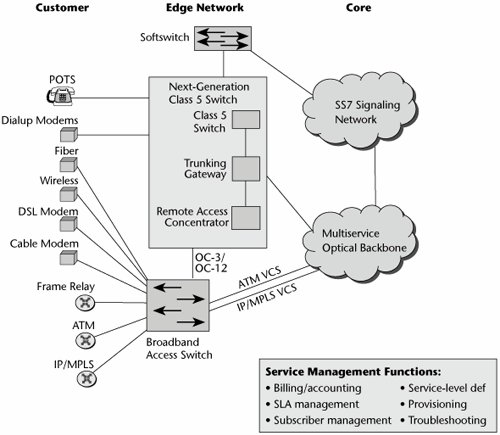
Figure 10.4 puts today's networks into a visual context. Residential customers on POTS connect through their first point of access, the Class 5 (i.e., local exchange) switch. Some users are serviced by xDSL, and these lines terminate on a DSL access multiplexer (DSLAM). The DSLAM links back to the local exchange for regular voice traffic, which is diverted out over the PSTN, and it also has connections into the packet-based backbone (which could be a core or backbone network based on IP, ATM, Frame Relay, or MPLS) for data traffic.
Figure 10.4. Today's networks
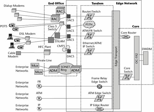
Some users have dialup modems that terminate on remote access devices; through digital access cross-connects and routers, they use private lines to access their corporate facilities to work with internal LANs and resources. Customers who have optical networks have a series of multiplexers onsite that multiplex suboptical carrier levels up to levels that can be introduced into an SDH/SONET add/drop multiplexer to carry that traffic through the SDH/SONET ring, or today they may even have connections directly into DWDM systems. Customers also have Frame Relay, ATM, and IP switches and routers that interface into complementary equipment within the carrier network. Between the access and the edge is a plethora of different equipment, requiring different interfaces; different provisioning, billing, and network management systems; and different personnel to handle customer service and technical support and maintenance.
The core network is increasingly becoming optical. Therefore, there is access into the high-speed optical multiplexers via routers or switches, and then those optical carrier levels in the SDH/SONET hierarchy are further multiplexed via DWDM systems to take advantage of the inherent bandwidth available in those fibers.
The broadband architecture is an increasingly complicated arena. Many different alternatives in the network have been engineered to support specific voice, data, or video applications, meeting certain performance characteristics and cost characteristics. When we add up all the different platforms and networks we have, it's quite a costly environment and one that is difficult to maintain and manage cohesively. By building the overlay networks and separating access and transport functions, carriers manage to add capacity and new services without interrupting their existing services. However, the downside of this system is that the new services rarely use the same provisioning management and troubleshooting systems as the old network. These operations and management costs can amount to as much as half of the carrier's total cost to provide a service.
The Three-Tiered Architecture
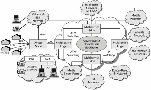
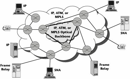
The broadband architecture has three tiers. The first tier involves the access switches; it is the outer tier, associated with delivering broadband to a customer. The second tier involves the edge switches and is associated with protocol and data service integration. The third tier, the inner tier, involves the core switches and handles transmission of high-speed packet data throughout the backbone. Figure 10.5 shows the components that comprise these three tiers, and the following sections describe them.
Figure 10.5. A multiservice network
The Outer Tier: The Broadband Access Tier
Access tier devices include legacy network infrastructure devices such as Class 5 local exchanges and digital loop carriers. The access tier also includes DSLAMs, which are designed to concentrate hundreds of DSL access lines onto ATM or IP trunks and then route them to routers or multiservice edge switches.
Also in the access environment are IADs, which provide a point of integration at the customer edge, integrating voice, data, and video networks and supporting broadband access options. The access tier also contains remote access servers, which typically provide access to remote users via analog modem or ISDN connections and include dialup protocols and access control or authentication schemes. Remote access routers are used to connect remote sites via private lines or public carriers, and they provide protocol conversations between the LAN and the WAN.
The Middle Tier: The Intelligent Edge
The second tier involves the intelligent edge devices. These can include next-generation switches, VoIP gateways, media gateways, trunking gateways, ATM switches, IP routers, IP switches, multiservice agnostic platforms, optical networking equipment, and collaborating servers. This tier is also home to the network management stations that manage all those devices.
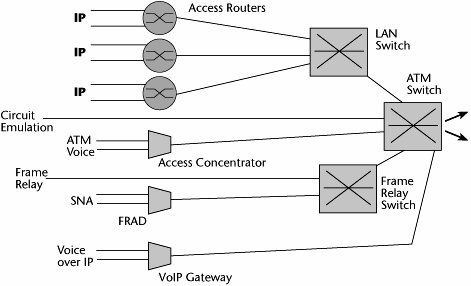
The edge devices and the intelligent edge generally handle AAA functions. They identify the specific levels of performance required and map the proper QoS levels into the packet according to the backbone protocol. The intelligence keeps moving closer and closer to the customer, and it is actually being extended to CPE. We're trying to get away from an environment that has a lot of single-purpose networks associated with single-purpose boxes and their own individual access lines (see Figure 10.6). As mentioned previously, there are complexities involved with acquisition, with ongoing maintenance, and with the talent pool to administer and maintain these systems.
Figure 10.6. Complexities with single-purpose boxes
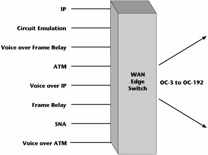
The ideal situation would be a multipurpose WAN switch that could facilitate the termination of any type of data protocol as well as facilitate aggregation at high speeds to the various optical levels (see Figure 10.7). This is what we're striving for with the intelligent edge.
Figure 10.7. Simplicity with multipurpose switches
Traditionally, networks have employed two types of devices at the edge:
- Access-oriented devices These devices include MSPPs, which can handle all the popular data protocols and interfaces, except that not all of them are designed to be optical aggregators.
- Transport-oriented devices These optical aggregations systems support a full range of hierarchical aggregation, from DS-3 to OC-192. They offer electrical-to-optical conversion as well. But they don't offer all the data interfaces.
Successful edge devices need to handle multiprotocol data services as well as multispeed aggregation. Emerging solutions for the intelligent network edge therefore have to meet four critical objectives. First, there's a need to bridge the bandwidth bottleneck that currently exists between user LANs and the optical core. We have LANs that operate at 1Gbps (Gigabit Ethernet, or GigE) and even 10Gbps (10 Gigabit Ethernet, or 10GigE), and 100Gbps Ethernet is in development. We have optical cores that operate at 10Gbps (OC-192) and are moving beyond that, to 40Gbps (OC-768), with some hoping to introduce even 80Gbps. By applying multiple wavelengths in a fiber, we can achieve terabits per second. But the WAN link between the LAN and the optical core is still often limited to a link that can handle only 56Kbps to 2Mbps. So a severe bottleneck is occurring at the LAN/WAN integration point, and that needs to be addressed. Second, we need to improve the serviceability of the carrier networks; we need to make it easier to define, provision, bill, and manage services and equipment across a converged area. Third, we need to enable converged carrier infrastructures to simplify the carrier networks and to simplify the support of end-user services. Fourth, having multiple options for broadband access brings with it the challenge and complication of supporting multiple access techniques. Therefore, we must provide media-agnostic service interworking between multiple access technologies at the edge. The intelligent edge must be able to support each converged service, recognizing and properly handling all the voice, data, video, and multimedia traffic.
New network designs are promising to facilitate a number of issuesabove all to eliminate all the service-specific and hierarchical aggregation layers that reside in today's edge network. All those layers contribute to cost and complexity over time. Figure 10.8 depicts what the next-generation access edge might look like. You can see that we've replaced separate platforms throughout the edge with more integrated environments; for example, we might have softswitches that enable traditional PSTN call telephony-type features, but over packet backbones. Circuit switches are predicted to continue to be present in the network for another 10 to 20 years, depending on location. Trunking gateways are used to attach multiple media gateways that are putting voice into IP packets to the underlying SS7 network. Remote access concentrators enable remote access for telecommuters and people who need to access remote corporate hosts. New generations of broadband access switches enable the multialternative broadband access environmentcable modems, Frame Relay, xDSL, wireless alternatives, and so on. We want to reduce the edge environment to a simpler set of agnostic, multiplatform, multiprotocol intelligent edge devices.
Figure 10.8. The next-generation network edge
The main responsibilities of the intelligent edge include broadband access, adaptation of the native traffic to the underlying backbone technique, and concentration of many customer streams onto the bigger pipes within the core. This is the point at which the service attributes are mapped to QoS mechanisms in order to deliver the requested performance and thereby live up to the SLAs. One of the major benefits is that it allows rapid and dynamic service provisioning, and it even allows customization for individual users. These service changes can be made without affecting the core, so as new service logic is required and as market segments find demand for new services, we will not necessarily have to reengineer the entire core network to accommodate those changes. Service provisioning is therefore decoupled from service specification and service delivery.
The Inner Tier: The High-Speed Core
The access and edge switches are designed to be scalable, both in port counts and in their ability to deliver multiservice support, and they are evolving to include more and more intelligence and features that would enable policy-based service management. In contrast, core switches are designed to be incredibly big and incredibly fast but generally quite dumb. Their main objective is to transport traffic as reliably and quickly as possible, at the highest available rate.
So in the emerging environment, we see a reversal. In the traditional PSTN, the edges served the network core, and the network core had all the intelligence. Now, the network core is serving the edges, and intelligence is being distributed closer and closer to the customer premises (see Figure 10.9).
Figure 10.9. The network core serving the edges
The Multiservice Intelligent Edge
As discussed in the preceding section, the evolution of a multiservice intelligent edge is a key element of the next-generation infrastructure. Service providers face the challenge of supporting their existing data services while transitioning to a new IP world. They need a service edge platform that will allow them to achieve this goal. Multiservice switches can now support Layer 3 services while continuing to support traditional Layer 2 ATM and Frame Relay services, DSL aggregation, and voice and wireless applications. They also support Packet over SDH/SONET (PoS) and Ethernet interfaces, as well as interfaces for Frame Relay, ATM, Circuit Emulation Service, and TDM.
Most of today's Tier 1 service providers have ATM-based networks that support Frame Relay, ATM, and private-line services. These services continue to show growth. For example, IP traffic growth in the United States is expected to be approximately 75%, while non-IP data is expected to grow at approximately 40%. Service providers are looking for new IP and Ethernet revenue streams while continuing to support and grow their current private-line, Frame Relay, and ATM services. However, service providers don't know how the service mix will change over time and therefore need the flexibility to manage changing demand.
An additional complication comes from the fact that while non-IP data represents a decreasing percentage of traffic, the revenues associated with these services remain significantly higher than those for IP. Revenues for IP are expected to be only 5% of total Frame Relay and ATM revenues. (But bear in mind that customers are used to paying more for Frame Relay and ATM data services, and of course the service providers are more than happy to maintain the status quo.)
The trend is to accommodate a full mix of services. Service providers will use a combination of Layer 2 and Layer 3 networks to deliver new services, and the choice will depend on many variables. Proper components, including service routers and routing switches, are necessary to migrate existing networks. Servicing this market completely requires an end-to-end approach that includes components, interworking, and end-to-end management.
Attributes of the Multiservice Edge
The multiservice edge has the following attributes:
- Support for traditional and emerging Layer 2 and Layer 3 services These services include IP VPNs, broadband remote access servers, Internet access, Virtual Private LAN Services (VPLS), virtual private wire service (VPWS), ATM, Frame Relay, and security services. The multiservice edge is required to support today's revenue streams and emerging services over a cost-reduced infrastructure.
- High reliability The multiservice edge must support true carrier-grade reliability at the nodal, network, and service levels to provide high service availability and support mission-critical, converged voice, video, and data traffic.
- A modular, flexible hardware and software architecture The multiservice edge must have distributed input/output, and it needs a control and data plane that has the ability to independently scale switching capacity and the control plane. This is required to enable pay-as-you-grow deployment in any size POP, flexible sparing (or backup) strategies, and performance improvements. Multiservice optimized traffic management must have very granular integrated Layer 2/Layer 3 traffic management that is consistent across all media and services. This is required to enable differentiated services through service bundling and unique SLAs.
- Intelligent integration into the existing architecture The multiservice edge must provide interworking with existing platforms, management systems, and operational support systems, and it must support current SLAs and service definitions.
Service and Protocol Integration at the Intelligent Edge
Multiservice edge platforms are a new category of product designed to deliver convergence, revenue generation, and cost reductions on a single edge device. The multiservice edge is an emerging market segment of edge devices optimized for converging Layer 2/Layer 3 services over IP/MPLS.
A multiservice edge device must be designed from inception for full multiservice convergence. This includes the requirement to deliver high reliability, provide a modular and flexible architecture, enable multiservice optimized traffic management, and support intelligent integration into existing infrastructures. The multiservice edge involves two key components: routing switches, which perform full routing and switching and offer scalability and full IP functionality distributed to the line cards, and service routers, which perform full Internet routing with the mechanisms to enforce VPNs based on SLAs.
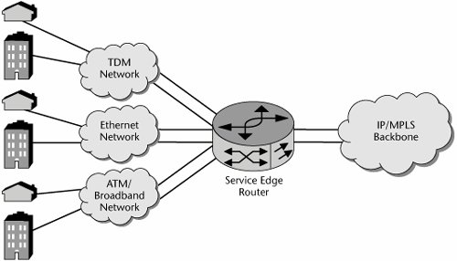
Service edge router requirements include combining routed and switched data services, particularly because new services do not necessarily replace old services. Another requirement is an interface to TDM and packet access networks (see Figure 10.10). Again, access networks are not readily replaced. The service edge router must adapt multiple services for delivery across a common packet core, with the core being transparent to the customer, and it is a key point for mapping services into network QoS. Finally, it must manage a large number of customer interfaces, both physical and logical.
Figure 10.10. The multiservice edge
Service providers also want to allow their customers to determine the rate at which they move from Frame Relay and ATM to IP/MPLS. Ideally, service providers would like to allow their customers to use any access method they want and operate as a single VPN. This means enterprise customers could keep low-speed Frame Relay at some sites while upgrading other sites to Ethernet services. For the service providers, this means the potential for better service margins, greater customer retention, and the potential to increase the share of enterprise spending by bringing additional locations into the VPN service.
The multiservice edge must support mission-critical applications. As the IP network moves from a best-effort network to one that supports more mission-critical business applications and real-time consumer and business applications, the requirements for edge equipment change. Today, applications such as gaming, streaming media, and VoIP represent only a small percentage of U.S. IP traffic, but it is expected that the volume will grow as IP networks add the requisite QoS and high-availability capabilities.
While these mission-critical applications allow service providers to increase the revenues from their IP networks, they also demand a higher level of service reliability. The gradual migration to voice-over-packet also introduces the requirement for stringent QoS, further emphasizing the need to provide the predictability and control that TDM networks offer. Five-nines reliability (i.e., 99.999%, or less than 5 minutes of downtime per year) will become an increasingly critical component of IP networks.
The Architecture of the Multiservice Edge
The multiservice edge has three main architectural requirements:
- High reliability We can address the need for reliability by providing for built-in redundancy in the form of redundant switch fabrics and components, stable software that offers five-nines reliability, support for in-service upgrades, and the ability to easily integrate into the service provider's operational support systems. In the realm of availability, the ability to perform hitless software upgrades is a necessity, as are hot-swappable components and modules. Modular software code is required for maximum flexibility. Finally, the ability to detect failures and reroute traffic while detecting and reporting faults is required.
- Scalability The multiservice edge must support increasing amounts of traffic, increasing numbers of users, and the ability to add capacity as needed.
- Flexibility The multiservice edge must be able to handle any protocol type with equal ease, to upgrade software seamlessly, and to support a wide and diverse range of interfaces.
A multiservice network is a single network solution that delivers common services end to end. It is a fully managed solution that provides interworking and native services as well as best-of-breed routing switches and service routers.
The multiservice edge also involves feature requirements such as the following (see Figure 10.11):
- Multiservice support The multiservice edge must support Frame Relay, ATM, IP, and MPLS services.
- Support for multiple standards The multiservice edge must support multiple standards, including ATM's User-to-Network Interface (UNI), the Private Network-to-Network Interface (PNNI), Border Gateway Protocol (BGP), Intermediate System to Intermediate System (IS-IS), and Open Shortest Path First (OSPF), as well as VPN standards such as RFC 2547 and pseudo-wire emulation edge to edge, along with interworking standards for Frame Relay and ATM.
- Support for a wide variety of interfaces The multiservice edge must support various protocols, such as Frame Relay, ATM, GigE, and PoS.
- Support for both network and service interworking The multiservice edge must support both network and service interworking. Multiservice switches support interworking of Frame Relay and ATM services today. Multiservice edge devices must also support network interworking, such as the ATMMPLS network interworking specification, allowing them to act as gateways between Layer 2 and Layer 3 networks. (For detailed information and updates on the various service and network interworking specifications available for Frame Relay, ATM, and MPLS, consult the MFA Forum site, at www.mfaforum.org.)
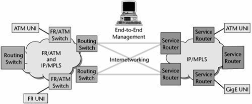
Figure 10.11. Migrating to a multiservice network
Quality of Service
As mentioned throughout this chapter and others, QoS issues play a very important role in next-generation networks. It is becoming increasingly important to provide for very granulated levels of service, thereby allowing very high performance and at the same time creating platforms for multitudes of new revenue-generating services.
QoS is the ability to provide different levels of service to differently characterize traffic or traffic flows. It constitutes the basis for offering various classes of service to different applications or segments of end users. This then allows the creation of different pricing tiers that correspond to the different CoS and QoS levels. QoS is essential to the deployment of real-time traffic, such as voice or video services, as well as to the deployment of tiered data services.
QoS includes definitions of the network bandwidth requirements, the user priority control, control of packet or cell loss, and control of delayboth transit delay (which is end to end) and traffic delay variations (i.e., jitter). Traffic characterizations include definitions of the delay tolerance and elasticity for that application. They can also associate delay tolerance and elasticity with applications and users and potentially even time-of-day, day-of-week scenarios. It is necessary to be able to ensure various levels of service; the availability of bandwidth, end-to-end delay, delay variances, and packet losses that support the application in question; and the relative priority of traffic. Also, QoS is associated with policy admission control and policing of traffic streams.
There are two ways of implementing QoS. Implicit QoS means that the application chooses the required QoS. Explicit QoS means that the network manager controls that decision.
There are three main approaches to QoS. The first is an architected approach, and ATM falls under this category. The second is per-flow services, where the QoS is administered per flow, or per session. This includes the reservation protocol (Resource Reservation Protocol [RSVP]) that is part of the IETF IntServ specification, as well as MPLS. The third approach is packet labeling, in which each individual packet is labeled with an appropriate QoS or priority mark; the techniques that use this approach include IEEE 802.1p and 802.1pq, as well as the IETF DiffServ specification.
The following sections describe various QoS tactics, including ATM QoS, IP QoS, and Class-Based Queuing (CBQ), as well as policy-based management and related protocols, such as COPS and Lightweight Directory Access Protocol (LDAP).
ATM QoS
ATM QoS includes four different service levels (one of which has two variations) that define a series of specific QoS parameters that tailor cells to fit video, data, voice, or mixed-media traffic. The following are the four service classes:
- Constant bit rate (CBR) CBR provides a constant, guaranteed rate to real-time applications such as streaming videoso it is continuous bandwidth. It emulates a circuit-switched approach and is associated with minimum latencies and losses. CBR is the highest QoS you can get, and it is for very demanding applications, such as live media, streaming media, streaming audio, streaming video, and VOD. Initially, CBR was to be used for applications such as voice and videoconferencing, but we have found that those applications do not necessarily need the continuous bandwidth. As mentioned previously, much of a voice conversation is silence. If we were carrying that voice over CBR service, whenever there was silence, the ATM switches would be stuffing in empty cells to maintain that continuous bandwidth, and of course that would be overkill and a waste of network resources.
- Variable bit rate (VBR) VBR has two subsets: real-time (VBR-RT) and non-real-time (VBR-NRT). VBR provides a fair share of available bandwidth according to a specific allocation policy, so it has a maximum tolerance for latencies and losses. VBR is the highest QoS in the data realm, and it is also an adequate QoS for real-time voice. VBR-RT can be used by native ATM voice with bandwidth compression and silence suppression. So when somebody is silent, VBR-RT makes use of the available bandwidth to carry somebody else's cells, and therefore, VBR is also appropriate for multimedia functions such as videoconferencing. VBR-NRT can be used for data transfer where response time is critical (e.g., transaction-processing applications such as airline reservations, banking transactions).
- Available bit rate (ABR) ABR supports VBR data traffic with average and peak traffic parameters (e.g., LAN interconnection and internetworking services, LAN emulation, critical data transfer that requires service guarantees). Remote procedure calls, distributed file services, and computer process swapping and paging are examples of applications that would be appropriate for ABR.
- Unspecified bit rate (UBR) You could call UBR poor-man's ATM. It provides best-effort service. UBR offers no service guarantee, so it is used for text data and image transfer, messaging, and distribution of noncritical information, where there is no need for a set response time or service guarantee.
ATM provides a very well-planned approach to providing QoS. Table 10.3 shows how each service class allows you to define or not define certain parameters. The parameters boil down to two major categories:
- QoS parameters These parameters include cell error rate (CER; the percentage of errored cells), cell loss ratio (CLR; the percentage of lost cells), cell transfer delay (CTD; the delay between the network entry and exit points), cell delay variation (CDV; the jitter), and cell misinsertion rate (CMR; the number of cells inserted on the wrong connection).
- Traffic parameters These parameters include peak cell rate (PCR; allows you to specify the maximum amount of bandwidth allowed on a connection), sustainable cell rate (SCR; allows you to specify guaranteed bandwidth during the variable transmissionsused only by VBR), maximum burst size (MBS; allows you to specify the maximum number of cells that will be transmitted at PCRused only by VBR), cell delay variation tolerance (CDVT; allows you to specify the maximum allowable jitter), minimum cell rate (MCR; allows you to specify the rate in cells per second that the source can transmitused only in ABR), and allowed cell rate (ACR; works with ABR's feedback mechanism that determines cell rate).
As Table 10.3 shows, UBR allows you to define very little, whereas CBR allows you to tightly control most of these parameters.
|
Parameter |
CBR |
VBR-NRT |
VBR-RT |
ABR |
UBR |
|---|---|---|---|---|---|
|
Cell loss ratio |
Yes |
Yes |
Yes |
No |
No |
|
Cell transfer delay |
Yes |
Yes |
Yes |
No |
No |
|
Cell delay variation |
Yes |
Yes |
Yes |
No |
No |
|
Peak cell rate |
Yes |
Yes |
Yes |
Yes |
Yes |
|
Sustained cell rate |
No |
Yes |
Yes |
No |
No |
|
Minimum cell rate |
No |
No |
No |
Yes |
No |
|
Maximum burst size |
No |
Yes |
Yes |
No |
No |
|
Allowed cell rate |
No |
No |
No |
Yes |
No |
Depending on the service class, you have the option of defining or not defining certain parameters, and that gives you control over the performance of an application within a service level. The transmission path in a virtual circuit with ATM is composed of virtual paths and its virtual channels (refer to Figure 7.19 in Chapter 7, "Wide Area Networking"). You can think of the virtual channel as an individual conversation path and the virtual path as a grouping of virtual channels that all share the same QoS requirement: All CBR streaming video traffic may go over virtual path 1, all bursty TCP/IP data traffic may go over virtual path 2, and all MPEG-2 compressed video traffic may go over virtual path 3. In this way, we can organize all the virtual channels that have the same demands from the network into a common virtual path, thereby simplifying the administration of QoS and easing the network management process for the carrier. Within the cell structure, the key identifier in the header is which path and which channel is to be taken between any two ATM cells. The channel assignments change, depending on what channels were reserved at the time the session was negotiated.
Remember that because it is connection oriented, ATM gives service providers the traffic-engineering tools they need to manage both QoS and utilization. In provisioning a network, the service provider can assign each virtual circuit a specific amount of bandwidth and set the QoS parameters. The provider can then dictate what path each virtual circuit takes. However, it does require that the service provider manage the ATM switches and whatever else is running over that ATM network (e.g., IP routers).
IP QoS
There are two IP schemes for QoS: IntServ and DiffServ. The following sections describe each of these schemes; IP QoS mechanisms are also discussed in Chapter 8.
IntServ
IntServ was the IETF's scheme to introduce QoS support over IP networks. It provides extensions to the best-effort service model to allow control over end-to-end packet delays. In essence, IntServ is a bandwidth reservation technique that builds virtual circuits across the Internet so that applications running in the hosts can request bandwidth.
IntServ was introduced first as a setup protocol, used by hosts and routers to signal QoS in the network. It also introduces flowspecs, which are definitions of traffic flow according to traffic and QoS characteristics. Finally, IntServ introduces traffic control, which delivers on QoS by controlling traffic flows within the hosts and routers. IntServ is a per-flow resource reservation model that requires RSVP. Its key building blocks include resource reservation and admission control. In IntServ, data transmissions are built around a flow, a unidirectional path with a single recipient. In routing, traditional routers examine packets and determine where to send them and then switch them to output ports. With IntServ, routers must also apply the appropriate queuing policy if packets are part of a flow.
IntServ routers usually use first-in, first-out (FIFO) queuing. This is fast and easy, but it can make delay-sensitive applications wait behind long bursts of delay-insensitive data. IntServ uses Fair Queuing to ensure that a single flow does not use all the bandwidth and to provide minimal guarantees to different flows.
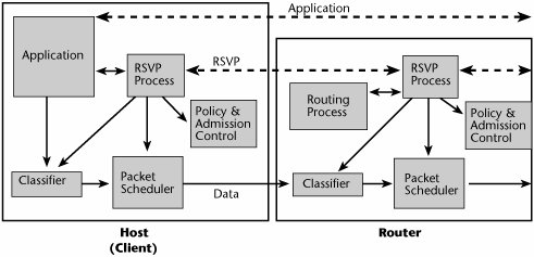
The IntServ model involves a classifier. Packets are mapped to a service class, and they are forwarded by a packet scheduler, based on their service class (see Table 10.4). Admission control determines whether the requested QoS can be delivered, and, as mentioned earlier, the setup protocol is RSVP. RSVP relies on router-to-router signaling schemes, which allow IP applications to request priority delay and bandwidth guarantees. Connections are established link by link, and a connection can be denied if a router cannot accept the request (see Figure 10.12). RSVP is particularly well suited for real-time applications and delay-sensitive traffic. RSVP allows applications to reserve router bandwidth. RSVP-guaranteed service provides bandwidth guarantees and a reliable upper bound to packet delays. But the resource requirements for running RSVP on a router increase proportionately with the number of separate RSVP reservations. This scalability problem makes using RSVP on the public Internet impractical, so it has largely been left to campus and enterprise-type networks.
Figure 10.12. RSVP in hosts and routers
|
Service Class |
Guaranteed Service |
Controlled Load Service |
Best-Effort Service |
|---|---|---|---|
|
End-to-end behavior |
Guaranteed maximum delay |
Best effort on unloaded network |
Best-effort only |
|
Intended applications |
Real-time |
Sensitive to congestion |
Legacy |
|
ATM mapping |
CBR or VBR-RT |
VBR-NRT or ABR with MCR |
UBR or ABR |
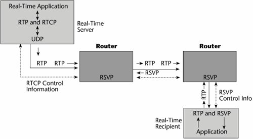
Several other protocols are associated with RSVP (see Figure 10.13). Real-Time Transport Protocol (RTP) is for audio, video, and so on. It is based on UDP, to cut down on overhead and latency. RTP is specified as the transport for H.323, and receivers can sequence information via the packet headers. Real-Time Transport Control Protocol (RTCP) provides status feedback from senders to receivers. Both RTP and RTCP are standardized by the ITU under H.225. Real-Time Streaming Protocol (RTSP) runs on top of IP Multicast, UDP, RTP, and RTCP.
Figure 10.13. RSVP and related protocols
RSVP is simplex (i.e., it is a reservation for unidirectional data flow), it is receiver driven (i.e., the receiver of data flows initiates and maintains the resource reservation for that flow), and it supports both IPv4 and IPv6. RSVP is not a routing protocol. Key issues regarding RSVP include scalability, security, and assurance that policy-based decisions can be followed. RSVP and related protocols are discussed in more detail in Chapters 8 and 9.
DiffServ
Today we concentrate more on DiffServ than on its parent, IntServ. The DiffServ approach to providing QoS in networks uses a small, well-defined set of building blocks from which a variety of services can be built (see Figure 10.14). A small bit pattern in each packet in the IPv4 Type of Service (ToS) octet, or the IPv6 Traffic Class octet, is used to mark a packet to receive a particular forwarding treatment or per-hop behavior at each network node. For this reason, DiffServ is really a CoS model: It differentiates traffic by prioritizing the streams, but it does not allow the specification and control of traffic parameters. DiffServ differentiates traffic by user, service requirement, and other criteria. It then marks the packets so that the network nodes can provide different levels of service via priority queuing or bandwidth allocation, or by choosing dedicated routes for specific traffic flows. DiffServ scheduling and queue management allow routers to act on the IP datagram. Service allocation is controlled by a policy management system. Routers can do four things after receiving an IP datagram: manage a queue, schedule interfaces, select which datagram is the logical choice for discard, and select an outbound interface.
Figure 10.14. DiffServ
DiffServ is a prioritization model with preferential allocation of resources based on traffic classification. As discussed in Chapter 8, DiffServ uses a DiffServ Code Point (DSCP) to select the servicethat is, the per-hop behaviorthat the packet will receive at each DiffServ-capable node. Queues then get different treatment in terms of priority, share of bandwidth, or probability of discard.
CBQ
Class-Based Queuing (CBQ) is a QoS tactic based on traffic management algorithms deployed at the WAN edge. CBQ is a fully open, nonproprietary technology that brings bandwidth-controlled CoS to IP network infrastructures. It allows traffic to be prioritized according to IP application type, IP address, protocol type, and other variables. It allocates unused bandwidth more effectively than other QoS mechanisms do, and it uses priority tables to give critical applications the most immediate access to unused bandwidth.
Policy-Based Management, COPS, and LDAP
A few additional concepts are relevant to QoS: policy-based management, COPS, and LDAP.
Policy-Based Management
The idea behind policy-based networking is to associate information about individual users, groups, organizational units, entire organizations, and even events (such as the beginning of the accounting department's month-end closing) with various network services, or classes of service. So on a very granular basis, and on a time-sensitive basis, you can ensure that each user is receiving the QoS needed for the particular application at a specific time and place.
COPS
COPS is an IETF query-response-based client/server protocol for supporting policy control over QoS signaling protocols, such as RSVP. It is part of the Internet Protocol suite, as defined by IETF RFC 2748. COPS addresses how servers and clients on a network exchange policy information, and it transmits information between a policy server and its clients, which are policy-aware devices such as switches.
COPS is composed of policy decision points (PDPs), which are servers on which policies are stored, and policy enforcement points (PEPs), the clients on which the policies are enforced. There are two COPS models:
- Provisioning Model In the Provisioning Model, the PEP reports its decision-making capabilities to the PDP, which then downloads the pertinent policies onto the PEP. The PEP uses these policies to make its own decisions. In this model, the policy information base is the repository of the policies.
- Outsourcing Model With the Outsourcing Model, the simplest mode, all policies are stored at the PDP. When a PEP needs to make a decision, it sends the relevant information to the PDP, which then analyzes the information and forwards a decision to the PEP. All the PEP has to do is enforce the decision.
An Internet Draft called COPS-MAID introduces QoS extensions for multi-access environments. The main benefits of COPS are that it creates efficient communication between policy servers and policy-aware devices, and it increases interoperability among different vendors' systems.
LDAP
LDAP, a standard directory server technology for the Internet, allows retrieval of information from multivendor directories. More specifically, it is a networking protocol for querying and modifying directory services running over TCP/IP. LDAP version 3 (LDAPv3) provides client systems, hubs, switches, and routers, as well as a standard interface to rewrite directory information. Equipment and directory vendors use LDAP for accessing and updating directory information. The current version, LDAPv3, is specified in IETF RFC 3377.
The MPLS Architecture
MPLS was created to address the weaknesses in traditional IP networks. Remember that IP was designed to support best-effort service. Routers do not see rings or connections; they see ports and addresses via the routing tables and proprietary priority cues. IP routing lacks intelligence. Least-cost routing causes traffic to take the shortest number of hops, which means traffic takes shorter, congested paths rather than longer, uncongested paths, leading to network hotspots and inconsistent performance.
A lot of attention is being focused now on the MPLS environment, which was born out of Cisco's tag switching. MPLS, which was designed with large-scale WANs in mind, was originally proposed by the IETF in 1997, and core specifications were completed in 2000. By plotting static paths through an IP network, MPLS gives service providers the traffic-engineering capability they need, and it also helps them build a natural foundation for VPNs. Remember that traffic engineering allows service providers to control QoS and optimize network resource utilization.
MPLS is one of the most significant developments in IP. MPLS is not an IP network, although it uses IP routing protocols such as OSPF and IS-IS and can run in routers. MPLS is not an ATM network, although it can use repurposed ATM cell switch hardware. MPLS is yet another type of network: It is a service-enabling technology. MPLS is a general-purpose tunneling mechanism that can carry IP and non-IP payloads. It uses label switching to forward packets or cells through the network, and it can operate over any data link layer.
MPLS separates the control plane from the forwarding plane. It thus enables the IP control plane to run on devices that cannot understand IP or recognize packet boundaries. The MP part of MPLS means it's multiprotocolit is an encapsulating protocol that can transport a multitude of other protocols. LS indicates that the protocols being transported are encapsulated with a label that is swapped at each hop. A label is a number that uniquely identifies a set of data flows on a particular link or within a particular logical link. The labels are of only local significance. They must change as packets follow a pathhence the switching aspect of MPLS.
Another benefit of MPLS is its potential to unite IP and optical switching under one route-provisioning umbrella. Because IP is a connectionless protocol, it cannot guarantee that network resources will be available. In addition, IP sends all traffic between the same two points over the same route. During busy periods, therefore, some routes become congested and others remain underutilized. Without having explicit control over route assignments, the provider has no way to steer excess traffic over less busy routes. One key difference between MPLS and IP is that in MPLS, packets sent between two points can take different paths based on different MPLS labels.
How MPLS Works
MPLS is connection oriented, like ATM and Frame Relay, and it makes use of label-switched paths (LSPs). MPLS tags, or adds a label to, IPv4 or IPv6 packets so they can be steered over the Internet along predefined routes. MPLS also adds a label that identifies the type of traffic, the path, and the destination. This allows routers to assign explicit paths to various classes of traffic. Using these explicit routes, service providers can reserve network resources for high-priority or delay-sensitive flows, distribute traffic to prevent network hotspots, and preprovision backup routes for quick recovery from outages.
As shown in Figure 10.15, an MPLS network is composed of a mesh of label-switching routers (LSRs). These LSRs are MPLS-enabled routers and/or MPLS-enabled ATM switches. They are core routers that ignore the IP packet header. LSRs forward packets based on labels, running IP routing protocols and some form of MPLS Label Distribution Protocol (LDP) to allocate and distribute the Forwarding Equivalence Class (FEC) and label bindings. Labels are contained in the packets or cells. They are used by the LSR to index the Label Information Base (LIB) during the label swap. The format is link-layer dependent. As each packet enters the network, an ingress LSR assigns it a label, based on its destination, VPN membership, ToS bits, and other considerations. At each hop, an LSR uses the label to index a forwarding table. The forwarding table assigns each packet a new label and directs the packet to an output port. To promote scaling, labels have only local significance. As a result, all packets with the same label follow the same LSP through the network.
Figure 10.15. How MPLS works
MPLS traffic engineering enables tunneling through an IP network. With FEC, a group of IP packets are forwarded in the same mannerthat is, over the same path and with the same forwarding instructions. LDP refers to the control protocols that operate between the LSRs. The LSP is established through a contiguous set of LSRs. The FEC allows treatment of traffic to be based on application, destination, or other parameters. It allows traffic to be grouped together and allows priorities to be established. The end result is that the responsibility is split between ingress, egress, and transit routers; heavy processing is done at the edges, and label forwarding is done at the core.
Service providers can specify explicit routes by configuring them into edge LSRs manually, or they can use one of two new signaling protocols: RSVP-TE, which is RSVP with traffic-engineering extensions, or MPLS LDP, which is augmented for constraint-based routing. Most equipment vendors support both.
With MPLS, network operators don't have to use explicit routingand they are not likely to in networks that have plenty of bandwidth. Instead, they can let ingress LSRs use LDP without any constraint-based extensions, to automatically associate labels with paths. With plain LDP, MPLS packets follow the same routes as ordinary routed packets. With MPLS, you can support all applications on an IP network without having to run large subsets of the network with completely different transport mechanisms, routing protocols, and addressing plans.
MPLS can switch a frame from any kind of Layer 2 link to any other kind of Layer 2 link, without depending on any particular control protocol. Compare this to ATM, for example: ATM can switch only to and from ATM and can use only ATM signaling protocols, such as PNNI or Interim Interface Signaling Protocol. MPLS supports several types of label formats. On ATM hardware, it uses the well-defined virtual channel identifier (VCI) and virtual path identifier (VPI) labels. On Frame Relay hardware, it uses a data link connection identifier (DLCI) label. Elsewhere, MPLS uses a new generic label, known as a shim, which sits between Layers 2 and 3. Because MPLS allows the creation of new label formats without requiring changes in routing protocols, extending technology to new optical transport and switching could be relatively straightforward.
MPLS Stacks
Label stacking is a powerful feature of MPLS that enables LSRs to insert an additional label at the front of each labeled packet, creating an encapsulated tunnel that can be shared by multiple LSPs. At the end of the tunnel, another LSR pops the label stack, revealing the inner label. An optimization in which the next-to-last LSR peels off the outer label is known in IETF documents as penultimate hop popping.
Whereas ATM has only one level of stacking (virtual channels inside virtual paths), MPLS supports unlimited stacking (see Figure 10.16). An enterprise could use label stacking to aggregate multiple flows of its own traffic before passing the traffic on to the access provider. The access provider could then aggregate traffic from multiple enterprises before handing it off to the backbone provider, and the backbone provider could aggregate the traffic yet again before passing it off to a wholesale carrier. Service providers could use label stacking to merge hundreds of thousands of LSPs into a relatively small number of backbone tunnels between points of presence. Fewer tunnels mean smaller routing tables, and smaller routing tables make it easier for providers to scale the network core.
Figure 10.16. MPLS stacks
Why MPLS?
MPLS adds two important elements to IP: virtual circuits and capacity reservation. Virtual circuits, in this context, are referred to as LSPs. LSPs provide security similar to that found in Frame Relay: Tunnels are used to isolate customer traffic. (But true security is not simply guaranteed through the use of tunnels; rather, true security means that customer traffic must be encrypted end to end.) MPLS also allows for capacity reservation, enabling the support of SLAs. Typical parameters might include a packet loss of less than 1% and a round-trip delay of less than 55 to 70 milliseconds.
Constraint-based routing is superior to IP because it bases routing decisions on more than just a shortest-path calculation. Hence, using MPLS may be the best way for service providers to provision VPNs that meet customer service quality metrics and permit ISPs to scale their networks and meet traffic-engineering requirements without having to resort to using ATM permanent virtual circuit (PVC) overlay networks.
In summary, MPLS adds QoS and virtual tunnels; it provides a common control plane between Layer 2 and Layer 3; it can support multiple Layer 2 protocols such as Frame Relay, ATM, and Ethernet; and it provides Layer 2 performance, which means it has the benefits of connection-oriented networks. MPLS is a compromise between connectionless Layer 3 and connection-oriented Layer 2, which means it provides deterministic behavior.
Using MPLS is the most effective way to integrate IP and ATM in the same backbone network. It reduces the processing overhead in IP routers, improving packet-forwarding performance. MPLS is also another way to provide QoS in network backbones, competing with or being complementary to DiffServ, IntServ's RSVP, and the ATM QoS architecture. Finally, it solves the n-squared route propagation problem in large backbones, where routers have to be interconnected with a mesh of ATM or Frame Relay virtual circuits.
Major efforts are under way to adapt the control plane of MPLS to direct the routing of not just LSRs but also an expanded universe of devices, including optical switches and other optical elements. This will allow optical switches, optical cross-connects, LSRs, regular IP routers, and even time division multiplexers to recognize each other and exchange information. The same routing system can control optical paths in the DWDM core, LSPs across the MPLS backbone, and paths involving any IP routers at the edge of the network. This is the realm of GMPLS, which is discussed in detail in Chapter 11. Whether with MPLS or GMPLS, service providers can simplify their operational procedures, deliver more versatile IP services, and, most importantly to customers, sign meaningful SLAs.
Part I: Communications Fundamentals
Telecommunications Technology Fundamentals
- Telecommunications Technology Fundamentals
- Transmission Lines
- Types of Network Connections
- The Electromagnetic Spectrum and Bandwidth
- Analog and Digital Transmission
- Multiplexing
- Political and Regulatory Forces in Telecommunications
Traditional Transmission Media
Establishing Communications Channels
- Establishing Communications Channels
- Establishing Connections: Networking Modes and Switching Modes
- The PSTN Versus the Internet
The PSTN
- The PSTN
- The PSTN Infrastructure
- The Transport Network Infrastructure
- Signaling Systems
- Intelligent Networks
- SS7 and Next-Generation Networks
Part II: Data Networking and the Internet
Data Communications Basics
- Data Communications Basics
- The Evolution of Data Communications
- Data Flow
- The OSI Reference Model and the TCP/IP Reference Model
Local Area Networking
Wide Area Networking
The Internet and IP Infrastructures
- The Internet and IP Infrastructures
- Internet Basics
- Internet Addressing and Address Resolution
- The Organization of the Internet
- IP QoS
- Whats Next on the Internet
Part III: The New Generation of Networks
IP Services
Next-Generation Networks
- Next-Generation Networks
- The Broadband Evolution
- Multimedia Networking Requirements
- The Broadband Infrastructure
- Next-Generation Networks and Convergence
- The Next-Generation Network Infrastructure
Optical Networking
- Optical Networking
- Optical Networking Today and Tomorrow
- End-to-End Optical Networking
- The Optical Edge
- The Optical Core: Overlay Versus Peer-to-Peer Networking Models
- The IP+Optical Control Plane
- The Migration to Optical Networking
Broadband Access Alternatives
- Broadband Access Alternatives
- Drivers of Broadband Access
- DSL Technology
- Cable TV Networks
- Fiber Solutions
- Wireless Broadband
- Broadband PLT
- HANs
Part IV: Wireless Communications
Wireless Communications Basics
- Wireless Communications Basics
- A Brief History of Wireless Telecommunications
- Wireless Communications Regulations Issues
- Wireless Impairments
- Antennas
- Wireless Bandwidth
- Wireless Signal Modulation
- Spectrum Utilization
Wireless WANs
- Wireless WANs
- 1G: Analog Transmission
- 2G: Digital Cellular Radio
- 5G: Enhanced Data Services
- 3G: Moving Toward Broadband Wireless
- Beyond 3G
- 4G: Wireless Broadband
- 5G: Intelligent Technologies
WMANs, WLANs, and WPANs
Emerging Wireless Applications
- Emerging Wireless Applications
- The Handset Revolution
- Mobile IP
- The IP Multimedia Subsystem
- Mobile Gaming
- Mobile Video
- Mobile TV
- Mobile Content
Glossary
EAN: 2147483647
Pages: 160
