The Transport Network Infrastructure
The transport network includes two main infrastructures. The first is the PDH, also known as T-carrier, E-carrier, and J-carrier wideband transmission standards. This infrastructure was first introduced in the early 1960s. The second infrastructure of the transport network is the Synchronous Digital Hierarchy (SDH; ITU terminology), also known as Synchronous Optical Network (SONET; ANSI terminology), which was first formalized and standardized in 1988. SDH/SONET is the second generation of digital hierarchy, and it is based on a physical infrastructure of optical fibers.
PDH and SDH/SONET are voice-centric circuit-switched network models that switch millions of 64Kbps circuits between various switching points. Each circuit is multiplexed numerous times for aggregation onto transmission facilities. Aggregation occurs at many points in the network: in the access network, within the local exchange, and throughout the interexchanges. Hence, a significant portion of the cost of a network goes to the equipment that performs this aggregationthe multiplexers and cross-connects in both the PDH and SDH/SONET environments.
The PDH Infrastructure
The term Plesiochronous makes PDH sound like a dinosaur, and in a way, it isit's an outdated architecture from the standpoint of the data rates it offers. But the word Plesiochronous means "minute variations in timing," which refers to the fact that PDH is an asynchronous infrastructure. Each network elementthat is, each exchange, multiplexer, cross-connect, repeater, and so ongets its clocking pulse from a different clocking source, and even though those clocking sources are synchronized, there are minute fluctuations in timing. To differentiate the beginning and the end of a conversation, PDH must channelize conversations.
PDH was the first system designed to use digitized voice transmission. It was born of the telcos' desire to better use their cable facilities and to enhance the quality of calls. PDH was first used by telcos as a means of aggregating multiple voice channels into a single high-speed digital backbone. Standards used today for all-digital switching and transmission come from the original PDH specifications.
PDH is an integrated digital network, so it can carry a range of traffic, as long as that traffic is presented in a digital manner. Therefore, PDH represented the first opportunity for users and carriers to combine voice and data traffic over the same pipes. In addition, it specifies the different transmission levels or data rates, some of which are available for customers to subscribe to and others of which are used by operators internally within the backbones. Finally, it defines within each of the transmission levels how many channels can be made available.
The T-, E-, and J-Carrier Standards
Various PDH standards are followed in different regions of the world: J-carrier (Japanese-carrier) in Japan, T-carrier (Terrestrial-carrier) in North America, and E-carrier (European-carrier) in Europe and most of Asia, Latin America, the Middle East, and Africa. Figure 4.4 compares these three standards. They all share one increment as a common denominator: A single channel carries 64Kbps. But each of the three standards multiplexes together a different number of these 64Kbps channels to derive higher transmission rates.
Figure 4.4. T-carrier, E-carrier, and J-carrier standards
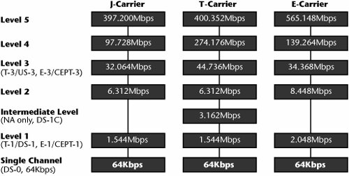
Having three separate standardsT-, E-, and J-carriernecessitates crossing between systems that use different standards, which causes additional overhead.
Elements of the PDH Infrastructure
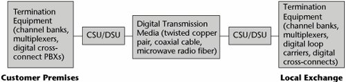
As shown in Figure 4.5 and described in the following sections, the following are the key elements of the PDH infrastructure:
- Transmission media
- Repeaters
- Channel service units (CSUs)/data service units (DSUs)
- Multiplexers
- Digital loop carriers (DLCs)
- Digital cross-connect systems (DCSs)
Figure 4.5. PDH components
Transmission Media
PDH can include a wide variety of transmission media, and the type you use is contingent on the bandwidth you want to support. You could use copper pairs to provision T-1, E-1, or J-1 services, but if you wanted to get into the higher-bandwidth capacities afforded under T-3, E-3, or J-3, you would deploy a higher-bandwidth medium, such as coax, microwave, or fiber. PDH operates on four-wire circuits, which means it operates in full-duplex and you can communicate in both directions simultaneously.
CSUs
A CSU terminates each end of a T-, E-, or J-carrier facility. It equalizes the received signal, filters the transmitted and received waveforms, and interacts with customers' and carriers' test facilities. You use a CSU to perform diagnostic tests on span lines and to set up a T-1, E-1, or J-1 line with a PBX, a channel bank, a multiplexer, or any other compliant data terminal equipment.
Multiplexers
A series of time division multiplexers enables us to move up the hierarchy of the PDH infrastructure. The first in the series of multiplexers is generally referred to as channel banks. A channel bank has several purposes. First, it consolidates the individual voice and data channels so that they can travel over the higher-speed transmission line. In the case of a T-1 line, a channel bank consolidates 24 channels; in the case of an E-1 line, a channel bank consolidates 32 channels. Channel banks can accept analog inputs, which means they can digitize analog voice. If you're using an analog switcheither a local exchange or a PBXthe channel bank should be equipped with the codecs that run an analog voice stream through a process of digitization called Pulse Code Modulation (PCM) to convert the analog voice into a digital bitstream that can be transported over the digital carrier. (Codecs are discussed in Chapter 1, "Telecommunications Technology Fundamentals," and PCM is discussed later in this chapter.)
Beyond the channel bank, the multiplexing hierarchy steps through the individual transmission levels. In the case of T-carrier, the levels are T-1 through T-4; for E-carrier, they are E-1 through E-5; and for J-carrier, they are J-1 through J-5.
DLCs
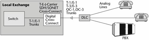
DLCsalso called remote terminals, concentrators, or remote concentratorswere introduced in the mid-1970s, specifically as a way to economically expand the telco network. They were deployed to improve efficiency and to lower costs. DLCs reduced analog facilities by up to 80%, and they led to building, real estate liquidation, and maintenance efficiencies as well. They also eliminated the need for loading coils, which are used to improve transmission on wire pairs for distances greater than 3.4 miles (5.5 km). DLCs also reduced the number of pairs of copper wires required between the local exchange and the subscriber; they did this by sharing pairs or transmission facilities among many multiplexed conversations. Essentially, the DLC architecture, shown in Figure 4.6, reduces the loop lengths and makes more effective use of high-capacity trunks from a neighborhood into the local exchange.
Figure 4.6. DLC architecture
DLCs continue to evolve, and as they do so, they become smaller systems. The original DLCs were built so that an individual system could service around 600 subscribers, but these boxes achieved only about a 50% fill ratio, which meant that half of the capacity was not being used. Now, given the distribution and density of neighborhoods and populations, smaller DLCs are being created. These systems service up to about 96 subscribers, and utilization is at around a 90% level. These smaller DLCs allow for faster service rollout and a shorter payback period for the deployment. They also facilitate quick response to growth in services and competition.
With ever-increasing interest in high-speed broadband access, DLCs could be a tool for shortening loop length, thereby bringing more bandwidth to the customer. Consequently, some of the additional changes that have occurred with the newer generations of DLCs also provide interfaces for SDH/SONET or optical fibers. However, the vast majority of DLCs deployed are incompatible with the xDSL services. It is imperative that the proper generation of DLC be deployed in order to meet the customer's demand for broadband residential access via twisted-pair.
DCSs
DCSs, developed in 1981 and officially introduced in 1985, basically automated the process of circuit provisioning and replaced the use of manual patch panels. The key feature of DCSs is called drop and insert, which refers to the capability of the cross-connect to exchange channels from one facility to another. It is used to implement appropriate routing of traffic, to reroute around congestion or failure, and to allow customers to dynamically reconfigure their own networks. Generally, drop and insert keeps communications paths in place for continuous use over a period of months, or sometimes even years, but it does allow change as demand warrants.
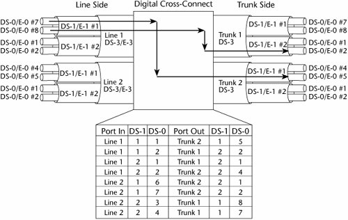
Essentially, a DCS is a computer system with a variety of software databases that describe first-choice routes and alternate routes (see Figure 4.7). If channel 7 normally goes out over line 1 and then goes out over trunk 1, but trunk 1 fails, the DCS can consult its alternate routing table, which might say to reroute that particular line over trunk 2. A reconfiguration can take place in a matter of minutes.
Figure 4.7. An example of a DCS
DCSs provide for different levels of switching. You can switch between DS-3s and DS-3s or between E-3s and E-3s. You can switch between DS-1s and DS-1s or between E-1s and E-1s. You can switch between DS-0s and E-0s, and you can also potentially switch below that level by using submultiplexed data streams within the DS-0 channel. Some of the individual intelligent multiplexers, such as T-1/E-1 muxes and T-3/E-3 muxes, also offer this capability.
The fact that reconfigurations can be implemented in a matter of minutesand that customers can implement this capability on their own private networksis the most important and favorable characteristic of DCSs. The main applications for cross-connects are to provide disaster recovery, to bypass a system during maintenance without affecting traffic flows, to reconfigure the network to address peak traffic demands, and to implement a temporary application that can be reconfigured as needed.
Voice Compression Standards
The following sections describe how voice was digitized to carry over the PSTN under the original sampling theorem.
PCM
PCM was developed in an environment that was largely analog. Therefore, in designing a digitization scheme, it was important to consider that voice would have to undergo many conversions between analog and digital as it was transmitted through the numerous switching nodes and components of a network. And if it had to go through a number of conversions, it could withstand only so many conversions before it began to lose toll quality. Therefore, the sampling theorem (i.e., the Nyquist theorem) that was developed stated that in order to reproduce voice in a toll-quality manner, you have to sample that voice at twice the rate of the highest frequency carried. The highest frequency being carried in the telephone channel was 4,000Hz, so we needed a sampling rate of 8,000 samples per second. Remember that a sample is a measurement of the amplitude, or voltage, of the signal at a particular point. Say that the amplitude of a signal is +1.25 volts. When we convert that amplitude value into a binary expression (an 8-bit word), we have 8,000 samples per second and 8 bits per sample, resulting in 64Kbps required to carry voice in a digital manner. This is how the 64Kbps channel was derived as the basic building block of PDH.
ADPCM
As networks become more digitized, fewer conversions take place, and voice can be carried at a higher quality over fewer bits per second. Another standard used in the PSTN is Adaptive Differential PCM (ADPCM), which carries digital voice at the compressed rates of 40Kbps, 32Kbps, 24Kbps, and 16Kbps. ADPCM does something wonderful for an end user. Say you have a traditional T-1 line with PCM channel banks. Over that one T-1, you can extract 24 channels, each of which carries 64Kbps. But your traffic increases, and you need more channels to carry voice traffic. You have two options: You can add another T-1 line, which means a substantial monthly investment, or you can put ADPCM channel banks on the T-1 that you already have, which gives you 48 channels of 32Kbps each. In essence, you can double the capacity of the network without having to add more subscriber lines.
Needless to say, voice compression continues to be applied, and not just in the PSTN. For instance, wireless networks such as cellular networks, where spectrum is at a premium, compress voice down to 8Kbps so that they can support more callers within each of the cells.
T-Carrier and E-Carrier Signal Hierarchy
Because competition has entered the marketplace, different operators in an area have often bought equipment from different manufacturers, which means there are a number of standards to deal with. Even if a country once followed ITU standards, new companies may have entered the country with North Americanstandard equipment and interfaced with the existing ITU-based equipment. Thus, it is important to be familiar with all the standards. The following sections cover the signal hierarchy for both T-carrier and E-carrier standards.
The T-Carrier Digital Signal Hierarchy
Table 4.1 lists the levels in the T-carrier digital signal hierarchy, the basic building block of which, DS-0, is the 64Kbps channel.
|
Digital Signal Level |
Bit Rate |
DS-0 Channel |
Number of T-1 Lines |
|---|---|---|---|
|
DS-0 (T-0) |
64Kbps |
1 |
|
|
DS-1 (T-1) |
1.544Mbps |
24 |
1 |
|
DS-2 (T-2) |
6.312Mbps |
96 |
4 |
|
DS-3 (T-3) |
44.736Mbps |
672 |
28 |
|
DS-4 (T-4) |
274.176Mbps |
4,032 |
168 |
The first subscriber level, Digital Signal level 1 (DS-1), provides 1.544Mbps and a total of 24 channels. The DS-2 level is not a subscriber level, nor is it used very frequently in the PSTN. You might see it installed on some campus networks, or perhaps to bundle some DS-1s out of a tandem exchange to a toll exchange.
DS-3 is a high-bandwidth alternative for subscribers, and it is used for interexchange trunks. Both users and carriers get 44.736Mbps with DS-3, which is a total of 672 channels that can carry combined voice, data, fax, and image traffic.
The DS-4 level is used only within the telco, again on interexchange trunks. DS-4 offers roughly 274Mbps and 4,032 channels.
Each of the DS or T, E, or J levels requires a separate multiplexing level. Because each of the muxes is driven by a different clocking source, they each bundle their channels in a slightly different framework. In building the 64Kbps channels up to a T-1 and then building those T-1s up to T-2s and those T-2s up to T-3s, everything is fine unless somewhere along the way one customer decides to extract some capacity to drop off that allocation midway. Say, for example, that you're in Washington, DC, and you need to connect to San Francisco. In Washington, DC, you'd have a T-1 coming into the local exchange, along with multiple other customers in the neighborhood. The local exchange might bundle those T-1s onto a T-2 to pass off to the tandem, and the tandem would bundle them up into T-3s to send to the toll center. The toll center would bundle them up for T-4s to pass across the long haul to San Francisco. This works great until you need to add an office in Kansas City. You need to then add a T-4 mux to break it down to all the respective T-3s. Then you need to break down the T-3s into their T-2s, and then break down the T-2s into all their T-1s, and then find your T-1 so that you can extract the channels you want to drop off. Then you need to bundle them all back up onto the T-1 and go back up the scale again. This strict hierarchy (thus the use of the term hierarchy in the names of these technologies) requires you to go through all the changesyou can't jump steps as you bundle and unbundle traffic. Therefore, the PDH hierarchy is characterized by a lot of back-to-back multiplexing and demultiplexing in order to drop and add payload. That is one of the highest-cost components of this generation of the PSTN.
The E-Carrier Digital Signal Hierarchy
As shown in Table 4.2, E-carrier signals are often called CEPT levels (for the European Conference of Postal and Telecommunications Administrations); 64Kbps is the basic increment in E-carrier. CEPT-1 (or E-1) operates at 2.048Mbps and is delivered over 32 channels. Of these 32 channels, 30 carry information, and the remaining 2 carry control information (1 for framing, and 1 for signaling information).
|
CEPT Signal Level |
Bit Rate |
E-0 Channel |
Number of E-1 Lines |
|---|---|---|---|
|
CEPT-0 (E-0) |
64Kbps |
||
|
CEPT-1 (E-1) |
2.048Mbps |
32 |
1 |
|
CEPT-2 (E-2) |
8.488Mbps |
128 |
4 |
|
CEPT-3 (E-3) |
34.368Mbps |
512 |
16 |
|
CEPT-4 (E-4) |
139.246Mbps |
2,048 |
64 |
|
CEPT-5 (E-5) |
565.148Mbps |
8,192 |
256 |
CEPT-2, like T-2, is not used much. CEPT-3, the high-bandwidth alternative, offers 34Mbps and 512 channels. CEPT-4 and CEPT-5 are largely used within telco networks, again for their interexchange trunks. Like T-carrier, E-carrier has a strict hierarchy of multiplexers.
The SDH/SONET Infrastructure
SDH/SONET, created in the mid-1980s, is the second generation of digital hierarchy. Whereas PDH involves a lot of overhead because it includes three standards throughout the world, SDH/SONET uses one common standard that applies to networks worldwide. SDH, originally defined by the European Telecommunication Standards Institute (ETSI) for Europe, is now the most common form, used everywhere except for Japan and North America. Japan uses a version of SDH that varies slightly in some details. SONET is the American National Standards Institute (ANSI) standard, which is part of SDH, and it is used in North America. SDH/SONET was created to be an industry standard for high-speed transmission over optical fiber. It was actually part of a much bigger standard in the works at that timeBroadband ISDN. Broadband ISDN was envisioned for use with advanced applications (e.g., tele-education, telesurveillance, telemedicine, the ability to collaborate, HDTV). Two technologies were required in order to support such applications: a transport infrastructure (SDH/SONET) that had the significant bandwidth needed to support the applications and a switching technology (ATM) that could ensure that latencies could be controlled and kept very low. Consequently, SDH/SONET and ATM, as modern broadband technologies, were both born out of the Broadband ISDN standard and a desire to deliver advanced applications.
SDH/SONET is a family of transmission standards designed to achieve compatibility between different fiber-optic transport products as well as to provide compatibility with the existing digital hierarchy, PDH. A lot of fiber-optic systems have been deployed since 1984, but they're not all compatible with one another. They use different forms of cables with different diameters, and they use different types of light sources. And where there are physical incompatibilities, you can't achieve midspan meetwhere two carrier services have to come together. A railroad analogy can be used here. Think back to when people had just begun to build railroads. Often, one provider was building tracks going east to west that were a certain width, and another provider was building tracks going west to east that were a different width. When the providers met in the middle, their cars couldn't cross each other's tracks. The same thing happens when there's a lack of physical compatibility in fiber-optic transport, and that means you lose the ability to carry network management information on an end-to-end basis. You may not be able to do end-to-end monitoring and control of a network that is multivendor or multicarrier in nature if the vendors or carriers use incompatible physical fiber-optic equipment.
It's always important to develop and have available very strong network management tools. The goal of network management is not to eliminate downtime because we know that would be impractical; rather, it is to minimize the resolution time. So the ability to do end-to-end testing remotely is very critical to quick recoverability. SDH/SONET provides the physical layer (i.e., Layer 1) framework for broadband applications. It provides a standardized list of optical parameters that define the allowed types of cables and light sources. It defines a new table of data rates that are much higher than older transmission rates. It redefines how the multiplexing process occurs as you move within the different transmission levels. It also affords very robust operations capabilities, such as service restoration.
The SDH/SONET specifications define a frame formatthat is, how the bits are packaged together to be transported over the fiber. As mentioned earlier, they define the nature of the physical interfaces (e.g., couplers, light sources). They define the optical carrier line rates, or transmission levels, and they define the sorts of messages that are exchanged in order to support operations, administration, maintenance, and provisioning.
An important aspect of SDH/SONET is that it introduced the notion of a ring topology to address network survivability by providing rapid restoration. SDH/SONET uses a dual-counter-rotating ring. Imagine that you have four network nodes. As shown in Figure 4.8, with a dual-counter-rotating ring, you link each of these four network nodes together by using one pair of fibers; that pair of fibers becomes the primary fiber, and information flows over it in a clockwise manner. You run another pair of fibers, which may actually be housed in the same cable as the first pair of fibers, to join the four nodes. The second pair of fibers becomes the protect fiber, which is designed to carry information in a counterclockwise manner. In theory, if a cable is cut between node A and node B, you can still move a message from A to B by reversing the information flow and going from A to D to C to B. This enables you to recover almost immediatelywithin 50 millisecondsfrom outages that occur.
Figure 4.8. SDH/SONET ring architecture
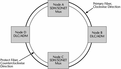
The survivability of an SDH/SONET ring depends on how the cables are engineered; if both cables share a common housing, then it's likely that a cable cut by a construction crew will stop operating in both directions. Similarly, if a major earthquake hits and all the streets are broken up, a counter-rotating ring will not necessarily ensure survivability, but for smaller-scale problems, it can very adequately handle a backup. This is one of the greatest strengths of SDH/SONET and will likely keep it operational in networks for another 10 to 20 years. But these types of capabilities are also being introduced in the new generations of standards, such as WDM, and when that occurs, we will start to move away from SDH/SONET because SDH/SONET is a Time Division Multiplexing (TDM) system that does not take advantage of the fact that light can be spatially multiplexed, allowing multiple wavelengths to be carried over one fiber pair. Still, at this point, the flexibility of adding and dropping payload is one of the main reasons telcos still prefer SDH/SONET over other options: They can more easily integrate SDH/SONET into their billing systems. Although more and more customers are requesting Gigabit Ethernet, few telcos provide it.
SDH/SONET is also important because it grooms and routes traffic. Grooming means that SDH/SONET selectively removes channels from a digital facility for routing to a designated remote location via another digital facility; basically, it enables you to drop and add payload flexibly. SDH/SONET also provides for performance monitoring so that you can understand the performance of the network, its components, and the congestion levels.
The SDH/SONET Signal Hierarchy
The SDH/SONET signal hierarchy deals with optical carrier (OC) levels, which refer to the optical aspect of the transmissionthe optical pulse as it travels through the fibers. These optical pulses go through electronic muxes, and when the signal is going through these network elements, the bits are packaged in a frame for transport across the fiber. In the case of SONET, this frame is called the Synchronous Transport Signal (STS), and in SDH, the frame is called the Synchronous Transport Module (STM). Two types of rates are important in the realm of SDH/SONET: The payload rate refers to the capacity available to carry customer content, and the data rate refers to the total capacity available for customer content as well as network management information.
Table 4.3 shows the SDH/SONET signal hierarchy. You don't have to memorize all these levels, but you'll consistently encounter four or five of them in your readings that you should commit to memory. The following are the levels of the SDH/SONET signal hierarchy that you need to be familiar with:
- OC-1 OC-1 offers about 51Mbps and is generally used as customer access lines. Early-adopter types of customerssuch as universities, airports, financial institutions, large government agencies, and ISPsuse OC-1.
- OC-3 OC-3 provides about 155Mbps. End users such as companies in the aerospace industry and high-tier ISPs need this extensive level.
- OC-12 OC-12 provides about 622Mbps. It is another capacity toward which high-tier ISPs are moving. It was originally deployed for the metropolitan area fiber rings built out across cities worldwide, although those rings are now moving to OC-48.
- OC-48 OC-48 offers about 2.5Gbps. This capacity has been deployed for backbone, or core, networks. Today the metropolitan area rings are moving from OC-12 to OC-48, and the backbone links are moving from OC-48 to OC-192.
- OC-192 OC-192 supports about 10Gbps and is being used for backbone networks.
|
OC Level |
SONET |
SDH |
Data Rate (Mbps) |
Payload Rate (Mbps) |
|---|---|---|---|---|
|
OC-1 |
STS-1 |
STM-0 |
51.48 |
50.840 |
|
OC-3 |
STS-3 |
STM-1 |
155.52 |
150.336 |
|
OC-9 |
STS-9 |
STM-3 |
466.56 |
451.008 |
|
OC-12 |
STS-12 |
STM-4 |
622.08 |
601.344 |
|
OC-18 |
STS-18 |
STM-6 |
933.12 |
902.016 |
|
OC-24 |
STS-24 |
STM-8 |
1,244.16 |
1,202.688 |
|
OC-36 |
STS-36 |
STM-12 |
1,866.00 |
1,804.032 |
|
OC-48 |
STS-48 |
STM-16 |
2,488.32 |
2,405.376 |
|
OC-96 |
STS-96 |
STM-32 |
4,876.64 |
4,810.752 |
|
OC-192 |
STS-192 |
STM-64 |
9,953.28 |
9,621.504 |
|
OC-768 |
STS-768 |
STM-256 |
39,813.12 |
1,327.104 |
Although there are more levels in the SDH/SONET signal hierarchy, the ones discussed here are the ones for which equipment is currently manufactured. We are in the early stages of deploying new muxes that operate at OC-768 and support 40Gbps. As of mid-2006, use of OC-768 connections outside research or testing networks was very rare, largely due to the fact that they are very expensive. However, given that it is the next logical speed step in the SDH/SONET hierarchy, it is predicted that there will be greater adoption of this standard going forward. On the other hand, some people feel that electronic muxes really are not suitable for the higher data rates being made possible by advances in optical technologies and that we should concentrate on moving to all-optical muxes and switches instead.
How do the high optical carrier levels relate to all the lower-level signals out theresuch as those from a 1.5Mbps T-1 or a 2Mbps E-1? There are mechanisms that enable us to map signal levels below DS-3 (i.e., below 45Mbps) into what SDH calls virtual containers or what SONET calls virtual tributaries. A virtual container or tributary basically defines the data structure for the transport and switching of sub-51Mbps network services such as DS-1, E-1, DS-2, and E-3. Table 4.4 shows the various line rates that are supported and what existing standard each refers to. For most people, this type of detail won't make or break success in the industry, but it's important to know that a virtual tributary or virtual container can provide a highway for lower-rate data signals to coexist in high-speed optical pipes.
|
Virtual Container/Virtual Tributary Level |
Line Rate |
Standard |
|---|---|---|
|
VC-11/VT-1.5 |
1.728Mbps |
DS-1/E-1 |
|
VC-2/VT-2 |
2.304Mbps |
E-1 |
|
VT-3 |
3.456Mbps |
DS-1C |
|
VC-2/VT-6 |
6.912Mbps |
DS-2 |
|
VT-6-N |
n x 6.9Mbps |
(Future) |
|
Async DS-3/VC-3 |
44.736/34.368Mbps |
DS-3/E-3 |
|
VC-4 |
139.264Mbps |
DS-4/E-4 |
In contrast to PDH, SDH/SONET is a synchronous infrastructure. This means that each of the network elements draws its clocking pulse from one clocking sourceso everybody is marching to the beat of the same drummer. Instead of using special framing bits to delineate channels, SDH/SONET uses a special pointer bit in front of each conversation that essentially says "start of a new conversation." When it's time to drop that channel off at a customer's premises, it is possible to identify it by its pointer bit and extract it without having to disturb any of the other traffic. This reduces the overhead associated with multiplexers by a factor of 10.
SDH/SONET Muxes and Cross-Connects
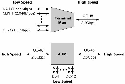
SDH/SONET was built for and largely relies on fiber-optic transmission media. It also includes a variety of multiplexers and cross-connects, as well as equipment that could be placed at the customer's premises. There are two main categories of SDH/SONET multiplexers (see Figure 4.9):
- Terminal muxes Terminal muxes enable signals to move through the hierarchy of optical carrier levels. They act as access nodes and support current services by accepting electrical interfaces and lower-level signals, including DS-1/E-1, DS-2, and DS-3/E-3. They concentrate one or more optical carrier signals and represent one of the optical carrier levels.
- Add/drop muxes (ADMs) ADMs facilitate easy dropping and adding of payload and are therefore the building blocks of the SDH/SONET network. An ADM converts one or more lower-level signals, such as T-1 or E-1 signals, into and from one of the optical carrier levels. It can drop lower-rate signals to be transported on different facilities, or it can add lower-rate signals into the higher-rate optical carrier levels, and basically it allows telcos to add and drop traffic easily and conveniently all along the network.
Figure 4.9. Terminal muxes versus ADMs
There are also two categories of SDH/SONET cross-connects:
- Wideband DCSs These terminate SDH/SONET and DS-3/E-3 signals. Switching occurs at the DS-0, DS-1/E-1, and VT/VC levels.
- Broadband DCSs Broadband DCSs interface at the various SDH/SONET signal levels as well as the legacy DS-3/E-3 levels, but they then switch at the optical carrier levels. They can make cross-connections at DS-3/E-3, OC-1, and concatenated levels (i.e., where several frames of an OC-1 are combined). Generally, a broadband DCS is used as an SDH/SONET hub that grooms the optical carrier levels for broadband restoration purposes or for routing traffic.
Part I: Communications Fundamentals
Telecommunications Technology Fundamentals
- Telecommunications Technology Fundamentals
- Transmission Lines
- Types of Network Connections
- The Electromagnetic Spectrum and Bandwidth
- Analog and Digital Transmission
- Multiplexing
- Political and Regulatory Forces in Telecommunications
Traditional Transmission Media
Establishing Communications Channels
- Establishing Communications Channels
- Establishing Connections: Networking Modes and Switching Modes
- The PSTN Versus the Internet
The PSTN
- The PSTN
- The PSTN Infrastructure
- The Transport Network Infrastructure
- Signaling Systems
- Intelligent Networks
- SS7 and Next-Generation Networks
Part II: Data Networking and the Internet
Data Communications Basics
- Data Communications Basics
- The Evolution of Data Communications
- Data Flow
- The OSI Reference Model and the TCP/IP Reference Model
Local Area Networking
Wide Area Networking
The Internet and IP Infrastructures
- The Internet and IP Infrastructures
- Internet Basics
- Internet Addressing and Address Resolution
- The Organization of the Internet
- IP QoS
- Whats Next on the Internet
Part III: The New Generation of Networks
IP Services
Next-Generation Networks
- Next-Generation Networks
- The Broadband Evolution
- Multimedia Networking Requirements
- The Broadband Infrastructure
- Next-Generation Networks and Convergence
- The Next-Generation Network Infrastructure
Optical Networking
- Optical Networking
- Optical Networking Today and Tomorrow
- End-to-End Optical Networking
- The Optical Edge
- The Optical Core: Overlay Versus Peer-to-Peer Networking Models
- The IP+Optical Control Plane
- The Migration to Optical Networking
Broadband Access Alternatives
- Broadband Access Alternatives
- Drivers of Broadband Access
- DSL Technology
- Cable TV Networks
- Fiber Solutions
- Wireless Broadband
- Broadband PLT
- HANs
Part IV: Wireless Communications
Wireless Communications Basics
- Wireless Communications Basics
- A Brief History of Wireless Telecommunications
- Wireless Communications Regulations Issues
- Wireless Impairments
- Antennas
- Wireless Bandwidth
- Wireless Signal Modulation
- Spectrum Utilization
Wireless WANs
- Wireless WANs
- 1G: Analog Transmission
- 2G: Digital Cellular Radio
- 5G: Enhanced Data Services
- 3G: Moving Toward Broadband Wireless
- Beyond 3G
- 4G: Wireless Broadband
- 5G: Intelligent Technologies
WMANs, WLANs, and WPANs
Emerging Wireless Applications
- Emerging Wireless Applications
- The Handset Revolution
- Mobile IP
- The IP Multimedia Subsystem
- Mobile Gaming
- Mobile Video
- Mobile TV
- Mobile Content
Glossary
EAN: 2147483647
Pages: 160
