End-to-End Optical Networking
At this point in the optical networking revolution, we're striving for what will be an end-to-end optical architecture, which means that nowhere in the network is the optical signal converted into an electronic signal. This reduction in the processing of signals would reduce costs and ultimately provide better performance.
No other transmission medium can unlock the same level of available bandwidth as can the visible light spectrum. But today, electronic network equipment acts as the bottleneck. Fibers now can carry terabits per second (Tbps), but they terminate on equipment that, at best, can handle gigabits per second (Gbps). Before we can unleash the possibilities and realize the savings of end-to-end optical networking, we need to replace all the existing electronic equipment with optical equipment, which, of course, will be costly. It will involve not only new hardware but also new skill sets and network management solutions.
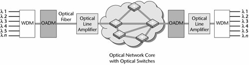
An end-to-end optical network includes the following components:
- Optical line amplifiers, such as erbium-doped fiber amplifiers (EDFAs), Raman amplifiers, and semiconductor optical amplifiers (SOAs)
- WDM equipment
- OADMs, including ROADMs
- Optical switches
- Integrated photonic circuits
Figure 11.4 shows an example of an optical network that incorporates these components. The following sections describe them, as well as the role of network management systems, in more detail.
Figure 11.4. Optical network components
Optical Line Amplifiers: EDFAs, Raman Amplifiers, and SOAs
As mentioned in Chapter 1, EDFAs, which were introduced in 1994, were a key innovation in the fiber world because they meant that an optical signal could be amplified without having to undergo any conversions. Before EDFAs, electronic regenerators had to extract signals, retime them, and then regenerate them. This conversion limited data rates to 2.5Gbps. EDFAs quadruple this speed, providing data rates of 10Gbps. EDFAs have also opened the door to the development of wavelength division multiplexers, which enable incredible expansion of capacity on fiber optics. (Wavelength division multiplexers are discussed in detail later in this chapter.)
Composed of erbium metal and doped with special atoms, EDFAs are incorporated in optical fiber at periodic intervals, generally 30 to 60 miles (50 to 100 km), to boost communication signals. The components in an EDFA include an erbium-doped fiber, a laser-pump diode, couplers, and isolators. The light to be amplified is coupled in a section of erbium-doped fiber together with light from a laser-pump diode, normally about 980 nm. The EDFA itself operates in the range of 1,550 nm. The light from the laser-pump diode boosts the 1,550-nm light and is separated on the exit route. An isolator at each end protects the system from unwanted reflections.
Just as EDFAs were critical to the development of WDM, future advances in WDM capacity also require new developments in amplifiers. One approach to increasing the capacity of WDM systems is to expand the usual frequencies to make room for more channels. However, EDFAs present a problem: They boost light only in the C-band (1,530 to 1,565 nm) and L-band (1,565 to 1,625 nm), and a different EDFA is required in each band. To use both bands, a 5-nm separation is required between bands, and the unused bandwidth represents about 120Gbps of lost capacity. One solution to the problem posed by EDFAs is to use Raman amplifiers. A Raman amplifier uses a powerful laser source to boost the signal power in standard optical fiber. A single Raman amplifier can boost both C- and L-bands, eliminating the need for the 5-nm separation, thereby increasing capacity.
Another development in amplifier technology is the emergence of the SOA, which is built on a single chip. SOAs can be integrated into multifunction optical chips and can be less expensive than EDFAs. The disadvantage of SOAs is a higher signal-to-noise ratio. However, SOAs are attractive for optical signal processing (e.g., all-optical switching, wavelength conversion). Much research is therefore being done on SOAs as optical computing components.
WDM Equipment
WDM works by spatially separating, or multiplexing, different wavelengths of light down a single optical fiber. Current fiber-optic systems use only a fraction of the available bandwidth. They carry just one wavelength, when, in fact, thousands of wavelengths can be derived. The data rate supported by each wavelength depends on the type of light source. Today, each wavelength can carry from 2.5Gbps (OC-48) to roughly 10Gbps (OC-192). Recently we have seen some deployment of 40Gbps (OC-768) systems, but we are in the early stages of deploying that level. Nonetheless, in the very near future, we're expecting the delivery of Tbps light sources, and by 2010, we expect to see lasers operating in the petabits per second (Pbps) range. (With speeds in the Pbps range, the time between bursts is the same time that light takes to travel one-eighth the width of a human hair.)
WDM furnishes separate channels for each service at the full rate. The idea is not to aggregate smaller channels into one larger channel but to provide a very high-speed channel that can terminate on today's switches and routers that, in fact, support 2.5Gbps and 10Gbps interfaces.
WDM systems are generally divided into two market segments: dense (DWDM) and coarse (CWDM). While the definitions often overlap, generally a DWDM system supports more than 8 wavelengths and is used in long-haul transport networks. Both the WDM and DWDM terminology are used to describe this network element. DWDM systems today support in the range of 1 to 192 wavelengths, but every year, new systems are introduced that support increasing numbers of wavelengths.
CWDM was specifically developed for metro area applications. It supports fewer wavelengths than DWDM, but it uses less expensive lasers, making it cost-effective for metro deployments, cable TV, and enterprise networks. While both DWDM and CWDM are based on the same principle of accommodating multiple wavelengths on a single fiber, they differ in terms of the type of light source used, the spacing between wavelengths, the total number of channels supported, the distance over which they operate, and the type of amplifiers used. And it is important to note that at this time, DWDM and CWDM systems are not interoperable; they are incompatible when operating on the same network, but because CWDM is less expensive, it is often used. This remains an issue that needs to be resolved.
The potential exists for transmitting thousands of channelspotentially as many as 15,000 wavelengths on a single fiberwith developments such as Bell Labs' chirped-pulse WDM. The idea of chirped pulse involves a specialized mode-locked laser, which rapidly emits very wide pulses of light. Because each part of a fiber interacts differently with varying frequencies of light, the result of chirped-pulse WDM is unequal dispersion. The pulse is stretched out when it enters the fiber, and data can be put on the discrete frequencies that emerge. You can think of this process in terms of a horse race: When a race starts, horses emerge together from the gate, but because each horse keeps a separate pace, spaces soon develop between the horses. This is the same type of stretching out that happens to the laser light in chirped-pulse WDM.
If we couple the potential for 15,000 wavelengths on one fiber with each of those wavelengths supporting Pbps, we have an explosion of bandwidth that is like nothing we have known before. As fantastic as all this sounds, we're likely to see even greater achievements; after all, we are still in the very early stages of knowledge about what we can achieve with optical networking. Before any real progress can be made, the realm of microphotonics, or integrated photonic circuits, must mature.
DWDM Developments and Considerations
As the number of wavelengths increases and the difference between the wavelengths gets smaller, the need for wavelength stability becomes greater to ensure that the optical carriers do not bump into each other. Getting this stability requires either a stock of boards for each wavelength (maintained by network operators) or tunable lasers. If you have 320 wavelengths, you need 320 separate boards, each tuned to the appropriate wavelength. For redundancy purposes, you need a backup for each of those boards. And you need this at each location where you have a wavelength division multiplexer. You can see that a tunable laser that could adopt the behavior of a specific frequency as needed would greatly reduce the operating cost and the costs of spare parts and inventory.
DWDM is beginning to be able to address network survivability requirements. It is also now capable of incorporating highly valued SDH/SONET-like capabilities, including monitoring performance, providing protection, and provisioning optical channels. As mentioned in Chapter 4, SDH/SONET introduced the network survivability tactic. The dual-counter-rotating rings provide a protected fiber path over which information can be shunted in the opposite direction if a fiber ring is broken. Until recently, DWDM had no such capability. It was deployed as a point-to-point link; if the fiber was cut, communication between the two DWDM systems was lost. But now we are beginning to see the introduction of restoration capabilities in DWDM platforms, which means that SDH/SONET will have a more limited life in the future. Industry forecasts predict that SDH/SONET has perhaps a 10-year lifespan left, after which the benefits of DWDM will override the reliability factors that we today associate with SDH/SONET. Remember that SDH/SONET is a TDM system, and therefore it cannot take advantage of the capacity gains that DWDM systems provide.
A different consideration emerges as DWDM systems continue to develop. Because of a combination of nonlinearities and dispersion, the majority of the fiber currently in place around the worldpossibly 95% of itwould have trouble carrying very fast (Tbps speed and Pbps pulses) signals for long distances in a DWDM system. These impairments that exist in current fiber can lead to crosstalk among the different wavelengths, interference between consecutive pulses on any signal wavelength, and degradation in the overall signal-to-noise ratio. This means that much of the fiber we have deployed over the past two decades will have to be replaced in order to take advantage of the new generation of optical equipment. Fiber solutions exist today, but time and financial resources will be needed to deploy them.
Where DWDM Fits in the Network Architecture
The core network was the first place DWDM was deployed because that is where the economics made the most sense. Increases in intercity traffic required carriers to expand the capacity of their long-haul pipes. The response was to deploy those point-to-point links with DWDM. This resolved the bandwidth problem, but it did nothing to address the routing issues. WDM and DWDM currently lack the intelligence required to really deliver meshed network configurations, and thus we have a need for optical switches. The main benefit of DWDM in the core is that it reduces deployment costs by eliminating the need for expensive amplifiers. Current DWDM products can operate successfully over about 300 to 450 miles (480 to 725 km), and there are examples of successful transmission up to 4,000 miles (6,400 km) without signal boosting. As mentioned earlier in this chapter, the process of regenerating signals represents as much as half of the overall cost of an optical deployment. Therefore, developments in extending distances are very promising.
In the quest for expanding the capacity of WDM systems, in addition to employing new generations of amplifiers, such as Raman amplifiers, another strategy is to pack channels together more closely. This applies primarily to long-haul systems. Current DWDM systems space channels at 50GHz, but tighter spacing is also possible, including 25GHz and 12.5GHz spacing. Tighter spacing requires precise lasers and channel separators.
CWDM
A vital application for WDM is in metropolitan area networks (MANs). MANs are becoming saturated, and network expansion is costly: Pulling fiber along existing conduits costs about US$30,000 per mile. But traditional DWDM systems are not well suited to MANs. For one thing, they were designed to work well on point-to-point links, but MAN traffic must be dropped and added frequently. DWDM does not present the same cost justifications in the MAN as it does in the core.
The great savings that can come with DWDM in the MAN are due to the reduction in the need for expensive amplifiers because, by definition, a MAN spans a fairly short distance. You can spend US$20,000 to US$30,000 or more for an amplifier that is capable of operating over a range of 300 to 450 miles (480 to 725 km). However, runs in MANs are typically no longer than 70 miles (110 km), so these expensive amplifiers are often overkill. As a result, the next generation of MAN products, designed to address the MAN corethat is, metro access, cable TV, and enterprise networkshas been introduced. These CWDM products are used for building citywide rings, covering distances of up to 37 miles (60 km). They generally support longer distances and greater capacity than do metro access products. Metro access products, such as passive optical networks (PONs), are designed to bring fiber closer to the customer. Enterprise products address building high-capacity campus networks. In all three of these MAN sectors, the issues are the same: pricing, scalability, access, and flexibility.
As far as pricing and scalability issues go, the lower carrying capacity and distance requirements in the metro area allow providers to reduce costs by using less expensive lasers. The price of a transponder board, which represents 90% of the cost of a laser, can vary by 25%, depending on the quality of the laser. Shorter-distance lasers use less-expensive modulation and amplification techniques. Whereas long-haul lasers are externally modulated, enabling the signal to travel up to 450 miles (725 km), shorter distances may allow direct modulation, where the laser runs only 50 to 60 miles (80 to 100 km) but costs 30% to 40% less than a long-haul laser. But less expensive lasers also mean less capacity. The lower grade of light sources requires greater spacing between the wavelengths, thereby reducing the number of channels or wavelengths that can be derived by up to 50%.
To meet these new demands, we need a very dynamic network that has the capability to accommodate huge capacity requirements and to change the configuration of that capacity dynamically. Subscribers want to connect at the current speed of their backbone. They want to make a direct connection through MANs and long-haul networks, with the associated protocols. And, of course, they want guaranteed QoS.
IP over WDM
Today, bandwidth reservation and intelligent IP switches can prioritize voice and video traffic to ensure that high-priority traffic gets the first shot at the underlying bandwidth. New generations of IP-based switches provide the capability to meet QoS commitments. Layer 3/Layer 4 switching services allow the switch to prioritize and guarantee packets, based on predetermined criteria within a switch. Higher-level protocols (such as RSVP) can reserve bandwidth across an entire network. This creates a value proposition for the service provider: The ISP can deliver high bandwidth in a format that users want, for less cost, while approximating the QoS guarantees that the end user expects for high-priority traffic.
As discussed in Chapter 4, the PSTN was not built to be dynamic. It was based on a system of 64Kbps channels, or DS-0s/CEPT-0s, aggregated by time division multiplexers into DS-1/CEPT-1 or DS-3/CEPT-3 facilities that would deliver traffic into cross-connects and switches at the network core. More time division multiplexers were required at the other end to reverse the process and to distribute the DS-0s/CEPT-0s. Time division multiplexers are expensive, and they often require manual configuration, which slows provisioning and further increases costs.
Whereas TDM is reaching its limits in terms of network elements and switching technologies, DWDM is just beginning. But with any new technology, obstacles arise, and in the case of DWDM, the obstacles include management and performance impedance mismatches between networks. The International Telecommunication Union (ITU; www.itu.int) has formed a study group that will look into the interoperability standards to ensure that traffic can move between vendor networks despite the underlying differences in the many different vendors' equipment.
Emerging WDM Applications
Emerging WDM applicationsfor example, extensive data (Ethernet) services, such as broadband access and video delivery (e.g., VOD) in cable networksaddress the growing desire for wavelength-on-demand, where individual wavelengths are assigned either to specific protocols, such as ATM, IP, or MPLS, or to specific customers. Alternatively, some providers might lease an entire dark fiber to each client, and the client would then purchase the CPE to route different protocols over each individual wavelength. This is opening the door to a whole new way of thinking about providing wavelengths to the long-haul carriers, to the MAN market, and to the customer.
The development of managed wavelength services depends on the development of wavelength changers and optical switches. A wavelength changer converts an optical signal to an electronic signal and then sends it to a laser that produces an optical signal at a different wavelength than the original. Optical switches give carriers the ability to provision bandwidth automatically, enable them to build mesh optical restoration, and allow them to establish QoS levels associated with restoration. (Optical switches are discussed later in this chapter.)
OADMs
Next-generation network services must be easily reconfigurable, and they must support real-time provisioning. Demultiplexing all the wavelengths at each node is costly, it introduces delay, and it reduces the distance over which a signal can travel. OADMs, as shown in Figure 11.5, work much more inexpensively than demultiplexing all the wavelengths because they simplify the processthey eliminate the costly electronics used to convert between light and electricity. Most OADMs use special filters to extract the wavelengths that need to be dropped off at a given location. For most vendors, the wavelength is fixed, so at the time of configuration, the carrier designates the individual wavelengths to be dropped at each location.
Figure 11.5. Optical add/drop multiplexing
The ROADM is a fairly new variety of add/drop mux (ADM). This software-based enabler adds the capability to switch between different networks. ROADMs also make it easier for service providers to separate, add, and drop traffic being transported over optical rings to and from customers. One of the distinguishing features of an ROADM compared to a standard OADM is its ability to switch traffic at both the SDH/SONET and wavelength layers.
The function of an ROADM has been available in DWDM systems for a short time (since 2005), but the most significant advance is its presence in optical equipment designed for MANs. Driven by the need for more bandwidth to support growing packet data traffic as well as the emergence of triple-play services (i.e., voice, data, and video/TV) that telcos and MSOs are intent on providing, today more attention is being focused on the MAN domain, and many optical technologies have been introduced specifically for this market, including coarse wavelength division multiplexers and ROADMs.
ROADMs offer several key advantages. First, as the name suggests, they enable bandwidth assignment to be configured on an as-needed basis rather than having to be determined in advance, prior to rollout. Second, remote configuration and reconfiguration are possible. Finally, ROADMs accommodate automatic power balancing, a much-needed capability because it is not always known in advance where a signal may be routed, and power balancing of the signals is therefore not only required but necessary.
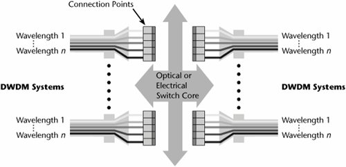
Optical Switches
Optical switches, sometimes referred to as optical cross-connects or wavelength routers, are devices that reside at junction points in optical backbones and enable carriers to string together wavelengths to provide end-to-end connections (see Figure 11.6). They link any of several incoming lines to any of several outgoing lines and automatically reroute traffic when a network path fails. An optical switch is the optical version of a general-purpose switch that provides flexibility and reliability in today's PSTN. Optical switches move transmissions between fiber segments and also enable some network management activities, including optical-layer restoration and reconfiguration, dynamic wavelength management, and automated optical-layer provisioning.
Figure 11.6. An example of an optical switch
There are three key issues in selecting optical switches:
- Number of ports Carriers are looking for devices that can scale to more than 1,000 ports.
- Automation Carriers want to provision strings of wavelengths from a remote console in real-time.
- Granularity Carriers want a switch to handle small as well as large bandwidths so that they can eliminate multiplexers.
Optical switches fall into two main categories. First, the multiservice provisioning platform (MSPP) enables carriers to get a quick start on offering a full range of services. It resides either in the carrier's point of presence (POP) or at the customer site, and it incorporates DWDM and offers customers different grades of IP service, telephony, and other offerings. (MSPPs are discussed in detail later in this chapter.) Second, big switches can be deployed at the carrier's local exchange. These switches act as on-ramps, funneling large volumes of traffic from IP, ATM, and MPLS backbones on and off the optical core.
Challenges in Deploying Optical Switches
Because we are in the early stages with optical switches, we have to deal with issues such as how to quickly provision services, how to accommodate billing, and how to elegantly separate services. In the next three to five years, we should start seeing these more sophisticated elements become available in pure optical form.
As mentioned earlier, with end-to-end optical networking, because transmission rates are reaching the Tbps, Pbps, and even the Ebps levels, the bottleneck is moving to the network elements. The faster the light pulses are emittedthat is, the faster the data rates on the line getthe more technically challenging it is to handle optical-electrical-optical conversions at line speed. Therefore, to fully take advantage of the capacity being created by WDM, fiber networks need switches capable of rerouting light. The good news is that the cost of optical components has decreased by 40% in recent years, and it is expected to continue to drop by 40% to 60% per year.
The biggest problem that converged telcos are now facing is how to accurately forecast their future bandwidth requirements. Transmission speeds are doubling every 12 months, so it is essential that we have infrastructures capable of providing a large amount of bandwidth on short notice and at reasonable cost. Without intelligent optical networking, adding an OC-48 circuit over existing dark fiber can take between 6 and 9 months. To automate provisioning, we need to also address how we can look into a wavelength to determine how to properly act on it.
Optical switches enable improved reliability, improved scalability, and flexible service provisioning. They also reduce the capital required to add additional capacity, and the overall savings can then be passed on to the customer. Deploying optical networking technology in the metro area can bring the benefits of converged networks down to the customer's premises. The end-to-end optical infrastructure can then support advanced services such as true bandwidth-on-demand.
Optical Switching Fabrics
Optical switches are components in a fiber-optic network that direct light beams from one fiber to another, and they are used as an alternative to hubs for routing connections. Optical switching fabrics, such as the following, can provide subsystems that connect one wavelength to another:
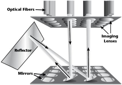
- Microelectromechanical system (MEMS) switches A MEMS switch uses an array of microscopic mirrors to reflect light from an input port to an output port.
- Bubble switches Similar to inkjet printers, bubble switches use heat to create small bubbles in fluid channels that then reflect and direct light.
- Thermo-optical switches With thermo-optical switches, light passing through glass is heated up or cooled down by using electrical coils. The heat alters the refractive index of the glass, bending the light so that it enters one fiber or another.
- Liquid crystal display (LCD) switches LCDs use liquid to bend light.
- Tunable lasers Tunable lasers pump out light at different wavelengths, and they can switch from one wavelength to another very quickly.
MEMS-based optical switches were among the first technology to be deployed (see Figure 11.7), with several companies offering a new generation of optical high-capacity switches. Unfortunately, the market for optical switches in general has been fraught with difficulties, with service providers yet to make big, bold commitments to adopt the technology. However, developments and announcements are continuing. For example, in early 2006, Lambda OpticalSystems (www.lambdaopticalsystems.com) unveiled its LambdaNode 2000, an all-optical switch that scales as large as 256 x 256 ports in one bay and is the first all-optical switch to combine switching and transport functions in one system.
Figure 11.7. A MEMS switch
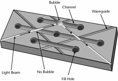
Another approach in optical switches, bubble switches, involves using inkjet printer technology to switch packets in optical switches. In inkjet printers, tiny enclosures are filled with gas, and they sit behind the ink in a printer. In front of each enclosure is a minute nozzle. When a character is called for, the gas behind the nozzles that form the letters is heated, and the ink is shot onto the paper (see Figure 11.8). Bubble switches work in a similar manner but use liquid as well as gas. If a packet is supposed to stay on the same network, the liquid remains cool, and the packet passes through unscathed. If a switch is required, the liquid is heated and turns to gas. If the gas has the correct reflective properties and if the cavity is precisely positioned, the light is bounced in the right direction.
Figure 11.8. A bubble switch
Yet another optical switching approach involves thermo-optic switches. Light is passed through glass that is then heated up or cooled down with electrical coils. The heat alters the refractive index of the glass, bending the light so that it enters one fiber or another (see Figure 11.9).
Figure 11.9. A thermo-optic switch
An LCD switch, as shown in Figure 11.10, uses liquid to bend light.
Figure 11.10. An LCD switch
There are many issues to address with these evolving types of optical switches. Again, because we are in the early days of these technologies, we have not yet tested each of them under a full network load. We still have to address how well these technologies will scale. Carriers are looking for modular switches that can scale to thousands of ports. Switching speed is another consideration; routing traffic packet by packet will require switching speeds measured in nanoseconds.
Integrated Photonic Circuits
Vendors are developing ways to make the optical equivalent of integrated circuits. The goal is to consolidate large numbers of separate optical devices into a single chip, customizing them for different applications and drastically reducing costs while improving performance. One of the key issues involved is the selection of materials. A wide variety of materials are being used for different applications, including silica, silicon, polymer, and rare earths. Each material has unique advantages and disadvantages in terms of the performance of the chip and the ease and cost of manufacturing it. In these early days for this technology, vendors are producing relatively simple components, such as DWDM chips, small switch modules, and passive splitters.
Indium phosphide (InP) is the material of choice for optoelectronic integration. It is likely to revolutionize the communications industry, much as silicon revolutionized the computer industry. InP is a compound made of binary crystals produced by combining one element from the metallic Group III of the periodic table with an element from the nonmetallic Group V. InP has photonic properties that allow for the large-scale integration of components such as lasers, detectors, dynamic components, passive waveguides, and electronics onto the same chip. Its qualities make InP a good fit for circuits in wireless devices as well. Components built with InP consume very little power, permitting them to remain connected to the Internet over high-speed wireless networks for extended periods. InP's shortcomings include low yields of InP wafers in manufacturing (less than 40%) and the labor-intensive effort to build optical networking equipment, which make these components expensive.
Integrated optical circuits could lower costs of components by 90%. Currently, components account for as much as 50% of the cost on a long-haul US$100,000 DWDM device and 15% of the cost on a US$40,000 metro WDM system. Innovations in optical chip making will make possible 100Mbps network connections for homes at less than $10 per month.
Optical Network Management
One of the most important areas of any networking technology is network management, which in the case of optical networks involves network restoration, wavelength services, and performance.
As discussed earlier in this chapter, most optical networks today are based on an existing SDH/SONET architecture. One of the great strengths of SDH/SONET is, in fact, its network restoration capabilities. However, as new elements such as WDM systems are added, it can be difficult to ensure that restoration techniques are not in conflict. At the very least, the network management system must enable the service provider to identify any possible conflicts (not to mention resolve them). Along with managing the overall network, the network management system performs some specific tasks, such as monitoring the signal performance for each wavelength. And the more elements there areincluding WDM/DWDM/CWDM, OADMs, ROADMs, optical cross-connects, and optical switchesthe more difficult the job. Also, as the number of wavelengths grows, there has to be a facility to monitor and manage each one of them. Of course, the ability to provision services quickly is also a key requirement, and a proper network management system can help providers not only manage their own networks efficiently but also offer end-to-end managed wavelength service.
The Optical Edge |
Part I: Communications Fundamentals
Telecommunications Technology Fundamentals
- Telecommunications Technology Fundamentals
- Transmission Lines
- Types of Network Connections
- The Electromagnetic Spectrum and Bandwidth
- Analog and Digital Transmission
- Multiplexing
- Political and Regulatory Forces in Telecommunications
Traditional Transmission Media
Establishing Communications Channels
- Establishing Communications Channels
- Establishing Connections: Networking Modes and Switching Modes
- The PSTN Versus the Internet
The PSTN
- The PSTN
- The PSTN Infrastructure
- The Transport Network Infrastructure
- Signaling Systems
- Intelligent Networks
- SS7 and Next-Generation Networks
Part II: Data Networking and the Internet
Data Communications Basics
- Data Communications Basics
- The Evolution of Data Communications
- Data Flow
- The OSI Reference Model and the TCP/IP Reference Model
Local Area Networking
Wide Area Networking
The Internet and IP Infrastructures
- The Internet and IP Infrastructures
- Internet Basics
- Internet Addressing and Address Resolution
- The Organization of the Internet
- IP QoS
- Whats Next on the Internet
Part III: The New Generation of Networks
IP Services
Next-Generation Networks
- Next-Generation Networks
- The Broadband Evolution
- Multimedia Networking Requirements
- The Broadband Infrastructure
- Next-Generation Networks and Convergence
- The Next-Generation Network Infrastructure
Optical Networking
- Optical Networking
- Optical Networking Today and Tomorrow
- End-to-End Optical Networking
- The Optical Edge
- The Optical Core: Overlay Versus Peer-to-Peer Networking Models
- The IP+Optical Control Plane
- The Migration to Optical Networking
Broadband Access Alternatives
- Broadband Access Alternatives
- Drivers of Broadband Access
- DSL Technology
- Cable TV Networks
- Fiber Solutions
- Wireless Broadband
- Broadband PLT
- HANs
Part IV: Wireless Communications
Wireless Communications Basics
- Wireless Communications Basics
- A Brief History of Wireless Telecommunications
- Wireless Communications Regulations Issues
- Wireless Impairments
- Antennas
- Wireless Bandwidth
- Wireless Signal Modulation
- Spectrum Utilization
Wireless WANs
- Wireless WANs
- 1G: Analog Transmission
- 2G: Digital Cellular Radio
- 5G: Enhanced Data Services
- 3G: Moving Toward Broadband Wireless
- Beyond 3G
- 4G: Wireless Broadband
- 5G: Intelligent Technologies
WMANs, WLANs, and WPANs
Emerging Wireless Applications
- Emerging Wireless Applications
- The Handset Revolution
- Mobile IP
- The IP Multimedia Subsystem
- Mobile Gaming
- Mobile Video
- Mobile TV
- Mobile Content
Glossary
EAN: 2147483647
Pages: 160
