Spectrum Utilization
The wireless spectrum is limited. Wireless is like having one invisible cable in the sky that the whole world has to share. This is one of the major limitations of wireless, and we need techniques for efficiently using the spectrum that we do have. There are several steps in reusing spectrum.
The first step in spectrum reuse is to apply space divisionthat is, carve up the service area into smaller coverage areas. The key purpose of space division is to reuse frequencies across the coverage areas, or cells. The second step is to apply a multiple-access technique to allow the sharing of spectrum by multiple users. After you have delineated the space and combined multiple conversations onto one channel, you can apply spread spectrum, duplexing, and compression techniques to use the bandwidth even more efficiently. The following sections discuss these steps in more detail.
Using the Available Radio Spectrum
The first key characteristic of a radio transmission system is how it makes use of the available radio spectrum, or bandwidth. As discussed in the following sections, four major techniques are used to allocate capacity: Space Division Multiplexing, Frequency Division Multiple Access (FDMA), Time Division Multiple Access (TDMA), and spread spectrum (implemented as Code Division Multiple Access [CDMA] in 2G networks and as either W-CDMA or OFDM in 3G cellular networks).
Space Division Multiplexing
The cellular concept involves subdividing coverage areas. Mobile telephony is not a new invention. It has been around since the early 1950s, but at that time, two things limited its availability to the mass market. First, we were using very high-powered antennas. So, when we relayed a signal, it would have strength over a coverage area of perhaps 100 miles (161 km) in diameter. Second, at that time, the spectrum management agencies issued very few frequencies (perhaps one or two dozen) that could be used for purposes of mobile communications. In the relatively large coverage area of 100 miles (161 km) or so, only 12 to 24 channels were available. The majority of these few channels were reserved for critical services, such as police and other emergency services, as well as for those who could afford a body builder to carry those big phones that operated at low frequencies over long stretches.
In the 1970s, two things changed. The first was the advent of the low-power transmitter receiver tower, which reduced the coverage area to a cell size that was only about 8 miles (13 km) in diameter. Second, the regulatory agencies made available large amounts of spectrum for use in support of mobile communications, and depending on the location, anywhere from 600 to 1,000 channels were made available to service providers.
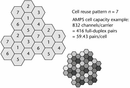
The cellular architecture depends on cells organized into a reuse pattern. In the traditional analog cellular network, the cellular reuse pattern is n = 7 and is often depicted as a honeycomb configuration of what are called seven cells (see Figure 13.3). The idea of spectrum reuse is that you can reuse frequencies as long as they are not in adjacent cells. Say that in the honeycomb configuration, 700 channels are available. Each of the cells could make use of 100 of those channels. The next honeycomb configuration could then reuse those 100 channels, as long as those channels were not adjacent to one another between cells.
Figure 13.3. Space division for spectrum reuse
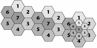
As the density of subscribers increases, the next step is to subdivide the cells into smaller coverage areas, based on accepted reuse patterns. The traditional analog cellular network uses macrocells (see Figure 13.4). This network was for fast-moving users, traveling distances of miles on their end-to-end journey. The coverage area was about 8 miles (13 km) in diameter, and the base station power was rather greatgenerally 10 watts or more. This network offered low deployment costs and a small number of handoffs. Depending on how many channels the spectrum agency gave the region, a cell could support up to about 60 users.
Figure 13.4. Analog cellular reuse pattern
As the demand for use increased, we started to migrate toward a microcell architecture. Users of this architecture were assumed to be moving more slowly than those in a macrocell approach; they were, for example, people trapped in a traffic grid, people on golf carts on a golf course, people riding bicycles in a city, or pedestrians anywhere. These users traveled distances of less than 1 mile (1.5 km) end to end. Therefore, there are not as many handoffs involved with microcells as there are with macrocells.
With macrocells and high-speed vehicles, in 1980, when processing power was significantly lower than it is today, if you were moving very rapidly through cell boundaries, there would be undue strain on the processing power of the systems, and calls might be dropped. But by the time microcells started to come about, handoffs were facilitated by more rapid processing. The coverage area of a microcell is about 0.6 miles (1 km) in diameter. Compared to macrocells, this architecture offers better frequency reuse, lower power, and better battery life, as well as smaller subscriber units.
It is not always useful to define a cell with a full coverage of 360 degrees. In some cases, cells with a particular shape and coverage are needed. These cells are called selective cells. A typical example of selective cells is the cells that may be located at the entrances of tunnels, where 360-degree coverage is not needed. In this case, a selective cell with a coverage of 120 degrees is used.
The demand for spectrum is growing beyond what even the microcell design can provide, and further shrinkage of the cell size is mandated, so we are now employing the picocellthat is, the tiny cellarchitecture. This approach is for stationary or very slow-moving usersfolks who dash out of a seminar during a conference and stand by a window so they can conduct a conversation, or coffee lovers who check e-mail over lattes. These users are not traveling great distances, maybe 330 to 1,000 feet (100 to 300 m) end to end. The coverage radius of a picocell is only about 150 feet (46 m), and because it's such a small coverage area, the base station power is also very small10 milliwatts or less. Therefore, compared to the microcell design, the picocell design offers even better frequency reuse, even lower power, even smaller subscriber units, and even better, longer battery life. The picocell architecture does create some concerns in the engineering realm; for example, Tokyo needed to plan how to implement more than 40,000 cells for its Personal Handyphone System (PHS) deployment. There are tradeoffs with the various designs: You can serve greater densities with the picocell design than with other designs, but at the cost of a bigger engineering project.
The concept of umbrella cells was introduced to address the situation where a large number of handoffs occurs among many small neighboring cells. An umbrella cell covers several microcells or picocells. The power level inside an umbrella cell is increased compared to the power levels used in the microcells that form the umbrella cell. When the speed of the mobile device is too high, the mobile device is handed off to the umbrella cell. The mobile device then stays longer in the same cell (in this case, the umbrella cell), reducing the number of handoffs and the work of the network.
FDMA
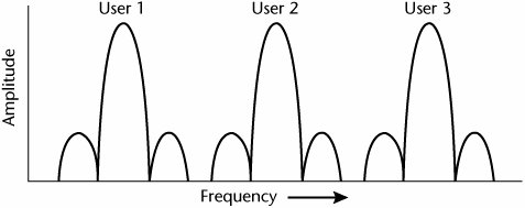
With FDMA, which is used in analog cellular systems, each user is assigned to a different frequency; everybody is speaking at the same time, but each conversation is on a different portion of the frequency band. FDMA is characterized as facilitating what would today be called low capacityapproximately 60 users per cell. Given the number of users today, let alone what tomorrow will bring, FDMA alone can no longer handle the volume.
The cost of FDMA handsets is low, as these are not smart devices. For example, an FDMA-based device does not know how to search for another frequency that has a better transmission quality associated with it. This approach is inexpensive for the user, but the service operator needs to have a transceiver for each channel, which means the base station cost is high. And because it's an analog technology, FDMA also consumes a great deal of power, and the cost associated with the power consumption is greater than with digital systems.
The advantage of FDMA is that it doesn't need strict clocking devices to enable synchronization between the base stations, as would, for example, TDMA. As Figure 13.5 shows, everybody uses the system at the same time, but each user is working off a different frequency.
Figure 13.5. FDMA
Although analog FDMA systems are no longer common, with most analog systems having been decommissioned at this point, the FDM technique is still very important because it is required to divide the allocated spectrum into individual channels to which other techniques are then applied to enable multiple users to use a channel simultaneously.
TDMA
TDMA, which is used in 2G digital cellular systems, WLANs, and Personal Communications Services (PCS) systems, is actually a combination of FDM and TDM. In TDMA systems, you first divide the available or allocated frequency spectrum into a number of channels by using FDM. Then, within each channel, you apply TDM to carry multiple users, interleaved in time. Therefore, one transceiver can support multiple channels. Various cellular network standards are based on TDMA, including Global System for Mobile Communications (GSM), Universal Wireless Communications (UWC), and Personal Digital Cellular (PDC). UWC-136 TDMA technology, also referred to as ANSI-136, provides a three-to-one gain in capacity compared to analog technology. Each caller is assigned a specific time slot for transmission. GSM supports eight users per channel, resulting in an eightfold increase in capacity. (These standards are discussed in further detail in Chapter 14.)
The digital handsets associated with TDMA are more intelligent than those used with FDMA. For example, they have scanning capabilities, and if the channel you are on is encountering anomalies that are lending themselves to transmission errors, the handset can search for an available channel that provides better performance.
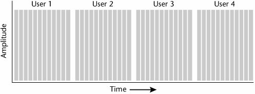
The key benefits of TDMA are that it offers greater capacity and spectral efficiency than FDMA. As Figure 13.6 shows, in TDMA, everybody is talking on the same frequencies but at different moments in time. The users perceive their conversations as being continuous, even though each is actually getting very rapid samples of his or her conversation.
Figure 13.6. TDMA
Spread Spectrum
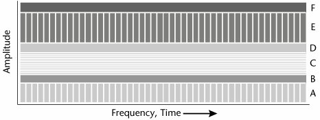
Spread spectrum is a multiple-access technique that is receiving a great deal of attention today. In spread spectrum, everybody is using the same frequency at the same time. This is referred to as universal frequency reuse. Spread spectrum provides the ultimate in terms of the supported density of users, and it is possible because each conversation is uniquely encoded. In spread spectrum, a single spectrum of bandwidth is available for all the users. As Figure 13.7 shows, in spread spectrum, although everybody is using the same frequencies at the same time, each conversation is uniquely encoded, allowing the transceiver to pick it out from among all the conversations.
Figure 13.7. Spread spectrum
Spread spectrum has become a critical technology. It is used in 3G cellular systems as well as WLANs, and it is the basis of the majority of emerging wireless broadband solutions. There are two major benefits to spread spectrum: greater resistance to interference (and hence greater reliability) and greatly improved capacity.
There are two generations of spread spectrum. The first generation, CDMA, operates in an allocation of 1.25MHz. The second generation of CDMA, called Wideband CDMA (W-CDMA), operates over allocations of either 5MHz, 10MHz, or 15MHz. As is implied by the name, W-CDMA can support higher data rates than can CDMA. Both generations of CDMA use a unique code for each conversation, and both use spread spectrum techniques. One advantage of W-CDMA is that it uses a bigger channel than CDMA, which means that it can carry more calls and that those calls can be encoded in longer strings. The longer strings, in turn, mean greater security and better performance.
Spread spectrum is characterized by not requiring any timing coordination, so clocking is not necessary. It offers great reliability because it is highly resistant to interference. Spread spectrum has greatly improved capacity over FDMA and TDMA; the spectral efficiency of spread spectrum, as standardized in IS-95, is 10 to 20 times greater than that of an analog cellular network. The number of users who can be serviced depends on the location of the usershow many of them are within a given cell and what signal-to-noise ratio the service provider deems acceptable. Spread spectrum allows for two compression ratios for digitized voice, and they vary according to the channel quality: 13Kbps, which is used to provide near-land-line voice qualities (e.g., in support of something like wireless local loop), and 8Kbps, which is used to maximize the use of the spectrum and extend battery life. It is important to realize that spread spectrum requires complex power control schemes, and power control is very important in spread spectrum.
On spread spectrum networks, channels can be reused in adjacent cells without creating co-channel interference because different pseudorandom number (PN) codes are used in each cell site. Spread spectrum was developed by the military to be secure. The wide spreading of the signal makes if difficult to detect and jam.
As discussed in the following sections, there are three basic types of spread spectrum techniques: Frequency Hopping Spread Spectrum (FHSS), Direct Sequence Spread Spectrum (DSSS), and Orthogonal Frequency Division Multiplexing (OFDM).
FHSS
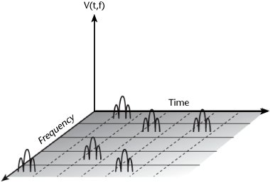
With FHSS, which is the oldest of the spread spectrum techniques, the frequency hopping varies in a known pattern, and separate error correction must be included. The concept involves a system that hops between frequencies in a random pattern, known only to the transmitter and receiver (see Figure 13.8). The transmitter sends on a channel for only a short period of time and then hops to a different channel. Slow frequency hopping is used to combat fading.
Figure 13.8. FHSS
Along with providing resistance to jamming, an FHSS system also addresses the problem of frequency-selective fading. Because the transmitter does not stay on any one frequency for a long period of time, fading at a particular part of the frequency spectrum is minimized. The disadvantage of FHSS is that the more hopping channels needed, the greater the bandwidth required, although a set of hopping channels can be shared by a number of users.
FHSS is used by the original Bluetooth standard (IEEE 802.15.1) for PANs, which is discussed in detail in Chapter 15.
DSSS
DSSS is used in most contemporary systems, including 3G cellular networks, CDMA-based networks, and 802.11b WLANs. DSSS requires greater bandwidth than does FHSS, but that is exactly what makes its performance so good.
With DSSS, each transmitted bit is first converted into a series of narrower pulses, referred to as chips. DSSS multiplies the data bits by a very fast pseudorandom bit pattern (PN code) that spreads the data into a large coded stream that takes the full bandwidth of the channel. The chips are then transmitted through a digital modulator.
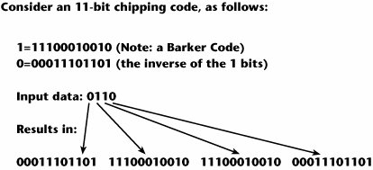
The bandwidth expansion factor refers to the number of bits in the spreading code. There are many types of spreading codes in use; for example, Barker Code is used in 802.11, Complementary Code Keying (CCK) is used in 802.11b, and 64-bit Walsh Code is used in CDMA cellular. Figure 13.9 shows an example of DSSS that uses Barker Code, which is an 11-bit chipping code. The 1 bits are encoded as a particular sequence of 1s and 0s, and the 0 bits are the inverse of that sequence. In the course of a transmission, if a bit is affected by noise and several chips get knocked out, the receiver can determine from the pattern of remaining bits whether a 1 or a 0 got knocked out and recover that information accurately. This is why DSSS provides such good performance and resistance to interference and noise. DSSS also provides great reliability because the DSSS operation generates more bits per second than it starts with, and the resulting signals spread over a wide range of frequencies when it is transmitted, minimizing the impact of interference and multipath fading.
Figure 13.9. An example of DSSS
OFDM
OFDM is the newest spread spectrum technique, and its main purpose is to resolve the problems that result from multipath distortion. OFDM has some key advantages over CDMA, which is used in many of today's 3G cellular networks. First, it is more robust, which means it provides better performance in multipath situations. It also allows for simpler receivers. Perhaps most importantly, OFDM is more amenable to MIMO technologies than are the other spread spectrum techniques. A Nortel (www.nortel.com) trial conducted in early 2005 provides a good example: Nortel was able to demonstrate peak data rates of 37Mbps over a standard 5MHz PCS mobility band. Using OFDM and MIMO, wireless subscribers could download a 128MB file in approximately 30 seconds, 4 to 10 times faster than today's 3G networks can support (see www.nortel.com/corporate/news/newsreleases/2005a/03_09_05_mimo_ofdm.html). In another Nortel trial (see http://telephonyonline.com/wireless/technology/mimo_ofdm_091905/), using OFDM and MIMO enabled a mobile user to download a 264MB file at 37Mbps while simultaneously viewing two live streaming videos, over a standard 5MHz PCS band. The download took less than 1 minute in this trial; it would take 90 minutes with today's networks.
OFDM and MIMO are critical technologies associated with most of the advanced and emerging wireless systems, including Beyond 3G (B3G) or 3.5G and 4G. Many areas of wireless solutions employ OFDM. One is mobile wireless, which includes the IEEE 802.16e, IEEE 802.20, and Flash-OFDM standards. Another is fixed wireless broadband, encompassing IEEE 802.16a/Revision D, WLANs such as IEEE 802.11a and 802.11g, and the European HiperLan2. OFDM is also used in Ultra-Wideband (UWB) PANs. DTV and HDTV using the Digital Video Broadcasting-Terrestrial (DVB-T) and Digital Audio Broadcasting (DAB) standards also rely on OFDM. Military high-frequency modems also make use of OFDM. OFDM is also used in a variety of wired broadband alternatives, including ADSL (where it is known as Discrete Multitone [DMT]), cable modems, and powerline telecommunications (PLT).
OFDM is a combination of two key principles:
- Multicarrier transmission Multicarrier transmission is a technique that divides the available spectrum into many subcarriers, with the transmission rate reduced on each subcarrier. OFDM is similar to FDM in that multiple-user access is achieved by subdividing the available bandwidth into multiple channels that are then allocated to users. However, OFDM uses the spectrum much more efficiently than FDM by spacing the channels much more closely together. This is achieved by making all the carriers orthogonal (i.e., at right angles to or independent of) to one another, preventing interference between the closely spaced carriers. Making the carriers for each channel orthogonal to one another allows them to be spaced very closely. For a good graphic representation of OFDM, see Telephony Online's article "Building Future Networks with MIMO and OFDM" at http://telephonyonline.com/wireless/technology/mimo_ofdm_091905/.
- Adaptive modulation An adaptive modulation system supports a variety of modulation schemes. The quality of the radio path determines which modulation technique is most appropriate. Techniques supported include 16-QAM, 64-QAM, QPSK, and DPSK.
OFDM overcomes most of the problems with both FDMA and TDMA, including nonefficient use of spectrum and the requirement for clocking or synchronization with TDMA. OFDM splits the available bandwidth into many narrowband channels (typically 100 to 8,000), referred to as subcarriers.
OFDM offers improved resistance to noise and interference at particular frequencies as well as immunity to frequency-selective fading. Information can be reconstructed without receiving the entire transmission band. OFDM is almost always used in conjunction with channel coding or an error correction technique. One approach is referred to as Coded Orthogonal Frequency Division Multiplexing (COFDM). COFDM is widely used in Europe and other places where the DAB standard has been adopted for digital radio broadcasting and for terrestrial digital TV, as in the DVB-T standard. COFDM is also used in ADSL transmission. The major benefit of COFDM is that it makes broadcasts relatively immune to multipath distortion and signal fading due to atmospheric conditions or passing aircraft. It is a complex technique, but by combining OFDM with error-correcting codes, adaptive equalization, and reconfigurable modulation, COFDM provides many beneficial properties, including resistance to multipath, phase distortion, fading, and burst noise.
OFDM also offers improved bandwidth efficiency because it can support more users on the same transmission channel by using different spreading codes. OFDM makes it easy to filter out noise: If a particular range of frequencies suffers from interference, the carriers within that range can be disabled or made to run more slowly. Another feature of OFDM is that the speeds of the upstream and downstream channels can be varied by allocating either more or fewer carriers for each purpose. Some forms of Rate-Adaptive DSL (RADSL) use this feature in real-time so that bandwidth is allocated to whichever stream needs it most.
Orthogonal Frequency Division Multiple Access (OFDMA) is a proprietary enhancement to OFDM technology, introduced by Runcom Technologies (www.runcom.com) in 2000. Whereas OFDM involves 256 subcarriers, OFDMA defines either 2,048 or 4,096 subcarriers. In current OFDM systems, only a single user can transmit on all the subcarriers at any given time, and TDMA or FDMA is used to support multiple users. OFDMA, on the other hand, allows multiple users to transmit simultaneously on the different subcarriers per OFDM symbol. The end result is improved spectral efficiency. Because OFDMA enables more efficient duplexing techniques, including FDD and TDD, the created signal is immune to interference and is therefore capable of high data throughput. In addition, OFDMA improves the power gain per channel, providing better coverage and range availability, larger cell radius, and smaller power amplifiers and antennas, ultimately leading to lower investment in capital equipment.
OFDMA, also referred to as Multiuser-OFDM, is being considered as a modulation and multiple-access method for upcoming fourth-generation (4G) wireless networks, and it is being embraced by a number of current technologies, including DVB and WiMax. It is also a preferred technology driving the BWA market.
Duplexing Techniques
Another way in which the operations of wireless networks differ, and hence also the standards differ, is the duplexing techniquethe procedure for separating the incoming and outgoing conversations. Duplex transmission refers to the ability to send information in both directions over a single channel. Two transmitters cannot use the same channel at the same time because they will interfere with one another, but there are two techniques for enabling full-duplex transmission: Frequency Division Duplex (FDD) and Time Division Duplex (TDD).
FDD
With FDD, two separate channels are assigned for transmission: the transmit channel and the receive channel. FDD requires more bandwidth than TDD. FDD is the legacy technique used for point-to-point links supporting voice, which is symmetric and defined by predictable traffic. Hence, FDD is the most widely used technique in cellular networks. Because there is much equipment based on legacy FDD point-to-point radio links, FDD is a top priority for some manufacturers.
TDD
In TDD, which is found in various standards across all the technology domains, including WWANs, WMANs, WLANs, and WPANs, the two ends take turns sending on the same channel. TDD can be designed as a contention system, where an access protocol (such as CSMA/CA) minimizes the chance of collision. TDD can also be designed for no contention, where time slots are defined, and each direction uses assigned time slots; this is referred to as a "ping-pong" technique. TDD makes practical the reallocation of spectral resources from uplink to downlink or vice versa. The ability to adapt the spectrum resources to the actual traffic pattern significantly improves frequency resource utilization. These characteristics make TDD an attractive alternative in support of triple play (i.e., a single carrier's offering of voice, data, and TV services).
TDD does have some drawbacks, including a requirement for burst demodulators and more difficult synchronization of uplink transmission due to the absence of frequency and clock references. However, due to its superior performance in supporting spectrum efficiency and flexibility, TDD is the preferred solution in broadband fixed wireless access (BFWA) networks. (BFWA systems are discussed in Chapter 15.)
Compression Techniques
After carving space into cells and applying multiple-access techniques within each cell to make better use of the bandwidth available, it is possible to apply compression to make greater use of the bandwidth within each given channel. Compression is very important because it improves the use of a precious resource: the communications channel.
Voice compression techniques use voice coders/decoders (vocoders), of which there are two general types:
- High-bit-rate vocoders These vocoders are used by PCS, wireless local loops, and wireless office telecommunication systems applications. These vocoders carry voice by using 32Kbps Adaptive Differential Pulse Code Modulation (ADPCM). A bit rate this high emulates the quality achieved on the PSTN, and no additional error detection and correction is necessary.
- Low-bit-rate vocoders These vocoders are used in cellular systems that deal with vehicular traffic, where large cells need to facilitate a large number of conversations, or anywhere bandwidth efficiency is critical, such as densely populated areas. These vocoders reduce the voice down to 8Kbps, using extensive channel coding techniques that help facilitate error correction, such as linear predictive coding (LPC), Quantized Code-Excited Linear Prediction (QCELP), or Vector Sum Excited Linear Prediction (VSLEP). GSM uses Regular Pulse Excitation Long Term Prediction (RPE LTP), which carries digitized voice at 13Kbps, achieving good voice quality (albeit not comparable to that achieved on good old-fashioned landlines).
Unfortunately, in the realm of data, there are no set standards for data compression; many techniques exist, and overall, data compression is underused.
Part I: Communications Fundamentals
Telecommunications Technology Fundamentals
- Telecommunications Technology Fundamentals
- Transmission Lines
- Types of Network Connections
- The Electromagnetic Spectrum and Bandwidth
- Analog and Digital Transmission
- Multiplexing
- Political and Regulatory Forces in Telecommunications
Traditional Transmission Media
Establishing Communications Channels
- Establishing Communications Channels
- Establishing Connections: Networking Modes and Switching Modes
- The PSTN Versus the Internet
The PSTN
- The PSTN
- The PSTN Infrastructure
- The Transport Network Infrastructure
- Signaling Systems
- Intelligent Networks
- SS7 and Next-Generation Networks
Part II: Data Networking and the Internet
Data Communications Basics
- Data Communications Basics
- The Evolution of Data Communications
- Data Flow
- The OSI Reference Model and the TCP/IP Reference Model
Local Area Networking
Wide Area Networking
The Internet and IP Infrastructures
- The Internet and IP Infrastructures
- Internet Basics
- Internet Addressing and Address Resolution
- The Organization of the Internet
- IP QoS
- Whats Next on the Internet
Part III: The New Generation of Networks
IP Services
Next-Generation Networks
- Next-Generation Networks
- The Broadband Evolution
- Multimedia Networking Requirements
- The Broadband Infrastructure
- Next-Generation Networks and Convergence
- The Next-Generation Network Infrastructure
Optical Networking
- Optical Networking
- Optical Networking Today and Tomorrow
- End-to-End Optical Networking
- The Optical Edge
- The Optical Core: Overlay Versus Peer-to-Peer Networking Models
- The IP+Optical Control Plane
- The Migration to Optical Networking
Broadband Access Alternatives
- Broadband Access Alternatives
- Drivers of Broadband Access
- DSL Technology
- Cable TV Networks
- Fiber Solutions
- Wireless Broadband
- Broadband PLT
- HANs
Part IV: Wireless Communications
Wireless Communications Basics
- Wireless Communications Basics
- A Brief History of Wireless Telecommunications
- Wireless Communications Regulations Issues
- Wireless Impairments
- Antennas
- Wireless Bandwidth
- Wireless Signal Modulation
- Spectrum Utilization
Wireless WANs
- Wireless WANs
- 1G: Analog Transmission
- 2G: Digital Cellular Radio
- 5G: Enhanced Data Services
- 3G: Moving Toward Broadband Wireless
- Beyond 3G
- 4G: Wireless Broadband
- 5G: Intelligent Technologies
WMANs, WLANs, and WPANs
Emerging Wireless Applications
- Emerging Wireless Applications
- The Handset Revolution
- Mobile IP
- The IP Multimedia Subsystem
- Mobile Gaming
- Mobile Video
- Mobile TV
- Mobile Content
Glossary
EAN: 2147483647
Pages: 160
